University
of
Southern
Queensland
Faculty
of
Engineering
and
Surveying
Design
and
Develop
Virtual
Reality
Games
Utilising
the
“Anti
‐
gravity"
Arm
Support
for
Stroke
Rehabilitation
Therapy
A dissertation submitted by
Ryan
Fitzhenry
In fulfilment of the requirements of
Courses
ENG4111
and
4112
Research
project
Towards the degree of
Bachelor
of
Engineering
(Computer
Systems)
Submitted:
October,
2009
Abstract
Approximately 16,000 Australians each year are left with a disability as a direct consequence
of stroke. The number of strokes that occur in Australia each year is increasing, putting a
strong reliance on home and community based rehabilitation having an increasing role in
the rehabilitation process.
Strokes are caused by a sudden disruption to the flow of blood to parts of the brain. If an
artery is blocked, the brain cells (neurons) cannot make enough energy and will eventually
stop working.
Stroke affects patients in a number of different ways depending on the severity of the
stroke and the type of stroke in which the patient suffers from. There two main types of
disabilities that are a result of stroke: hemiplegia and hemiparesis.
The project aims to develop a virtual reality application to assist in the rehabilitation of the
upper extremities of stoke patients who suffer from hemiparesis. The project will endeavour
to design a low cost, home based system that will motivate patients by creating
intermediate goals that can be adopted into the rehabilitation process. The project will
utilise the "anti‐gravity" arm support system to lessen the affect of reduced muscle strength
and control. The project objectives are to:
Research relevant background information on the effects of stroke.
Research traditional methods of stroke rehabilitation and assessment of
rehabilitation progression.
Implement hardware and program for position data acquisition.
Develop virtual reality application for exercise and rehabilitation assessment.
The project is based around detecting the movement or the patients arm and creating a
computer representation. This has been performed by monitoring the potentiometers on
the “anti‐gravity” arm support utilizing the PIC AXE microcontroller. The microcontroller to
converts the signal into a digital integer and transfers them to the computer via a serial link.
The games were designed around conventional physiotherapy exercises allowing the user to
complete the exercises in a self motivating environment. The games were developed in both
2D and 3D environments utilizing Microsoft’s XNA games studio.
The project has been successful in accurately representing a user’s movement within a
virtual environment. This has been tested by use of advance 3D mapping techniques;
University of Southern Queensland
Faculty of Engineering and Surveying
ENG4111 Research Project Part 1 &
ENG4112 Research Project Part 2
Limitations of Use
The Council of the University of Southern Queensland, its Faculty of Engineering and Surveying, and the staff of the University of Southern Queensland, do not accept any responsibility for the truth, accuracy or completeness of material contained within or associated with this dissertation.
Persons using all or any part of this material do so at their own risk, and not at the risk of the Council of the University of Southern Queensland, its Faculty of Engineering and Surveying or the staff of the University of Southern Queensland.
This dissertation reports an educational exercise and has no purpose or validity beyond this exercise. The sole purpose of the course "Project and Dissertation" is to contribute to the overall education within the student’s chosen degree programme. This document, the associated hardware, software, drawings, and other material set out in the associated appendices should not be used for any other purpose: if they are so used, it is entirely at the risk of the user.
Professor Frank Bullen
Dean
Certification
I certify that the ideas, designs and experimental work, results, analyses and conclusions set out in this dissertation are entirely my own effort, except where otherwise indicated and acknowledged.
I further certify that the work is original and has not been previously submitted for assessment in any other course or institution, except where specifically stated.
Ryan Fitzhenry
0050025782
____________________________
Signature
____________________________
Date
Acknowledgements
I would like to thank the following people:
My supervisor Selvan Pather for all the time, effort and enthusiasm which he has generously
donated to the project.
My family for all their love and support they have provided over the last year.
My girlfriend Ally for her all support and putting up with me talking continuously about the
project.
Contents
Introduction ... 1
1.1 Introduction ... 1
1.2 Necessity for the Project ... 1
1.3 Aims of the Project ... 2
1.4 Project Objectives and Goals ... 2
1.5 Methodology ... 3
1.6 Conclusion ... 5
Background of Stroke and Rehabilitation ... 6
2.1 Introduction ... 6
2.2 Cause of Stroke ... 6
2.3 Effects of Stroke ... 8
2.3.1 Effects associated with hemiplegia and hemiparesis ... 8
2.3.2 Physical and psychological effects of stroke ... 9
2.4 Stroke Rehabilitation ... 10
2.4.1 Physiotherapy ... 10
2.5 Virtual Reality Game’s Role in Rehabilitation ... 13
2.6 Conclusion ... 14
The "Anti‐Gravity" Arm ... 15
3.1 Introduction ... 15
3.2 Structure ... 15
3.3 Position Acquisition... 16
3.4 Similar devices... 17
3.4.1 IntelliArm7 ... 17
3.4.2 T‐WREX ... 18
3.5 Conclusion ... 19
System Development ... 21
4.1 Introduction ... 21
4.2 Concept ... 21
4.3 Hardware ... 22
4.3.1 Sensors ... 22
4.3.2 Data Acquisition ... 24
4.3.3 Device Communication ... 26
4.3.5 Micro‐controller Selection ... 29
4.4 Software ... 33
4.4.1 3D RAD ... 33
4.4.2 Source Game engine ... 34
4.4.3 Unreal Game Engine ... 35
4.4.4 Away‐3D Flash Game Engine ... 35
4.4.5 Open‐GL ... 36
4.4.6 XNA Game Studio ... 37
4.5 Conclusion ... 37
Interface Software Development ... 39
5.1 Introduction ... 39
5.2 Concept ... 39
5.3 Software specification ... 40
5.4 Software design and implementation... 41
5.4.1 Micro‐controller Interface ... 41
5.4.2 Computer Interface ... 42
5.4.3 Graphical user interface ... 46
5.5 Conclusion ... 49
Game Software Development ... 51
6.1 Introduction ... 51
6.2 Game Concept ... 51
6.3 Programming Computer Graphics ... 52
6.4 Game Objects ... 52
6.4.1 Arm Object ... 53
6.4.2 Targets Objects ... 56
6.4.3 Scoreboard Object ... 57
6.4.4 Menu Overlay Object ... 58
6.4.5 Level Object ... 59
6.5 Conclusion ... 60
Testing and Evaluation ... 62
7.1 Introduction ... 62
7.2 Game ... 62
7.3 Interface ... 63
7.5 Conclusion ... 66
Investigation of an Active Support System ... 68
8.1 Introduction ... 68
8.2 Active and Passive Support Systems ... 68
8.3 Current Passive System ... 68
8.4 Conceptual Design ... 73
8.5 Air Muscles ... 75
8.5.1 Electronic Control of Air Muscles ... 75
8.5.2 Computer Control of Air Muscles ... 77
8.6 Conclusion ... 78
Conclusion ... 79
9.1 Introduction ... 79
9.2 Discussion ... 79
9.3 Future Work ... 81
9.4 Conclusion ... 82
References ... 83
Appendices ... 85
10.1 Appendix A, Project Specification ... 86
10.2 Appendix B, Rubber Band Testing ... 87
10.3 Appendix C, Code Listing ... 88
10.3.1 Interface Module ... 88
10.3.2 Arm Object ... 95
10.3.3 ArmSegment Object ... 96
10.3.4 Level Object ... 97
10.3.5 Scoreboard Object ... 100
10.3.6 Menu Object ... 101
10.3.7 Target Object ... 101
Table
of
Figures
Figure 1 ‐ Ischemic Stroke (Washington University School of Medicine 2008) ... 7
Figure 2 ‐ Intra‐cerebral Haemorrhage (Washington University School of Medicine 2008) ... 7
Figure 3 – Aneurysm (Washington University School of Medicine 2008) ... 8
Figure 4 ‐ Passive Range of Motion Exercises for the Arm (Ohio State University Medical Center 2007) ... 11
Figure 5 ‐ Active Range of Motion Exercises for the Arm (Ohio State University Medical Center 2007) ... 12
Figure 6 ‐ Active assisted ranges of motion exercises for the Arm (Johnstone 1987) ... 12
Figure 7 ‐ Anti Gravity Arm Prototype (Carden 2008) ... 15
Figure 8 ‐ MPC‐MT‐2113 ARM microcontroller (Carden 2008) ... 16
Figure 9 ‐ IntelliArm 7 (Hyung‐Soon Park 2008) ... 17
Figure 10 ‐ T‐WREX (Housman et al. 2005) ... 19
Figure 11 ‐ Interface Concept ... 22
Figure 12 ‐ Honeywell Hall Effect Rotational Sensor (Honeywell) ... 23
Figure 13 ‐ Optical Encoder (Neamen 2007) ... 24
Figure 14 –Wire Wound Potentiometer ... 24
Figure 15 ‐ PICAXE Development Board ... 33
Figure 16 ‐ Interface concept design ... 39
Figure 17 ‐ Micro‐controller software flow diagram ... 45
Figure 18 ‐ Configuration menu ... 47
Figure 19 ‐ Device Calibration Menu ... 49
Figure 20 ‐ Game concept ... 51
Figure 21 ‐ Arm Object Classes ... 53
Figure 22 ‐ Arm Object Scale and Rotation ... 54
Figure 23 ‐ Arm sprites ... 55
Figure 24 – Target Class ... 56
Figure 25 ‐ Target Sprites ... 57
Figure 26 ‐ Scoreboard Class ... 57
Figure 27 ‐ Scoreboard sprite ... 58
Figure 28 ‐ Menu Overlay Class ... 58
Figure 29 ‐ Level One Menu ... 59
Figure 30 ‐ Level Class ... 59
Figure 31 ‐ Games Level 1 screen capture ... 62
Figure 32 ‐ Leica ScanStation ... 65
Figure 33 ‐ Point Cloud ... 66
Figure 34 ‐ Mechanical Structure ... 69
Figure 35 ‐ Extension Vs Force of Rubber Bands ... 70
Figure 36 ‐ Mid Position Force ... 71
Figure 37 ‐ Minimum Position Force ... 72
Figure 38 ‐ Maximum Position Force ... 72
Figure 39 – Sketch of the Required Force Vs Passive Force... 73
Figure 40 ‐ DC Motor ... 74
Figure 42 ‐ Air Muscle (Shadow Robot Company 2009) ... 75
Figure 43 ‐ Air Muscle Structure (Shadow Robot Company 2009) ... 75
Figure 44 ‐ electronic regulator (SMC) ... 76
Figure 45 ‐ Proportional valve (SMC) ... 76
Figure 46 ‐ Solenoid valve (SMC & FESTO) ... 77
C h a p t e r 1 | I n t r o d u c t i o n
Chapter
1
Introduction
1.1 Introduction
Approximately 16,000 Australians each year are left with a disability as a direct consequence
of stroke. The number of strokes that occur in Australia each year is increasing, placing a
strong reliance on home and community based rehabilitation. Virtual reality games are
having an increasing role in the rehabilitation process. They are a great source of exercise
and provide intermediate goals for the user to achieve and in turn increases the motivation
of patients by rewarding them with a sense of achievement. With the dramatic increasing
number of strokes each year, there is certainly a need for inexpensive effective
rehabilitation programs that can be used in the home. This project will endeavour to design
a low cost, home based exercise system that will motivate patients and can be adopted into
the rehabilitation process.
1.2 Necessity for the Project
Rehabilitation usually starts with the first 24 hours of the stroke, as the process is most
effective if immediate rehabilitation is provided. After acute care is given at hospitals,
patients are either discharged to a rehabilitation unit for further therapy or sent home and
receive outpatient therapy that is typically 2 to 3 times per week.
Stroke is Australia’s second single greatest killer after coronary heart disease and the
number of strokes that occur in Australia increases each year. Stroke is exterminated to cost
Australia $2.14 billion each year which is certainly putting an increased strain of the Heath
Care System. Consequently this puts pressure on doctors to discharge patients earlier into
home and community based rehabilitation programs. (Australian Institute of Health and
Welfare 2009). As new and better stroke treatments have been developed and
implemented and the number of surviving stroke patients living in the community has
increased. According to Elliot J. Roth MD from the Rehabilitation Institute Research
C h a p t e r 1 | I n t r o d u c t i o n
inventions that promote health and function, but also a growing need for inventions that
can be delivered in home and community settings.
1.3 Aims of the Project
The project aims to develop a virtual reality application to assist in the rehabilitation of the
upper‐extremities of stoke patients who suffer from hemiparesis, or a muscular weakness of
one half of the body (refer to 0). The application will enable patients to conduct exercises
that will complement their rehabilitation program.
The project will endeavour to design a low cost, home based system that can be adopted
into their rehabilitation program and that will motivate patients by creating intermediate
goals. The project will utilise the "anti‐gravity" arm support system to reduce the affect of
decreased muscle strength and control. The design will abide by the ideals and goals of the
development of the device but will not be confined by its design choices or implementation.
1.4 Project Objectives and Goals
The project objective is to design and develop a virtual reality application to assist in the s
rehabilitation of motor function in the upper and lower arm, including limited shoulder
movement. In order to achieve this there are a number of vital preliminary research and
design objectives that must be meet:
1. Research relevant background information on the cause and effects of stroke.
2. Research traditional methods of stroke rehabilitation and assessment of
rehabilitation progression.
3. Identify exercises and assessment methods compatible with the "anti‐gravity" arm
support.
4. Implement hardware and program for position data acquisition.
5. Evaluate development packages and programming languages suitable for interfacing
and games development.
6. Develop virtual reality application for exercise and rehabilitation assessment.
C h a p t e r 1 | I n t r o d u c t i o n
1.5 Methodology
The methodology behind the development of the project is structured so that the objectives
are broken down into set tasks and allocated a time frame in which they must be
completed. The first task is to define the project scope and establish clear boundaries of
what the project will and will not address. Following this a strategic plan is developed by
deciding on a logical sequence of activities. The project was based predominantly on
research and development so it is important that the plan can handle unexpected delays
and is dynamic enough to allow redesign pending the results of testing.
The following tasks were assigned to achieve the objectives:
Research the cause and effect of stroke.
The first step is having a clear understanding of what stroke does to the body and the way in
which it effects the person’s movement. By understanding this it is possible to predict the
functional limitation that a stroke patient may have and what abilities and inanities can be
expected from a typical virtual reality user.
Investigate the rehabilitation process.
A key focus of the project is taking traditional rehabilitation techniques and further
developing them through the use of technology. Investigating the current rehabilitation
process is vital in understanding how the device has to adapt to changes as the patient’s
recovery progresses. The task also includes the investigation of exercises used in
rehabilitation therapy.
Examine the current “anti gravity” arm system
The project is centred on the further development of the “anti gravity” arm support system.
It is essential to have a clear understanding of the design and current specification of the
device. By understanding how the system works and what it was designed for, it can be
evaluated to determine if it is appropriate for the specific application or whether
modifications are required.
C h a p t e r 1 | I n t r o d u c t i o n
After the current system has been examined and the rehabilitation exercises have been
researched it is necessary to determine which of these exercises from traditional
rehabilitation techniques are compatible with the “anti‐gravity” arm support. The next step
is developing the conceptual game designs for the patient to complete the exercise in an
entertaining and motivating setting. This section my also include the conceptual ideas of
measuring and assessing the patients rehabilitation progress.
Select programming language and games development environment.
This is one of the most important steps as it had the most amount of dependence on other
tasks. It involves creating a specification of the system with a focus on interfacing the "anti‐
gravity" arm support and meeting the requirements for an appropriate games development
environment.
Program position acquisition module
This step evolves construction of a self contained code module which can be incorporated
into the games development environment without additional handles or maintaining
functions required within the main application. This code will act as an interface between
the "anti‐gravity" arm support and the selected games development environment. the code
may also include the calibration and initialisation of the arm support. At this point, a
programming aid test bed can be constructed, so that graphics programming can be done
without repositioning the arm support.
Design and development virtual reality game
The first stage in the process is evaluating the conceptual game designs and finding a
balance between as to what best assists the patient and what can practical to be developed
into a game and then implemented. This component is dependent on the conceptual design
stage and will utilise programming aid test bed. The last step in this process will be
interfacing the "anti‐gravity" arm using the position acquisition module.
C h a p t e r 1 | I n t r o d u c t i o n
This process will involve the testing and analysis of the system. The system will then be
evaluated against the project specification. This stage may involve the use of a third‐party
for an unbiased assessment.
1.6 Conclusion
Stroke affects an increasing number of people not only in Australia but worldwide.
Thousands of people that are diagnosed with stroke each year, very few survive and most
are left with a varying degree of disability. Surviving stroke patients are sometimes
discharged from acute care hospitals prematurely and do not receive all appropriate
therapy suitable for recovery, as rehabilitation is expensive.
The project aims to further develop an automated virtual reality system to assist in the
rehabilitation of the upper‐extremities of stroke patients who suffer from hemiparesis.
Investigation into the causes and effects of stroke is required to obtain an understanding of
the various functional limitations of stroke patients. These investigations will also include a
review of the current devices and practices used in current rehabilitation therapy.
This chapter has investigated the need for the venture and established a clear methodology
for conducting the project. This includes researching the various aspects of stroke and
rehabilitation therapy; and a structured approach for system design and development. It
C h a p t e r 2 | B a c k g r o u n d
Chapter
2
Background
of
Stroke
and
Rehabilitation
2.1 Introduction
Stroke affects approximately 48,000 Australians each year. A third of these people will die
within the first three months, another third will make a complete recovery and one third
will be left with a disability that causes some reliance on others for assistance with day to
day activities (National Health and Medical Research Council 2005). This chapter reflects on
the causes of stroke, the effects it has on patients and current rehabilitation therapies.
2.2 Cause of Stroke
There are two main types of stroke: ischemic and haemorrhagic. An ischemic stroke is the
most common type of stroke (85%) and is caused when a blood clot is formed in an artery or
blood vessel in the brain. The Blood clot causes a sudden change in the disruption of blood
flow to parts of the brain. When blood cannot reach those areas of the brain, the oxygen
supply is cut off causing infarct to occur. Infarct is the death of localised tissue due to a lack
of oxygen. An ischemic stroke can occur in two ways: the first being an embolic stroke,
which occurs when a blood clot is formed elsewhere in the body and travels through the
body to the brain. This naturally restricts the flow of blood to the brain and results in almost
immediate physical and neurological deficits. The other way is through a thrombotic stroke
which occurs when blood vessels narrow as a result of blood fat, cholesterol or calcium
which grows to completely block the blood vessel (Queensland Health 1999).
C h a p t e r 2 | B a c k g r o u n d
Figure 1 ‐ Ischemic Stroke (Washington University School of Medicine 2008)
The second type of stroke is Haemorrhagic, which occurs less frequently. Haemorrhagic
stroke is the result of a burst in the blood vessels in the brain causing blood to spread into
parts of the brain. There are two main types of haemorrhaging that can occur. The most
common type is an intra‐cerebral haemorrhage which involves the bleeding of the brain
tissue itself. The other type is a subarachnoid haemorrhage which is when bleeding occurs
in the space around the brain (Washington University School of Medicine 2008).
Figure 2 ‐ Intra‐cerebral Haemorrhage (Washington University School of Medicine 2008)
[image:17.595.229.367.174.317.2] [image:17.595.226.359.555.698.2]
C h a p t e r 2 | B a c k g r o u n d
An aneurysm is an abnormal swelling or bulge in the wall of a blood vessel. They are caused
by a weak or thin spot on a blood vessel wall that formes a balloon shape over time due the
force of the pumping of blood. As the aneurysm gets larger the wall becomes thinner
causing it to rupture. Aneurysms usually develop at a point where the blood vessel branch
because the structure is more vulnerable (Queensland Health 1999).
Figure 3 – Aneurysm (Washington University School of Medicine 2008)
2.3 Effects of Stroke
Stroke affects patients in a number of different ways depending on the severity and type of
stroke in which the patient suffers from. There two main types of disabilities that are a
result of stroke: hemiplegia and hemiparesis.
2.3.1 Effects associated with hemiplegia and hemiparesis
The most common type is hemiplegia which is the complete paralysis of one side of the
body, which can include one side of the face. A related less severe disability is hemiparesis
which is the weakening of muscles affecting one side of the body (Australian Goverment
Intiative 2008). Both hemiplegia and hemiparesis are on a side of the body which is opposite
to the side of the brain affected by the stroke.
People with hemiplegia or hemiparesis may experience difficulties with:
[image:18.595.224.366.226.363.2]C h a p t e r 2 | B a c k g r o u n d
walking, balance, coordination and posture
partial loss of vision
loss of sensation
2.3.2 Physical and psychological effects of stroke
People that have had a stroke undergo physical and psychological changes. Physical changes
include fatigue, neglect, movement and communication difficulties. Fatigue is a very
common occurrence among patients who have had a stroke and this often can last for six
months. Neglect is another common consequence of a stroke affecting the right side of the
brain. This term is used when the patient does not take notice of the left side of the body or
perform actions within the space left of their body. A loss of movement is another physical
change and can be caused by the loss of muscle control and loss of sensory ability, which
makes it difficult to move parts of the body. Communication difficulties mainly occur in
patients that have damage to the left side of the brain which controls speech, reading and
writing. Communication difficulties include aphasia, dysarthria and dysphasia. Aphasia is the
most severe whereby the patients have unintelligible speech or no speech at all. The most
common communication difficultly is dysarthria caused by weakness of the mouth whereby
speech is slow or slurred. The dysphasia is also quite common which is a difficultly
expressing or understanding speech. Suffers from dysphasia also have difficultly naming
objects and expressing ideas. (Queensland Health 1999)
Aside from having visible physical affects, stroke suffers also can have a number of long
term and short term psychological changes. The short psychological changes can lead to
intense emotional changes such as (Queensland Health 1999):
Grief
Depression
Frustration
Fear
Short term psychological effects may be the result of a normal psychological reaction to a
personal loss. Long term effects are the result of injury to the area of brain that control
C h a p t e r 2 | B a c k g r o u n d
Memory Loss
Logical Problem Solving
Personality Change
Loss of Motivation
Depression
2.4 Stroke Rehabilitation
Stroke rehabilitation essentially evolves re‐training of parts of the brain to take the role of
the damaged areas due to the stroke. The rehabilitation process usually starts with the first
24 hours of the stroke as the process is most effective if acute rehabilitation is available. It is
a goal‐oriented process that aims to improve function and prevent deterioration of abilities
to achieve the highest possible level of independence. Rehabilitation of stroke is targeted at
all disabilities or impairments caused by stroke such as swallowing, mobility, speech and
movement. (Washington University School of Medicine 2008) For the purpose of this report
the main focus will be movement.
2.4.1 Physiotherapy
The rehabilitation of movement is performed by physiotherapists and is aimed at addressing
the recovery of sensorimotor function in the upper and lower limbs. Sensorimotor function
relates to the combination of effect muscle control and sensation feedback. They also assist
in the treatment in musculoskeletal problems and respiratory problems. Rehabilitation of
motor and sensory skills is preformed though a series of exercises. There are three main
type of exercise used in the rehabilitation process (Medical Education Division 2007):
Passive Range of Motion (PROM) Exercises
Passive range of motion exercises are perform with the assistance of a therapist where by
the therapist supports and moves the body part through the full range of motion. PROM can
assist with sensory difficulties; however it is more focused on maintaining good blood flow
C h a p t e r 2 | B a c k g r o u n d
A typical passive range (Figure 4) exercises are performed from the sited position with
patient’s arm is positioned horizontal in line with the shoulder with the palm facing forward.
The arm is then lifted straight up towards the ear. These exercises may be repeated 10 to 15
times in a typical therapy session.
Figure 4 ‐ Passive Range of Motion Exercises for the Arm (Ohio State University Medical Center 2007)
Active Range of Motion (AROM) Exercises
Active range of motion exercises means the patient will lift or move the body part through
the range of motion against gravity without help. AROM exercises can be performed with or
without a therapist. They are good at improving motor and sensory skill however they are
only able to be performed by a patient that has enough strength and control to support and
move the body part.
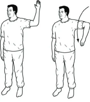
There is a number of active range motion exercises that can be performed targeted at
improving shoulder elbow and wrist rotation. A typical exercise aimed at the shoulder and
elbow movement is where the patient is in the standing position with elbow bent. The
patient then performs a rotation through the shoulder joint by lowering the hand towards
C h a p t e r 2 | B a c k g r o u n d
Figure 5 ‐ Active Range of Motion Exercises for the Arm (Ohio State University Medical Center 2007)
Active Assisted Range of Motion (AAROM) Exercises
Active assisted ranges of motion exercises are essentially anti‐gravity exercises whereby the
body part is supported and the patient is able to move freely. AAROM exercises are used
when the patient has some sensorimotor function, however does not have enough strength
to support the affected body part. This type exercises are able to assist with muscle control,
sensory skills while also acting as a good diagnostic tool used by the therapist for
determined the patient’s intermediate progress. As the patients movement is now visible
because the affected body part is not prohibited by its weight.
A common active assisted range of motion exercises is whereby the patient is laid flat on
their back while the therapist holds the arm vertical. This ensures that the weight of the arm
is distributed between the shoulder joint and the therapist allowing the patient to move
freely.
[image:22.595.232.391.73.252.2]
C h a p t e r 2 | B a c k g r o u n d
2.5 Virtual Reality Game’s Role in Rehabilitation
Virtual reality games are slowly being introduced into the rehabilitation process. The
reluctance for the rehabilitation units to adopt the new technology is largely due to the
expense of the current systems specifically designed for stroke rehabilitation. This is most
evident in the amount of stroke rehabilitations units that have included the Nintendo Wii in
the exercises for stroke patients (Cambourne 2008). The Nintendo Wii game console is
relatively inexpensive and enables an active range of motion in a virtual reality environment.
This game console requires the user to move a controller through a range of movement in
order to achieve tasks provided on a television screen. Virtual reality games enable more
interesting rehabilitation tasks to be created. Using a game environment also holds many
advantages over more traditional methods (J.W.Burke et al. 2008):
Varying level of difficulty
Having different level of difficulty is important to both game play and the rehabilitation
process, as it keeps the user interested while allowing them to always be challenged at their
level of progression. A varying level of difficulty can be implemented in a number of ways
such as change the amount to precision, speed or logical problem solving required in the
user.
Increased motivation
Rehabilitation is a goal‐oriented process, virtual reality games can provide more
intermediate goals for the user to achieve and it therefore increases motivation by
rewarding the user with a sense of achievement. This can be achieved as the game can
provide instant feedback and hence the user can measure their success in real time. Virtual
reality environments encourage greater levels of motivation, immersion and involvement
leading to a greater sense of presence in the game which has a consistent positive
correlation with the task preformed.
Intensive repetition
Within traditional rehabilitation methods repetition of exercise and therapy is vital to the
C h a p t e r 2 | B a c k g r o u n d
interesting and relative realistic two and three dimensional environments at an almost
subconscious level. Intensive repetition exercises performed in a virtual environment can
provided a smooth transition from simple to more complex tasks in the real world.
2.6 Conclusion
Stroke affects patients in a number of different ways depending on the severity of the
stroke and the type of stroke in which the patient suffers from. There are two main types of
stroke: ischemic and haemorrhaging. The most common type of stroke is ischemic caused
when a blood clot is formed in an artery or blood vessel in the brain. The less frequently
occurring type of stroke is haemorrhaging which is the result of a burst in the blood vessels
in the brain.
There are two main outcomes of stroke, hemiplegia and hemiparesis. Hemiplegia which is
the complete paralysis of one side and in most cases is completely revisable. Hemiparesis is
the main focus of this chapter which is the weakening of affected side of the body.
Stroke rehabilitation essentially evolves re‐training of parts of the brain to take the role of
the damaged areas due to the stroke. The rehabilitation of movement is mainly based on
exercises assisted by a physiotherapists and is aimed at addressing the recovery of
sensorimotor function in the upper and lower limbs.
Virtual reality games are slowly being introduced into the rehabilitation process and have a
great potential to improve its effectiveness. The reluctance for the rehabilitation units to
adopt the new technology is largely due to the expense of the current systems specifically
designed for stroke rehabilitation.
This chapter has provided a background into the causes and effect of stroke. It has outlined
the role of rehabilitation and basic concepts behind the exercises used by physiotherapists.
C h a p t e r 3 | T h e ‘ A n t i‐g r a v i t y ’ A r m
Chapter
3
The
"Anti
Gravity"
Arm
3.1 Introduction
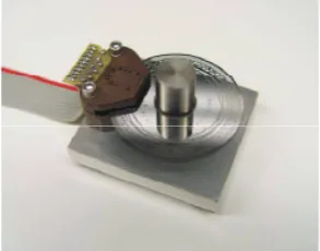
The ‘Anti Gravity’ arm was a prototype developed by Scott Carden in 2008. The device was
designed to facilitate a stroke patient's arm through a range of movements. The anti gravity
arm neutralise the weight of the device itself and the changing weights of the different
patient's arm. The design was quite successful in allowing a patient to move their arm is a
range of movement with comparatively little force. This chapter will briefly discuss the
structure of the anti gravity arm and method used for calculating it position. It will also
introduce other devices which have been developed for use in the rehabilitation of upper
extremities.
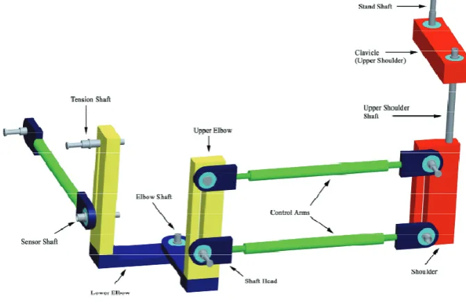
3.2 Structure
The structure of the ‘Anti Gravity’ arm is based on a modular design which allows certain
aspects of the antigravity set up to be changed. This includes both force generation and the
movement of the arm itself. Each module of the design is aimed at meeting different
movements of the human arm. There are four main sections antigravity arm (Figure 7); the
clavicle, shoulder and upper and lower elbow. These sessions are joined by pivots to create
the six different degrees of freedom which the antigravity arm is able to achieve.
[image:25.595.125.461.513.733.2]
C h a p t e r 3 | T h e ‘ A n t i‐g r a v i t y ’ A r m
The anti gravity prototype is quite a heavy apparatus with an aluminium and steel
construction. The design utilizes ball bearings mounted at each point of rotation help to
eliminate much of the friction. The prototype uses rubber bands in order to support the
weight of the device and the added weight of the patient's arm. The structure of device is
very flexible in its design, in that it enables different amount of tension to be applied by
changing the bands or changing the position of the tension shaft to achieve the desired
force. Adjusting tension shafts also changes the position of the control arms and hence the
changing characteristics of movement and lift (Carden 2008).
3.3 Position Acquisition
The anti gravity prototype has used Burnes 10 turn precision potentiometers to measure
each to the five degrees of motion. This resistance is measured by converting the analogue
voltage to a digital signal though the use of five ADC’s on the MPC‐MT‐2113 ARM
microcontroller (Figure 8). After the rotation has been measured, the three dimensional
coordinates of the endpoint of the device (tip of the hand) are calculated using the Denavit‐
Hartenberg forward kinematics equation which is processed on the microcontroller as a
series of matrix equations. The coordinates of the endpoint is then periodical sent to the
computer via a serial RS232 connection (Carden 2008).
Figure 8 ‐ MPC‐MT‐2113 ARM microcontroller (Carden 2008)
The endpoint coordinates are processed by the computer and display this point on the
screen in which the user is able to move. The main disadvantage of the interface is this
continually poling the microprocessor in order to receive the position data which is creating
bottleneck in transferring data and causing delays in the applications. While this software
does enable the user to interact with a virtual environment, the true position of the arm
C h a p t e r 3 | T h e ‘ A n t i‐g r a v i t y ’ A r m
Due to the nature and structure of the anti gravity arm, the centre position is arbitrary, as
different users and even seating positions can affect how the device will be positioned
relative to the users arm. The original design has overcome this issue by enabling the user to
centre the device through a menu provided by the microcontroller.
3.4 Similar devices
The basic concept behind the anti gravity arm is that the arm will be supported through a
range of movements without the user have to support the arms weight. There a number of
apparatus designed at achieving this, including the IntelliArm7 and T‐Wrex systems which
are discussed below.
3.4.1 IntelliArm7
The IntelliArm 7 is a similar device to the anti gravity arm, in that they are based on a partial
exoskeleton. The difference is that the IntelliArm is design to generate anatomic corrective
movement and simulate passive range of motion exercises ‘PROM’ (see chapter one), While
the anti gravity arm is design to assist with AAROM exercises and does not provide
corrective movement. This is where the device guides the patients arm to a waypoint while
prompting the user to a predetermined position.
[image:27.595.183.411.511.729.2]
C h a p t e r 3 | T h e ‘ A n t i‐g r a v i t y ’ A r m
The IntelliArm 7 has three active degrees of freedom (DOF) and two passive DOFs. There are
two active DOFs positioned at the elbow and one at the wrist. The two passive joints are in
the shoulder joint to simulate the movement of the clavicle. The active support system for
the IntelliArm 7 is achieved through the use of a combination of DC motors, cable and
electronic clutches.
One of the design key features of the device is its ability to predict the user's movement for
adding dynamic force based on the user's position and muscle strength. The software used
with the device is very advanced as it monitors all joints and displays direct feedback to the
user. Through the use of active assistance the user can interact with objects within a virtual
environment which increases user's awareness and involvement in applications such as
games and exercise routines.
The IntelliArm 7 is a very comprehensive therapy tool designed for use in a hospital
environment in part of a rehabilitation program. One of its major disadvantages is that the
device is very expense which prevents its use as part of home based therapy (Hyung‐Soon
Park 2008).
3.4.2 TWREX
The T‐WRWX is based upon the redesign of the Wilmington Robotic Exoskeleton (WREX)
originally designed by Dr. Tariq in 2005. The original design was focused creating as an
assistive device for children with neuromuscular weakness. The modified T‐WREX system is
adept at assisting with the functional limitations of stroke patients. It is a passive device
with five degrees of freedom and uses rubber bands in order to balance the users arm
(Housman et al. 2005).
C h a p t e r 3 | T h e ‘ A n t i‐g r a v i t y ’ A r m
Figure 10 ‐ T‐WREX (Housman et al. 2005)
The T‐WREX is used to track the patient’s movements and display the arm position in two
dimensions on screen. In addition to tracking the arms movement, the device also has a grip
sensor for measuring hand strength which is also incorporated in the games and analysis
software developed for the device. The system is developed using low cost components for
inexpensive home use without the requirement of a supervising therapist.
The T‐WREX system has been rigorously tested on a number stroke patient and has proven
that the system can reduce motor impairment of stroke survivors who suffer from
hemiparesis. The system has similar pitfalls as the anti gravity arm as they both require a
physiotherapist to perform the initial setup of the device and do not provide the facility of
remotely sending data about the user’s progress and activity levels.
3.5 Conclusion
The antigravity arm is a passive device designed to facilitate a stroke patient's arm through a
range of movements and is intended to assist with AROM exercises. The anti gravity arm
neutralizes the weight of the device itself and the changing weights of the different patient's
arms. It has a flexible modular design which enables certain components of the device to be
adjusted in order to change balancing forces and movement behavior. The force required to
balance the arm is achieved through rubber bands which also act to dampen the user’s
C h a p t e r 3 | T h e ‘ A n t i‐g r a v i t y ’ A r m
The rotation of each joint is measured using potentiometers and then is converted into a
digital signal using MPC‐MT‐2113 ARM microcontroller. The endpoint of the device is then
calculated and transferred to the computer via a serial RS232 connection.
This chapter also reviewed two other devices design to assist in the rehabilitation of the
arm; the IntelliArm 7 for PROM exercise and the T‐WRWX for AROM exercises.. IntelliArm 7
is perhaps the more sophisticated of the two as devices, as it incorporates an automatic
system for achieving active assistance and resistance. However the T‐WRWX, like the
C h a p t e r 5 | I n t e r f a c e S o f t w a r e D e v e l o p m e n t
Chapter
4
System
Development
4.1 Introduction
The system development is an important process which starts revaluating the aims of the
project and developing a general concept. After the concept has been formulated, it is
subdivide into related designed sections which can be addressed individually. The two main
designed section for this project as hardware and software.
The hardware design section is focused of determined the position of the users arm and
transferring to the computer in a useful format so that the computer monitor the
movement of the arm in real time. The software design section is comprised of three
subsections; the microcontroller software, computer interface software and the
games/application that utilize the data.
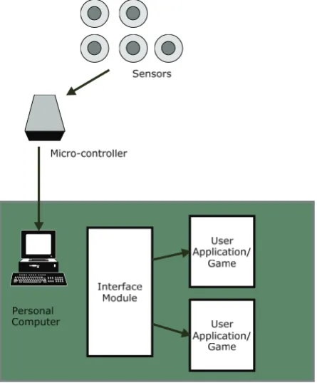
4.2 Concept
The basic function the interface module is to continuously read position data from the
sensors connected the ‘anti‐gravity’ arm’s microprocessor. The micro‐controller will then
convert the rotation into an integer for each joint and transfer it to the computer. The
interface will also enable the user to adjust setting and initialise the ‘anti‐gravity’ arm’s
centre position. Each time the application starts it will enable the user to save the load user
profiles. As shown in (Figure 11) the concept has been subdivided into the follow section
which can be address individually:
Hardware ‐ Sensors
‐ Micro‐controller
Software
‐ Micro‐controller software ‐ Interface module
‐ Game/Applications
C h a p t e r 5 | I n t e r f a c e S o f t w a r e D e v e l o p m e n t
Figure 11 ‐ Interface Concept
4.3 Hardware
In order to successfully measure the arm’s position and display it in a meaningful format,
there are a number of hardware issues that need to be resolved. From conceptual design
developed, the main hardware components include sensors for measuring the arms joint
rotation, processing these measurements and communications with the computer.
4.3.1 Sensors
The applications developed by the project will be used to directly evaluate the user’s ability
to perform certain exercises. For this reason it is important to accurately measure the user's
position. The most common method used for measuring and recording a person's position is
to use a motion capture studio.
Motion capture studios are mainly used by the entertainment industry for creating CGI
animations for movies and games. They work essentially by recording video footage of the
subject from multiple angles. The subject has uniquely coloured patches placed in key
positions over the body part, which they wish to animate. After the video footage has been
[image:32.595.187.410.77.346.2]C h a p t e r 5 | I n t e r f a c e S o f t w a r e D e v e l o p m e n t
which are then mapped to a rigid model. Using the shape, intensity and position, vectors
can be formed and translated into animation. Motion capture studios are very popular in
measuring a human’s movement as it provides the greatest degree of freedom, although is
no simple way of measuring joint rotation. However for this application the antigravity arm
acts as an exoskeleton whereby the rotation of the user's joints can be directly measured
from the rotation of the joints of the antigravity arm.
There are a few different ways in which the joints of the antigravity arm can be measured.
These are:
The Hall Effect rotational sensors which work by using a transducer that varies its
output voltage dependant the position of a rotating magnetic field. Hall Effect
rotation (Figure 12) sensors are light weight, compact devices that offer a high
degree of precision with a tight linearity tolerance typically around ±2%.
Figure 12 ‐ Honeywell Hall Effect Rotational Sensor (Honeywell)
Optical encoders are another possible sensor and work though the use of a photo
interrupter with a thin metal plate that break the light beam. The metal plate has a
large number of holes around the rim. As these holes passed through the photo
interrupter a pulse is generated which can be read by a microprocessor to
determine the angle. Optical encoders (Figure 13) offer a high degree of precision;
however they have to be calibrated each time the device is used to register centre
[image:33.595.273.368.375.518.2]C h a p t e r 5 | I n t e r f a c e S o f t w a r e D e v e l o p m e n t
Figure 13 ‐ Optical Encoder (Neamen 2007)
Potentiometers are commonly called variable resistors. The most common type
used for calculating rotation in robotics is the wire wound potentiometer (Figure
14) due to their degree of accuracy and tight linear tolerance. They consist of a
conductive wiper and thin gauged wire wrapped around a spindle, as the wiper
moves around the spindle the resistance is varied. By applying the rail voltage
across the spindle, the wipers voltage will vary across the range indicating the
rotation.
Figure 14 –Wire Wound Potentiometer
4.3.2 Data Acquisition
The output of the selected sensor will then have to be processed so that it can be
transmitted to the computer. The simplest means of doing this is to use a microprocessor to
[image:34.595.225.372.73.188.2] [image:34.595.225.375.458.568.2]C h a p t e r 5 | I n t e r f a c e S o f t w a r e D e v e l o p m e n t
The rotation signal is fed into the micro‐controller as an analogue voltage from the position
sensor. This voltage must then be converted to a digital number so that it can be read by the
computer and position of the arm can be calculated. The device used to perform this is
called an analogue‐to‐digital converter (ADC). The device converts the continuous signal to a
set discrete digital numbers through the use of a bank of logic circuitry which compares the
signal to varying reference voltage. The performance is classified by two characteristics: the
resolution and the sample rate. As the output from the sensor in this application is a slow
varying DC voltage, the affect of the sample rate is minimal. The accuracy of the interface is
completely dependent on the accuracy of the sensor and the resolution of the analogue‐to‐
digital converter. The most common resolutions used by ADCs are 8 bit, 10 bit and 12 bit.
The accuracy of the ADC measured in volts per step is described by the following equation.
2
Where
Given that all the considered miro‐controllers require 5 volt supply, 5v
Table 1 –Analogue‐to‐digital conversion accuracy
ADC resolution(M) Number of Increments(N) Volts per step(Q)
8 bit 256 19.5 mV/Step
10 bit 1024 4.8 mV/Step
12 bit 4096 1.2 mV/Step
The accuracy of converting an analogue voltage to a digital signal is directly related to the
number of increments used as shown in table 1. However increasing the resolution also has
C h a p t e r 5 | I n t e r f a c e S o f t w a r e D e v e l o p m e n t
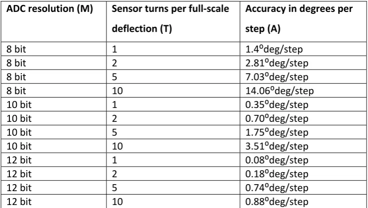
The accuracy of rotational sensors are described by the number of turns performed to
achieve full scale deflection. The expected accuracy of the complete system can be
determined by calculating the number of steps that the ADC can read per degree. (Neamen
2007)
360.
2
360.
Where
Accuracy in degrees per step
Table 2 ‐ System Accuracy
ADC resolution (M) Sensor turns per full‐scale
deflection (T)
Accuracy in degrees per
step (A)
8 bit 1 1.4⁰deg/step
8 bit 2 2.81⁰deg/step
8 bit 5 7.03⁰deg/step
8 bit 10 14.06⁰deg/step
10 bit 1 0.35⁰deg/step
10 bit 2 0.70⁰deg/step
10 bit 5 1.75⁰deg/step
10 bit 10 3.51⁰deg/step
12 bit 1 0.08⁰deg/step
12 bit 2 0.18⁰deg/step
12 bit 5 0.74⁰deg/step
12 bit 10 0.88⁰deg/step
From these results it is found that using a 12 bit analogue to digital converter with a single
turn rotation sensor it is possible to of measuring the rotational joints with the highest
degree of accuracy. However there are physical limitations that will need to be considered
in order to select the right devices, one of these limitations is the data rate achievable
between the computer and a microprocessor.
4.3.3 Device Communication
There are three main types of communication protocols used for interfacing a device with
[image:36.595.149.520.334.543.2]C h a p t e r 5 | I n t e r f a c e S o f t w a r e D e v e l o p m e n t
USB ‐ Universal Serial Bus
USB (Universal Serial Bus) in recent years has become the most popular medium for setting
up communication with peripheral devices. There are two versions of USB, USB 1.1 which
can support speed of up 12Mbit/s and USB 2.0 which can support 480Mbit/s. Due to the
success of USB a large number of micro‐processor manufactures have included USB
interface modules and code libraries into their products.
RS232 –Standard Serial Protocol
RS232 or serial connection is perhaps one of the old communication protocols still in use. It
was intended for speeds of up to 20,000 bits per second. The protocol also previsions for
parity bit and start/stop bit checking.
Ethernet – Local Area Network Standard
Ethernet is the most popular protocol for transfer data long distance. It can support 2
Gigabit/s speeds, however most micro‐controllers cannot support this speed. The main
reason that Ethernet was considered as an option is its simple integration with wireless
technologies.
4.3.4 Interface Hardware Selection
In considering the different hardware options, it is easy to identify the option which
achieves the highest accuracy and response. However there are number of non‐technical
aspects which have to be considered to ensure the best option is selected. These aspects
include:
Minimum requirements and physical limitations
Quality vs. Expense
The minimum requirements of the interface can be determined by considering in the
physical limitations of both the patients and the limitations of the antigravity arm device
itself. Due to the configuration of the antigravity arm, the maximum rotation that any joint
can achieve is 180°, therefore using sensors that offer more than a single turn has no
advantage. The applications for the interface are predominantly used for displaying the
C h a p t e r 5 | I n t e r f a c e S o f t w a r e D e v e l o p m e n t
rates, the human eye cannot distinguish between the refresh rates high than 25 frames per
second. Therefore there is no benefit in enabling the interface to obtain and transfer more
than 25 positions per second.
There were three rotational sensors considered for the project. The Hall Effect rotational
sensors and optical encoders were suggested to have the highest degree of precision. The
original design has used potentiometers is on each joint which is proven to be an
inexpensive option that still maintains a high degree of precision.
From the system accuracy table (Table 2), it was found that a single turn sensor with a 12bit
ADC will provide the most accurate solution. However micro‐controllers that offer 12bit
ADCs are typically less common and are significantly more expensive. Ideally for this
application the accuracy should be able to achieve at least 2° per step. The resolution of the
analogue to digital converter does not only affect the accuracy of measurement. It also
affects the data rate back to the computer, as the higher resolution of the ADC increases the
amount of data that needs to be sent back to the computer.
When considering these factors a single turn sensor with an 8 bit ADC would be an optimum
solution which will offer 1.4 degrees per step with the lowest amount of data required to be
transferred to the computer.
The original prototype design used Bournes 3590S, 10 turn precision potentiometers. These
potentiometers have a tolerance of 5% and linearity of 1.25%. In the interest of constructing
a working prototype as a proof of concept these potentiometers will not be replaced.
However this will increase the requirements of the analogue to digital converter as a 10 turn
potentiometer using an 8 bit ADC will only achieve 14° per step which is not accurate
enough to measure the user's movement. For this reason the minimum requirement for the
prototype will be a 10 bit ADC.
The communication interface can now be determined by calculating the minimum data rate.
This can be calculated by knowing the analogue to digital converter’s resolution in the
minimum refresh rate that has been selected above. Firstly the amount of data has to be
calculated, using a 10 bit ADC means that each joint rotation will be represented by 10 bits.
C h a p t e r 5 | I n t e r f a c e S o f t w a r e D e v e l o p m e n t
each sample. The minimum samples per second was found to be 25, therefore the interface
needs to send 1250 bits per second. This data rate is within the capability of the serial port.
The serial port interface is the most simple to implement and is also most commonly
available on micro‐controllers.
4.3.5 Microcontroller Selection
A micro‐controller is a low‐cost integrated circuit that contains memory, processing units
and input/out circuitry in a single unit. The purpose of microcontroller is to use information
collected from a variety of sensors to make decisions about how to control the output.
Micro‐controllers are used in numerous devices around the home and in industrial
applications. The main advantages of using micro‐controllers over dedicated hardware are:
Fast development.
Small circuitry layout.
Increased reliability through a smaller part count.
Ability to upgrade or provide fixes after the product has been shipped.
Low power consumption
The selection criteria for the micro‐controller, is that it must be a low cost, low development
time and reliable device that meets the minimum requirement established in section above.
The minimum requirements of the micro‐controller are:
Five 10 bit analogue‐to‐digital converters
Capable of achieving 25 samples per second
Capable of sending 1250 bits per second via a communication link to the computer.
There were three micro‐controller considered for the project, however given the relatively
low requirement for this application many more could have considered. The micro‐
controllers consider included:
ARM 7 LCP‐MT‐2138
Motorola MC68HC12
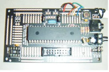
PICAXE microcontroller
C h a p t e r 5 | I n t e r f a c e S o f t w a r e D e v e l o p m e n t
4.3.5.1 ARM 7 LCPMT2138
The first micro‐controller considered for data acquisition was the ARM 7. This is the
microprocessor which was used in the original prototype with the LPC‐MT‐2138
development board. The ARM7 2138 series has a CPU frequency of 60MHz with 32kBytes of
Random Access Memory (RAM) and 512kBytes of flash memory for storage. This
microcontroller is very advanced, its main features are:
Speed operating at 60Mhz
LCD 16x2 display and buzzer
R