This is a repository copy of
A Multi-agent Framework for Dependable Adaptation of
Evolving System Architectures
.
White Rose Research Online URL for this paper:
http://eprints.whiterose.ac.uk/93151/
Version: Accepted Version
Proceedings Paper:
Johnson, Kenneth Harold Anthony, Sinha, Roopak, Calinescu, Radu
orcid.org/0000-0002-2678-9260 et al. (1 more author) (2015) A Multi-agent Framework for
Dependable Adaptation of Evolving System Architectures. In: 41st Euromicro Conference
on Software Engineering and Advanced Applications (SEAA). IEEE , pp. 159-166.
https://doi.org/10.1109/SEAA.2015.49
[email protected] https://eprints.whiterose.ac.uk/ Reuse
Items deposited in White Rose Research Online are protected by copyright, with all rights reserved unless indicated otherwise. They may be downloaded and/or printed for private study, or other acts as permitted by national copyright laws. The publisher or other rights holders may allow further reproduction and re-use of the full text version. This is indicated by the licence information on the White Rose Research Online record for the item.
Takedown
If you consider content in White Rose Research Online to be in breach of UK law, please notify us by
A Multi-Agent Framework for Dependable
Adaptation of Evolving System Architectures
Kenneth Johnson
∗Roopak Sinha
∗Radu Calinescu
†Ji Ruan
∗∗ School of Computer and Mathematical Sciences, Auckland University of Technology, Auckland, New Zealand † Department of Computer Science, University of York, York, United Kingdom
Abstract—We present a multi-agent framework for the formal verification of component-based systems after changes such as addition, removal and modification of components. The core of our approach is an Agent Verification Engine (AVE) that constructs evolvable Belief-Desire-Intention (BDI) agents to co-ordinate and plan the re-verification of component models after system changes. The engine provides BDI-agents with existing techniques for the compositional verification of component-based systems. We illustrate this integration for Satisfiability Modulo Theories (SMT) constraint analysis and demonstrate our frame-work on requirements arising from industrial control systems.
I. INTRODUCTION
Component-based software systems are increasingly com-mon, and include business- and safety-critical systems from domains as diverse as healthcare, transportation and finance [25]. Critical systems are expected to be reliable since down-time often results in a decrease of revenue or unavailability of essential services. Formal verification techniques such as model checking or automated theorem proving can be used to provide irrefutable proof of a system’s compliance to requirements by analysing mathematical models of the system against properties derived from the requirements.
Compositional verification techniques [3], [2] decompose the verification of a large, monolithic system model into a sequence of small verification steps that are applied to the components of the system, thus enabling formal verification of much larger systems. However, these approaches do not take into account the system’s runtime environment, where components are frequently added and updated or may un-expectedly fail. Agent-based modelling is widely used in safety or business critical systems as a means for intelligent adaptation in response to planned and unplanned runtime changes. This approach is well suited to adapt large scale cloud deployed systems [12], [26] and industrial manufacturing applications [20], [17] whose compliance to quality-of-service (QoS) requirements must be maintained during runtime.
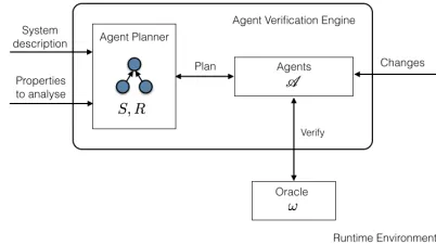
[image:2.612.341.542.195.308.2]In this paper, we introduce the Agent Verification Engine (AVE) which constructs agents to perceive, react, and adapt to runtime changes of a component-based system. These agents are based on the Belief-Desire-Intention (BDI) architecture [21], in which agents operate in terms of motivation and beliefs. BDI-agents have a formal basis in logic to formalize an agent’s decision making in an attempt to achieve its goals [9]. BDI-agents are constructed by AVE according to the system’s architecture and observe components to detect changes. When changes happen, agents perform verification tasks to verify the model of components against properties to determine compliance with system requirements.
Fig. 1. Agent Verification Engine (AVE) workflow
The main contributions of this paper are (a) an algebraic specification of an agent verification engine based on BDI-agents, (b) the integration of a satisfiability modulo theories (SMT) solver to provide agents with verification capabilities, (c) an application of the engine to a real-world industrial con-trol software case study, and (d) a prototype implementation of the agent verification engine using Jason AgentSpeak [4].
The rest of this paper is organised as follows. Section II provides key mathematical preliminaries. Section III formu-lates the agent verification engine algebraically and describes evolvable BDI-agent plans. Section IV integrates an existing SMT-based compositional verification approach into the en-gine. Section V applies the engine to analyse an industrial item sorting system. Section VI shows the effectiveness and scalability of our approach. Section VII discusses related work and Section VIII presents concluding remarks.
II. PRELIMINARIES
Assuming readers to have basic understanding of universal algebra [19] and BDI-agent architectures [21], [4], we define the following key tools and notations.
Signatures and Terms: A signature Σ consists of a sort s and a finite number of operation symbols f : sn → s for n ≥ 0. Symbols of the form c → S are signature constants. A signatureΣcontains the sortBoolwith constants true, f alse →Bool and names the standard logical connec-tives∧ and¬. Operation symbols of the form b:sn→Bool are Σ-predicates.Σ-terms are defined by the rules
t::=c1|. . .|cm|z|f1(t1, . . . , tm1)|. . .|fn(t1, . . . , tmn)
for constants c1, . . . , cm, variablez from the setZ, operation
The AgentSpeak Language: AgentSpeak [21] is an agent-oriented programming based on logic programming and the BDI architecture for autonomous agents. BDI-agents operate within an environment and receive continuous input percep-tions. Agents respond by performing actions that affect the environment. The beliefs, desires and intentions of an agent correspond with the agent’s informational, motivational and decision making components that comprise its mental state.
Beliefs: An agent’s belief is constructed from predicate terms as follows. If t =t1, . . . , tn is a tuple of Σ-terms then b(t)
is a belief atom for the predicate symbol b. If b(t) and c(t)
are belief atoms then ¬b(t), b(t)∧c(t) are beliefs. Beliefs represent the information available to the agent and are stored in its belief baseB.
Goals: Ifg is a predicate symbol andt=t1, . . . , tn a tuple
ofΣ-terms then!g(t)is anachievement goalan agent aims to achieve and?g(t)is atest goalthat tests ifg(t)is a true belief. Acquiring a new belief or goal creates atrigger eventwithin an agent. Ifb(t)is a belief atom then+b(t),−b(t)are triggering events corresponding to the addition and removal of beliefs. Similarly, +!g(t), −!g(t) and+?g(t),−?g(t) correspond to the addition and removal of achievement and test goals, respectively.
III. AGENTVERIFICATIONENGINE
This section algebraically specifies the Agent Verification Engine (AVE). The engine’s workflow is depicted in Figure 1 and comprises the agent planner, that reads an algebraic system specification S and requirements R, a set A of BDI-agents
constructed by the agent planner to verify components of S and an oracle ω. The workflow has two phases. In the agent construction phase, the agent planner constructs a set A = {αt1, . . . , αtn}of BDI-agents for componentst1, . . . , tnof the
system S. Each agent is constructed with a plan library to determine compliance of its component with the requirements given by R. The agent invokes an external oracle ω which represents a compositional verificationserviceto determine the component’s satisfaction of requirements. In theagent runtime phase, an agent perceives localised component changes t′ in
the runtime environment and notifies the agent planner. The agent planner transforms S by performing the corresponding term substitution S′=S[t′/t] of the agent’s component term
t with the new component term t′ to obtain S′. The agent planner usest′ to update the agent’s beliefs and plan library.
A. The Oracle
LetM be a set of component models,Pa set of properties
andV a set of values. Theoracleis an automated process that accepts as input a verification taskw= (m, g, a)from the set W =M ×P×[P →V] and is modelled mathematically
by the total function ω:W →V such that
ω(m, g, a) =the valuev obtained from the process (1) of verifying propertyg on modelm under assumptions ofa
for model m ∈ M, g ∈ P and v ∈ V and the map a : P → V of properties to verification values. The oracle is
programmed to always terminate, potentially due to failure. If a failure occurs, then a special unverified value uis returned
by the service. We extend the set of values to include this element by settingV =V ∪ {u}.
Our choice of notation in (1) generalisesassume-guarantee [11], [14] model checking approaches to include decom-position techniques used in formal analysis of component-based systems. In assume-guarantee reasoning, a monolithic model mis decomposed into smaller, more manageable mod-els m1, . . . , mq. Each model mi is associated with a
prop-erty ai ∈ P, formalising requirements of the component.
Component-wise verification is performed in a sequence of steps whereby the verification of property ai on model mi obtains a verification value vi ∈ V. In symbols, we write
vi |=ai, for the modelmi, 1≤i ≤q. We denote the list of assumptions and verification results obtained by component-wise verification as a. Using the assume-guarantee approach, the system requirements formalised as the property g ∈ P
for the monolithic modelmhas verification resultv under the assumptions a. In symbols, we writev|=g.
B. Agent Construction Phase
We give an algebraic specification of component-based systems and use their inductive properties to derive the agent planner’s construction of the agent setA.
Specifying Component-Based Systems: A component sig-nature Σ is a finite set C of component sorts that repre-sent parts of a system and a set {f1, . . . , fn} of operations
to be performed on components. By choosing some basic components c1, . . . , cm, e.g. constants in Σ and applying a
sequence of operations, we form a component-based system as a high-level syntacticcomponent term S. The term defines the hierarchical structure of a component-based system by expressing the sequence of operations carried out in the construction of the system and specifies the order in which they are applied. Let the set of all component terms over the signatureΣbe denoted asC(Σ). For example, the component termcomp(c1, comp(c2, c3))inC(Σ)is formed from the
com-position of basic component c1 and the composition of basic
components c2 andc3, wherecomp:C(Σ)×C(Σ)→C(Σ)
is an operation in Σ. The inductive properties of component terms are a natural data structure for specifying BDI-agent verification plans.
Each component c ∈ C(Σ) is associated with a model m∈M and a propertyg∈P formulated fromR.
Agent Plans for Basic Components: Letc be a basic com-ponent of the comcom-ponent signature Σ,m∈ M a component
model and g∈P a property. The agent planner constructs a
BDI-agent αc with initial beliefs
Bc={model(m),property(g)} (2)
where the predicates modelandproperty specify agentαc’s belief of the component model m and property g. Initially, the agent has the achievement goal !verify to determine the verification resultv∈V of propertygfor modelm. We define
the context expression
Ec=model(M)∧property(G) (3)
constructed by the agent planner. This plan has the form
+verif y:Ec ←?model(M)∧?property(G)∧
ω(M, G, V)∧+result(V). (4)
Since the initial belief base (2) of αc satisfies the plan’s contextEc, the agent’s goal!verify triggers plan (4). The test goals?model(M)and?property(G)unify the model mand property g with variables M and G respectively, according to the agent’s beliefs (2). The agent αc performs the action ω(M, G, V)and invokes the oracle to computev=ω(m, g, η), with the null functionη :∅ → ∅specifying that no assumptions are required for the computation. The result v is unified with variable V and+result(V)adds the value to the belief base with the predicate symbol result.
Agent Plans for Composite Components: We give an inductive definition of the plans for agent αt assigned to the component term t =f(t1, . . . , tm) with sub-components
t1, . . . , tm and the operation symbol f ∈ Σ. The agent
has beliefs of its component model m and property g, and thus the initial belief base of αt is set as Bt = {model(m),property(g)}, similar to (2).
In general, the verification result v |= g for model m of agent αt is dependent upon the verification values obtained by agents At={αt
1, . . . , αtm} for the sub-terms oft. Agent
αt therefore must communicate with each agent in At and
construct assumptions a : P → V to be supplied to the
oracle. To coordinate with agents αt1, . . . , αtm, agent αt is
constructed with the plan
+!queryagents:true← (5)
send(t1, givep, A1)∧ · · · ∧send(tm, givep, Am)
∧send(t1, givev, V1)∧ · · · ∧send(tm, givev, Vm)
which asks each sub-component agent αti to retrieve the
verification task information stored within its belief base. The properties a1, . . . , am in P and values v1, . . . , vm in V are
unified with variables A1, . . . , Am and V1, . . . , Vm
respec-tively. They are used to construct the assumption function a:{a1, . . . , am} → {v1, . . . , vm} such that
a(ai) =vi. (6)
To facilitate communication with αt, each agent αti is
constructed with the plan
+?givep: true←?property(A) (7)
∧send(t, propertyti(A)).
by the agent planner, which is triggered whenever its mental state is changed to the test goal ?givep, for1≤i≤m.
The plan body of (7) contains a specialsendaction which enables transmission of messages between agents using the Knowledge Query and Manipulation Language (KQML) [16] which expresses an agent’s intention for sending a message. Agents send messages for two purposes: i) to change the receiver’s beliefs, or ii) to change the receiver’s goals. In the plan body of (7), agentαti’s property belief is unified with the
variable P and sent to agent αt, who receives the belief and adds it to Bt. Similarly, the verification value obtained from
the oracle ω byαti is sent toαtby the plan
+?givev:true←?result(V)∧send(t, resultti(V)). (8)
The goal ?result(V)is complete only whenαti completes its
verification task and resultti(V)is added to its belief base.
For the composite component represented by the compo-nent term t with sub-termst1, . . . , tm, the context expression
(3) is extended to
Et′= Et∧propertyt1(A1)∧ · · · ∧propertytm(Am) (9) ∧resultt1(V1)∧ · · · ∧resulttm(Vm)
to ensure the values from agents αt1, . . . , αtm have been
received. The agent planner formulates two plans so that agent αt can achieve its verification goal !verify. The first plan is applicable whenever αt has not obtained values from agents αt1, . . . , αtm. In this context, the plan
+!verif y:¬Et′←!queryagents∧!verif y
comprises the achievement subgoal !queryagentswhich trig-gers plan (5) and continues to attempt the achievement!verify. In the context of receiving values from all sub-component agents, the plan invoked to achieve !verify is
+verif y: Et′←?model(M)∧?property(G) (10)
∧?propertyt1(A1) ∧ · · · ∧?propertytm(Am) ∧?resultt1(V1) ∧ · · · ∧?resulttm(Vm)
∧ ω(M, G, V, A1, . . . , Am, V1, . . . , Vm)
∧ +result(V).
comprising additional test goals unifying A1, . . . , Am and
V1, . . . , Vm with properties and values from the verification
tasks of agents αt1, . . . , αtm. The properties and values
con-struct the assumption function adefined in (6) used as input for action ω(M, G, V, P1, . . . , Pm, V1, . . . , Vm), invoking the
external oracle to computev =ω(m, g,a). The variableV is unified with the value v and stored in the agent’s belief base with predicate symbol result.
C. Agent Runtime Phase
Runtime environments are dynamic and changes such as the addition, removal and modification of components occur in rapid succession. In this section, we specify plans enabling an agent to sense localised changes of the components modelled by their verification task. When a component change occurs, the agent is required to adapt and evolve its beliefs and behaviour during system operation in order to maintain a verification task that correlates to the actual state of the system. Formally, agent αt is constructed with the plan
+!detect:true←sense∧!detect. (11)
which executes the action sense to detect changes in the component t ∈ C(Σ). Component change detection only occurs afterαtachieves its initial verification goal. We extend the agent’s verification plan by appending the achievement goal
!detectto the plan bodies listed in (4) and (10).
Agent Change Perceptions: The agent actionsensenotifies the engine that the system represented algebraically by the component term S is updated according to a component change sensed in the runtime environment. Mathematically, a component change is modelled as a component termt′∈C(Σ)
with an associated model m′ ∈ M and property g′ ∈ P.
S and associated model and property. It then notifies agent αt of the new model m′ and property g′, and finally adds a
change perceptionto the belief base of agentαtcorresponding to addition, removal or modification changes.
Modification Component Change: Change perceptions are handled by agents in the following cases. When component ti of the component t ≡ f(t1, . . . , tm) for 1 ≤ i ≤ m
is modified, a change perception modif ied is issued by the engine to agent αti. In this case, the engine first updates the
component model and property to m′
ti and g ′
ti respectively.
The engine updates the belief baseBt
i of the agent, replacing
its model and property beliefs with information of the new verification task model(m′
ti)andproperty(g ′
ti), respectively.
The engine’s change perception triggers the belief addition event+modif iedin the agent and is handled by the plan
+modified :true ←!verif y∧!notif y.
supplied by the agent planner. The agent proceeds to call the oracle to verify its modified task, providing the agent with a new beliefresult(V). Next, the agent achieves the goal!notify to notify agent αt that re-verification is complete. The plan
+!notify :true←send(t,!reverif yti). (12)
communicates the !reverif yti achievement goal to agent αt.
Agentαtattempts to achieve this goal using the plan
+!reverifyti :true← −resultti∧ −propertyti (13) ∧send(ti, givep, Ai)
∧send(ti, givev, Vi)∧!verif y∧!notif y.
which obtains the modified property a′
i and updated verifi-cation result v′
i from αti. The !verify goal uses the updated
assumptions functiona′:P →V to invoke the oracle where
a′(aj) = v′
i if aj=ai, a(aj) otherwise,
and notifies agents that re-verification has occurred.
Addition Component Change: In the general case, the component term t = f(t1, . . . , tm) has m sub-components.
The addition of the new component tm+1 totis specified by
the component termt′ =f(t
1, . . . , tm, tm+1). Mathematically,
we define the substitution operation
S′=S[f(t1, . . . , tm)/f(t1, . . . , tm, tm+1)] (14)
to replace instances of t with t′ in the component term
representationSto obtainS′. When the system representation
is updated, the engine adds the change perception add(tm+1)
to agentαt’s belief base, triggering a belief addition event that is handled accordingly by the plan
+add(T) :true←create(T) ∧ replan
∧!verif y∧!notif y.
The action create(T)invokes the agent planner to construct a new agent αtm+1 and assign it the verification task w
associated with the new component tm+1. Once constructed,
the agent completes its initial achievement goal !verify. The action replan described in the next section is used by αt to take into account the added component. Once αtobtains new plans it re-verifies to take into account the new component. The goal !notify ensures all relevant agents are notified.
Removal Component Change: A componenttiis removed from t = f(t1, . . . , ti, . . . , tm), resulting in a new
com-ponent term t′ = f(t
1, . . . , ti−1, ti+1, . . . , tm). The term
substitution operation (14) is applied to S such that S′ =
S[f(t1, . . . , ti, . . . , tm)/f(t1, . . . , ti−1, ti+1, . . . , tm)]replaces
instances of t with t′ in S, forming the component term S′.
When the system representation is updated, the engine adds the change perception removeti to agent αt’s belief base,
triggering a belief addition event handled by the plan
+removeti :true← −propertyti∧ −resultti∧ stopti ∧ replan∧!verif y∧!notif y.
which removes agent αt’s beliefs regarding the verification result and property obtained from agentαti. The actionstopti
terminates and removes agent αti from the AVE. The agent
planreplanrequests new plans that enableαtto reverify their verification task and notify all relevant agents.
Agent Evolution: Agent action replan requests advice from the planner after a change. The planner modifies the agent’s plan library as follows. Given the component term t′
obtained by adding or removing the sub-component term ti from t = f(t1, . . . , ti, . . . , tm), the agent planner constructs
• a new !queryagents plan body (5), adding or remov-ing actionssend(ti, givep, Ai)andsend(ti, givev, Vi) re-questing agent αti’s property and verification value. This
corresponds to constructing the assumption function in (6).
• a context rule (9), adding or removingpropertyti(Ai)and
resultti(Vi)as belief requirements for verification, • a verification plan body (10), adding or removing test goals
?propertyti(Ai)and?testti(Vi). The parameter listing in
the oracle invocation is accordingly updated to add or remove parametersPi andVi.
• a re-verification plan (13), adding and removing plans corresponding to sub-components dependencies.
When the agent receives the new plans, the agent reini-tialises and attempts to achieve their initial verification goal.
Re-verification Policies: Plans (12) and (13) perform re-verification that essentially follow recently introduced incre-mental verification techniques [13], [14] based on component dependencies defined by the system’s architecture. By using a BDI-agent approach, these techniques are extendable to gen-eralised verification policies comprising programmable agent behaviours to perform remedial actions taken in response to component change. Agent behaviour can express policies to send conditional notifications only when their component be-comes non-compliant to requirements after a change, perform verification steps involving other oracles, or notify other agents specified by the application domain requirements.
IV. A COMPOSITIONALAPPROACH TOSMT
We instantiate AVE with an existing SMT-based technique. The following concepts are defined in [13] and reproduced for completeness.
Component Models: To integrate an SMT verification service with the engine we defineM =P(Z)+, such that each
• Zci ∈ P(Z), for each basic component termci such that
models are pairwise disjointZci∩Zcj =∅, fori6=j. • Zf(t1,...,tm) = ∪
m
i=1Zti for each operation f ∈ Σ and
component termst1, . . . , tm.
Component Properties: Let P = F(Γ, Z) such that
component requirements are quantifier-free first order formulae over the signatureΓ, defined inductively by the rules
φ::=t1=t2|r1(t1, . . . , tn1)| · · · |rm(t1, . . . , tnm)| ¬φ1|φ1∧φ2|φ1∨φ2
wheret1 andt2 are terms, andφ1 andφ2 are formulae.
We often display the variables that appear in a formula by writing φ(z) to mean that the formulaφ has at least one instance of the variables in the tuple z= (z1, . . . , zp).
SMT Resolution: Satisfiability modulo theories represent a class of theoretical techniques and practical tools that de-termine the satisfiability of a formula expressed in terms of tests and operations in a signature Γ. An SMT technique smt : F(Γ, Z) → [Z → V] is applied to the formula φ(z)
in order to compute and return an assignment v : Z → V
of values from the set V to the variables in z, such that the formula is satisfied. In symbols, we write v |= φ(z) ⇐⇒ [[φ(z)]](v) =truewherev=smt(φ(z)). If no such v exists then the unsatisfiable assignment u : Z → V is returned.
We note the empty formula ǫ is valid (i.e. satisfiable by all assignment mappings).
The requirements function R : C(Σ) → P supplied to
the agent verification engine associates each component term t with a logical formula φt such that var(φt) ⊆ Zt where var(φt)is the set of variables inφt andZt is the component model oft. We use the inductive properties of component terms to compute the conjunction φ=φt1∧ · · · ∧φtm of formulae
associated to the components t1, . . . , tm of S. By resolving
φ using smt, we get an assignment a : P → V of values
from V to variables in φ such that system requirements R
are satisfied. We also define the function mono : C(Σ) →
F(Γ, Z)such thatmono(t)is the monolithic formula oft, by induction over the structure of component terms.
Lett be a component term inC(Σ).
Base case: for t ≡ ci the basic component ci, we have mono(ci) =φci.
Inductive step: for t≡f(t1, . . . , tm)with sub-components
t1, . . . , tm and operation symbolf ∈Σ, we havemono(t) =
φf(t1,...,tm)∧(∧
m
i=1mono(φti)).
Compositional SMT Resolution: As the component-based system S typically contains a large number of components and requirements, resolving a monolithic formula mono(S)
involves a huge constraint problem and is generally unfeasible for a single agent to complete during runtime. Instead, we describe a compositional approach based on the results of [13], [24] which constructs smaller resolution steps to be carried out independently. The solutions obtained in each step are combined to form a solution for the monolithic formula.
The resolution of the conjunctionφ1(y)∧φ2(z)of
indepen-dent formulae (no shared variables) may be decomposed into two smaller steps a1 = smt(φ1(y)) and a2 = smt(φ2(z)),
combined using the operation ⊕: [P →V]2 →[P →V]
such that (a1⊕a2)(z) =a1(z)ifz∈zanda2(z)otherwise.
We can prove that a1 ⊕a2 |= φ1(y)∧φ2(z) (cf. Lemma
4.1 [13]). We extend this observation to n > 1 indepen-dent logical formulae φ1, . . . , φn and construct an assignment
v |= ∧n
i=1φi through a sequence of independent resolution
steps v1|=φ1, . . . , vn|=φn. (cf. Theorem 4.1 [13]).
The SMT Oracle: Compositional SMT resolution serves as the basis for instantiating the assume-guarantee oracle ω specified by (1) to perform compositional SMT resolution. The oracle accepts as input a verification task comprising
• mapping a:{φ1, . . . , φn} → {v1, . . . , vn} of independent
logical formulae in F(Γ, Z) to values in V representing
assumptions such vi |= φi for φi ∈ dom(a) and vi ∈
range(a),
• g∈F(Γ, Z), independent of each formula indom(a),
• model m = var(g)∪(∪i∈{1,...,n}var(ai)), the union of
the variable sets forg anda1, . . . , an.
We model the oracle as the total function ω:W →V as
ω(m, g,a) =smt(g)⊕(⊕n
i=1vi) (15)
that performs smt resolution to compute an assignment of values in V to the model variables in m that satisfies the
conjunction g∧a1∧ · · · ∧an of logical formulae. Thus, we
conclude ω(m, g,a)|=g∧(∧n i=1ai).
V. CASESTUDY
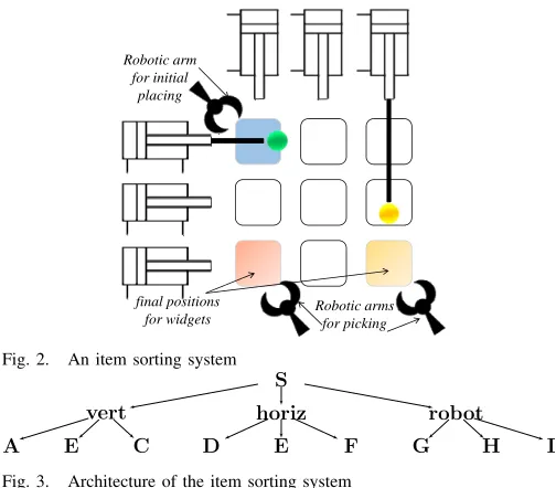
We introduce an industrial control system to illustrate our agent-based verification engine. Figure 2 depicts an item sorting system (ISS), typically used to sort high volume item streams within systems such as airport baggage handling and food packaging. Items are placed in an initial position by a robotic arm. Horizontal and vertical pushers use sensors to detect items and then direct them towards user-specified end-points. Additional robotic arms remove items from the end-points. The system software is written using the IEC 61499 [18] language, which enables component-based design where components contain finitely nested networks of (sub) components. Figure 3 shows the architecture of the ISS. The system S comprises components vert, horiz and robot, rep-resenting the control programs for the vertical and horizontal pushers, and the robotic arms, respectively. Each component has three sub-components labelled from AtoI.
Components of IEC 61499 programs execute on devices such as programmable logic controllers (PLCs). Components deployed onto the same PLC communicate using faster local mechanisms such as shared buffers. Components on different PLCs communicate using networks like Ethernet. For the ISS, which handles high item volumes, system speed can be significantly reduced if critical path sub-components like communicating pushers execute on different PLCs. Also, the ISS can be made more dependable by deploying multiple instances of sub-components A−I across available PLCs, numbered 1 to p (p ≥ 2), according to the following high-level requirementsR:
Robotic arms for picking Robotic arm
for initial placing
[image:7.612.48.300.53.274.2]final positions for widgets
Fig. 2. An item sorting system
A E C E
vert
G
F H I
robot S
horiz
D
Fig. 3. Architecture of the item sorting system
R3 Ghas exactly 3 instances on PLC 2 R4 H must not be deployed on PLC 1
R5 all instances ofD,E andFare identically distributed Thedeployment configuration problemdetermines a distri-bution of component instances of the ISSSacrosspPLCs to satisfy the high-level requirements R.
System Specification in AVE:We define a component signa-tureΣand express an algebraic specification of the system ar-chitecture depicted in Figure 3. Let the set of component terms be denoted asC. We set the basic components of the system
A, . . . ,Iand define an operation symbolc:C×C→C. For the ISS, we have the component term
S≡c(vert, c(horiz,robot)) (16) where, vert ≡ c(A, c(B,C)), horiz ≡ c(D, c(E,F)) and
robot≡c(G, c(H,I)).
Component models: To apply the compositional SMT reso-lution technique described in Section IV to the deployment configuration problem, we model sub-components A, . . . ,I
by finite sets ZA, . . . , ZI of variables. E.g., A is modelled by the set ZA ={Az1, . . . ,Azp} of integer-typed variables from the set Z such that the assignment Azi=nmodels the deployment of ninstances of componentAonto theithPLC. By definition, we have the modelZS=Zvert∪Zhoriz∪Zrobot associated with the component term S, where Zvert=ZA∪
ZB∪ZC,Zhoriz=ZD∪ZE∪ZFandZrobot =ZG∪ZH∪ZI.
Requirements Specification We define a mapping φ :
C(Σ) → F(Γ, Z) by formalising requirements R1 - R5 of the ISS architecture as logical formulae over integer-type variables to be associated with components of S. Let Γ be a signature comprising sorts for integers and Boolean, symbols for the standard arithmetic operations, equality and inequality predicates. Initially, we setφt=ǫ, that signifies the case where componenttis not constrained. RequirementR1sets the range of deployed instances for each sub-component of S between 1 and 10, with non-negative number of instances over any PLC. For sub-component A, we express this requirement as
the formula
φ1A:= p
^
i=1
Azi≥0∧
p
X
i=1
Azi ≥1∧
p
X
i=1
Azi ≤10. (17) Similarly, all other sub-componentsB−Iare assigned formu-lae φ1
B−φ1I respectively. Requirement R2 further constrains the deployment, and is expressed asφ2
A:=
Pp
i=1Azi≥4. We
add this formula to the existing formula for R1 by assigning φA:=φ1
A∧φ2A. We assign simular formulaeφB:=φ1B∧φ2B and φC := φ1
C ∧ φ2C for sub-components B and C. R3 is formalised as φ2
G := (Gz2 = 4) and we construct φG:=φ1
G∧φ2G, using the formulaφ1GformalisingR1forG. For R4 we specify φ2
H := (Hz1 = 0)and add this formula to the existing requirements by assigning φH := φ1
H∧φ2H. Lastly, we formalise RequirementR5which states that the sub-components of D,E and Fmust have identical distributions of instances across the PLCs. We define the formula
φvert:=
p
^
i=1
(Dzi=Ezi)∧(Fzi=Ezi) (18) where the model for vert comprises variables from its sub-component models ZD,ZE, andZF.
VI. IMPLEMENTATION ANDSIMULATION
We developed a generic multi-agent simulator of the agent verification engine as a open-source Java application. The engine’s implementation is based on Jason AgentSpeak [4]. Jason has a theoretical basis which is amenable to our formal approach for system adaptation and has built-in, extensible support for multi-agent system distribution over networks. We used Jason’s standard architecture for agent perceptions, inter-communication and actions. The AVE’s implementation comprises the following core classes
• RunTimeEnvironment<M,P,V>simulates perceptible component changes within the system’s runtime environ-ment and executes agent actions (M for models, P for properties andVfor verification results)
• Engine<M,P,V> maintains the system representation and compositional verification technique
• AgentPlanner<M,P,V>constructs agents and provides new plans after changes occur.
• CompVerify, a compositional verification paradigm pro-viding abstract methods add, modify andremove for updating the system’s algebraic specification.
Agent Verification Engine for the ISS: We instantiated AVE for the deployment configuration problem for the ISS as follows. First, Z3CompVerify, a concrete class utilising the compositional SMT approach described in Section IV was developed. The oracleωdefined by (15) is implemented using the Microsoft satisfiability modulo theories solver Z3 [8]. AVE was also provided with S, the architecture (16) of the ISS, as well as a mapping φ: C(Σ) →F(Γ, Z) that assigns logical formulae to components of the system.
When the engine receives these inputs, the agent planner constructs the necessary agents that co-operate to solve the deployment configuration problem. Figure 4 depicts a tree comprising ten agents in the set A constructed by the agent
αA(φA) αB(φB) αC(φC)
αvert
αG(φG) αH(φH) αI(φI)
αrobot
αS
[image:8.612.321.571.51.181.2]αhoriz(φD∧φE∧φF)
Fig. 4. ISS Agent Tree
TABLE I. AN ASSIGNMENT MAPPING SATISFYING ALLISS
REQUIREMENT INRFOR2 PLCS.
αA αB αC αvert αG αH αI
vS A B C D E F G H I
z1 1 4 2 1 1 1 0 0 1
z2 3 0 2 1 1 1 3 1 0
the name of the agent corresponding to a component in the ISS. The logical formulae to be resolved by the agent using the oracle are written in parenthesis. The formulaφvertdefined in (18) shares variables with its sub-component formulae φD, φE and φF. None of these formulae can be resolved independently thus the engine assigns the task of resolving φvert∧φD∧φE∧φF to agentαvert. The edges of the tree denote communication links between agents in which queries, properties and values are transmitted according to plans (5), (7) and (8) respectively.
Once the engine has been initialised, agents inA attempt
to achieve their verification goal. We consider this process for agent αA as follows. The agent has initial beliefsmodel(ZA)
and property(φA). It then attempts to achieve goal !verify using plan (10) by invokingω(ZA, φA, η)to obtain assignment vA ={Az1 →1,Az1→ 3}, storing the belief result(vA). It also attempts the achievement goal !detect defined in (11) to sense changes in component Aduring runtime.
The configuration problem is resolved when the result belief is stored by αS.αS carries out the following steps for this purpose. αS first queries the agents αvert, αhoriz and αrobot and forms the assumption functiona:P →V such
that a(φvert) =vvert, a(φhoriz) =vhoriz, and a(φrobot) =
vrobot. αS then invokes the oracle vS = ω(ZS, ǫ, a), where ZS is the component model of S, ǫ is the empty formula. Finally, αS stores+result(vS)in its belief base.
Table I depicts the valuevSobtained by the SMT process carried out by the oracle. The agent’s belief represents one possible assignment mapping to satisfy all requirements inR.
Experimental Results
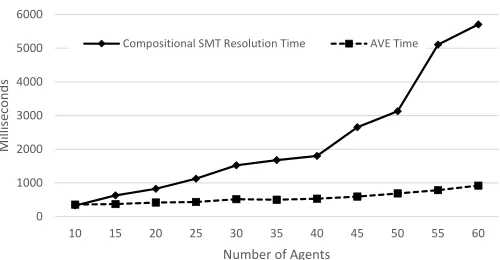
We evaluated the performance of AVE by running a series of experiments starting with the ISS architecture shown in Figure 3 and subsequently increasing the system size by five components at each step, corresponding to an increase of 5 agents and 50 variables in the Z3 specification of the system requirements (assuming 10 available PLCs). The experiments hence considered system sizes containing between 10 and 60 agents. A standard PC running Windows 7 Enterprise 64-bits with an Intel i7 2.1GHz Processor and 16 GB RAM was used for the tests. We measured the time forαSto acquire the belief result(vS) and compared it to the cumulative time across all oracle invocations, corresponding to the time needed to complete minimal number of steps to resolve the deployment configuration problem using standard compositional SMT res-olution. The results of this experiment are presented in Figure 5. All runs completed under 7 seconds. For small system sizes, the difference in speed of the two approaches is negligible. As
0 1000 2000 3000 4000 5000 6000
10 15 20 25 30 35 40 45 50 55 60
Mi
ll
is
e
co
n
d
s
Number of Agents
Compositional SMT Resolution Time AVE Time
Fig. 5. Configuration using Compositional SMT resolution and AVE
the system grows with additional components, AVE benefits from concurrent oracle invocations by the agents.
We also carried out the following experiments to evaluate the performance of our implementation for re-configuration after a system change is perceived by an agent.
1. Adding a Robotic Arm: The ISS requires an additional robotic arm to pick up items from a new end-point and the runtime environment simulates the addition of a new component R to the system. The component is modelled by the variable set ZR and its requirements are formalised by the standard logical formula φR = φ1
R as defined in (17). The agent verification engine performs the following steps. First, a substitution on the component term S is performed, obtaining S′≡S[robot/c(c(G, c(H,I)),R)]andadd(R)is added to αrobot belief base. Next, agent αrobot issues the action tocreate(R). The agent planner then submits new plans toαrobot, who invokes the oracle with assumptions fromαG to αI andαR. Agent αR obtains a new belief of the result. Finally,αrobotnotifiesαS, resulting in a new result belief for αS that includes the new verification result.
Figure 6 shows AVE consistently took about 37 millisec-onds to re-configure the system, ranging in size from 10 to 60 agents. In contrast, global reconfiguration of the entire system took increasingly longer as system size increased.
2. Modifying Requirements:We considered updated require-ments to change the deployment of the pushers over available PLCs. Such updates may happen often for the ISS, in order to react to changing item volumes and types. As Figure 6 shows, the re-configuration effort grew from about 67 milliseconds to 110 milliseconds for systems sized from 10 to 60 agents. In contrast, a complete re-configuration can take as much as nine times longer to reverify, requiring 1000 milliseconds to completely reverify the largest system containing 60 agents. Experiments to compare re-verification time after an agent removal due to component failure showed that on average it takes 58 ms for agent αS to obtain an updated result belief, whereas global reconfiguration takes 897 ms on average, for systems containing 10 to 60 agents.
VII. RELATEDWORK
[image:8.612.51.293.53.176.2]0 100 200 300 400 500 600 700 800 900 1000
10 20 30 40 50 60
Mi
ll
is
e
co
n
d
s
Number of agents
AVE (add component) Global (add component)
[image:9.612.51.303.53.165.2]
AVE (add component) Global (add component) AVE (property update) Global (property update)
Fig. 6. Running time of AVE versus full compositional verification
paper but by contrast, our work delegates verification tasks to agents rather than handling them in a centralised way. In [23], two configuration protocols for deploying a cloud application over multiple virtual machines are proposed and verified using formal methods. In contrast to our work, the protocols proposed in this article do not take into account component failures and subsequent re-configuration actions. In [5], a reconfiguration protocol is proposed that can handle any number of failures during a reconfiguration. This protocol expects reconfiguration decisions to be made before-hand, unlike our approach which uses agents to make reconfigura-tion decisions based on changes in the system architecture, requirements, or device availability. Another approach that incorporates agent technology is Lira [7], a light-weight, agent-based reconfiguration engine. Each component in a given distributed software system has a unique agent associated with it. An agent handles reconfiguration requests for its associated component. RECoMa [10] is a configuration manager can help find appropriate computer platforms to deploy software agents of a multi-agent system. All available devices on which available components can be deployed are treated as equal, each capable of deploying the components allocated to it. However, our framework can be extended to heterogeneous platforms by the use of requirements that specify constraints on the device’s deployment.
VIII. CONCLUDINGREMARKS
This paper presents a generic Agent Verification Engine in which agents observe components and determine their com-pliance to system requirements using a supplied compositional verification technique. Agents communicate verification results such that validation of localised components infer validation of the entire system. A key benefit of the approach is the inherently distributed nature of the agents constructed by the engine, providing a decentralised method to apply composi-tional verification to large-scale component-based systems.
Future work includes extending the theoretical underpin-nings of our approach. We defined the engine as a translation from an algebraic specification of the system architecture to agent behaviours. BDI-agents were chosen to express re-verification behaviours since they have a rich logical frame-work [22] that is required to prove the correctness of the agents constructed by the engine. Secondly, the engine can be extended to include agent interpretation of verification results, forming instructions to be provided as input for actuators to affect the environment in a way that component compliance is restored after a change. Lastly, there is no end to the kinds of verification techniques to instantiate the engine and solve domain specific problems from areas such as industrial control
systems or cloud computing technologies.
REFERENCES
[1] R. Allen, R. Douence, and D. Garlan. Specifying and analyzing dynamic software architectures. InFASE, pages 21–37, 1998.
[2] S. Bensalem et al. Compositional verification for component-based systems and application.IET Software, 4(3):181–193, 2010.
[3] S. Berezin, S. V. A. Campos, and E. M. Clarke. Compositional reasoning in model checking. InCOMPOS, pages 81–102, 1997. [4] R. H. Bordini, J. F. H¨ubner, and M. Wooldridge. Programming
multi-agent systems in AgentSpeak using Jason. John Wiley & Sons, 2007. [5] F. Boyer, O. Gruber, and D. Pous. Robust reconfigurations of component
assemblies. InICSE, pages 13–22. IEEE Press, 2013.
[6] A. Cansado et al. A formal framework for structural reconfiguration of components under behavioural adaptation.Electr. Notes Theor. Comput. Sci., 263:95–110, 2010.
[7] M. Castaldi et al. A lightweight infrastructure for reconfiguring applications. InICSE, pages 231–244, 2003.
[8] L. De Moura and N. Bjørner. Z3: An efficient SMT solver. InTACAS, pages 337–340. Springer, 2008.
[9] M. Fisher, L. Dennis, and M. Webster. Verifying autonomous systems. Communications of the ACM, 56(9):84–93, Sept. 2013.
[10] J. A. Giampapa, O. H. Juarez-Espinosa, and K. P. Sycara. Configuration management for multi-agent systems. InAAMAS, pages 230–231. ACM, 2001.
[11] O. Grumberg and D. E. Long. Model checking and modular verification. ACM Trans. Program. Lang. Syst., 16(3):843–871, 1994.
[12] F.-S. Hsieh and J.-B. Lin. A self-adaptation scheme for workflow management in multi-agent systems.J Intell Manuf, pages 1–18, 2013. [13] K. Johnson and R. Calinescu. Efficient re-resolution of SMT specifi-cations for evolving software architectures. InQoSA, pages 93–102. ACM, 2014.
[14] K. Johnson, R. Calinescu, and S. Kikuchi. An incremental verification framework for component-based software systems. In CBSE, pages 33–42. ACM, 2013.
[15] S. S. Kulkarni and K. N. Biyani. Correctness of component-based adaptation. InCBSE, volume 3054, pages 48–58. Springer, 2004. [16] Y. Labrou and T. Finin. Semantics and conversations for an agent
communication language. In Readings in Agents, pages 235–242. Morgan Kaufmann, 1998.
[17] W. Lepuschitz et al. Toward self-reconfiguration of manufacturing systems using automation agents. IEEE Trans. Syst., Man, Cybern., Syst., 41(1):52–69, 2011.
[18] R. Lewis. Modelling distributed control systems using IEC 61499: Applying function blocks to distributed systems. Number 59. IET, 2001. [19] K. Meinke and J. V. Tucker. Universal algebra. InHandbook of Logic in Computer Science, pages 189–368. Oxford University Press, 1992. [20] M. Metzger and G. Polakow. A survey on applications of agent
technology in industrial process control. IEEE Trans. Ind. Informat., 7(4):570–581, 2011.
[21] A. S. Rao. Agentspeak (l): BDI agents speak out in a logical computable language. InAgents Breaking Away, pages 42–55. Springer, 1996. [22] A. S. Rao and M. P. Georgeff. Decision procedures for BDI logics. J
Logic Comput, 8(3):293–343, 1998.
[23] G. Sala¨un et al. An experience report on the verification of autonomic protocols in the cloud.Innov Syst Softw Eng, 9(2):105–117, 2013. [24] R. Sinha, K. Johnson, and R. Calinsescu. A scalable approach for
re-configuring evolving industrial control systems. InETFA, 2014. [25] I. Sommerville et al. Large-scale complex IT systems.COMMUN ACM,
55(7):71–77, 2012.
[26] D. Talia. Clouds meet agents: Toward intelligent cloud services. IEEE Internet Computing, 16(2):78–81, 2012.
[27] M. Wermelinger, A. Lopes, and J. L. Fiadeiro. A graph based architectural (re)configuration language. InACM SIGSOFT SEN, pages 21–32, 2001.
![Fig. 6.Running time of AVE versus full compositional verificationpaper but by contrast, our work delegates verification tasksAVE (add component)Global (add component)to agents rather than handling them in a centralised way. In [23], two configuration proto](https://thumb-us.123doks.com/thumbv2/123dok_us/7888575.185611/9.612.51.303.53.165/compositional-vericationpaper-delegates-verication-component-component-centralised-conguration.webp)
