Rochester Institute of Technology
RIT Scholar Works
Theses
Thesis/Dissertation Collections
9-23-1989
Character animation with a computer
Jo Anna Timmerman
Follow this and additional works at:
http://scholarworks.rit.edu/theses
This Thesis is brought to you for free and open access by the Thesis/Dissertation Collections at RIT Scholar Works. It has been accepted for inclusion
in Theses by an authorized administrator of RIT Scholar Works. For more information, please contact
Recommended Citation
ROCHESTER INSTITUTE OF
TECHNOLOGY
A Thesis
Submitted
to the
Faculty
ofThe
College
ofFine
andApplied Arts
in
Candidacy
for
the
Degree
ofMASTER OF
FINE
ARTS
CHARACTER ANIMATION
WITH
A COMPUTER
by
Jo Anna
Timmerman
APPROVALS
Chief
Advisor:
James C.
Ver
Hague
/
^
^fb^.?
^.
/A^JU^^c
Associate
Advisor:
Robert
K. Keough /
Date
: /o '<> -?C(Associate Advisor: Howard Lester /
Date:
CS^X
3^
vlfr*^
Special
Assistant
to
the
Dean
ofGraduate
Affairs:
Philip
Bornarth
/_
Date
t-/f
/to
Dean,
College
ofFine & Applied Arts: Robert H.
Johnston
Date:
l/V^W
)
/j^y^x.
//i\#nsf*'4s**&t-~^
hereby
grant permissionto the
allaceMemorial
Library
ofRIT,
to
reproducemy
thesis
in
whole orin
part.Any
reproduction will notbe
for
commercial use or profit.Mn^,
mi
Approvals:
Chief Advisor: James C. Ver Hague
Associate Advisor: Robert K. Keough
Associate Advisor: Howard Lester
Special Assistant to the Dean of Graduate Affairs: Philip Bornarth
Dean, College of Fine and Applied Arts: Robert H. Johnston
I, Jo Anna Timmerman, hereby grant permission to the Wallace
Memorial Library of RIT, to replace my thesis in whole or in part.
Table
of
Contents
ACKNOWLEDGEMENTS
1
INTRODUCTION
3
CHAPTER 1
-Characters
andStoryboard
4
CHAPTER 2
-Cel
Animation
and
the
Computer
7
CHAPTER 3
-The
Dubner CBG-2
9
CHAPTER 4
-Starting
Out
-How
to
Draw
the
Characters
15
CHAPTER
5
-Animation
onthe Dubner
CBG-2
30
CHAPTER 6
-Digitizing
the
Dream
andOther Works
ofArt
52
CHAPTER
7
-Coloring
the Characters
andAdding
the
Backgrounds
57
CHAPTER
8
-Names
and
Titles
66
CHAPTER
9
-Problems,
Revisions
andLost
Scenes
71
CHAPTER
1 0
-Editing
andSound
77
CHAPTER
1 1
-Conclusion
80
APPENDIX
A
Glossary
ofDubner
CBG-2 Terms
81
APPENDIX
B
-List
ofDubner
CBG-2 Keystrokes
85
APPENDIX
C
-Printouts
ofKPL Programs
93
APPENDIX
D
List
of
Illustrations
1
a.The First
Drawing
5
1
b. The Final Characters
5
2.
The
Dubner
CBG-2
10
3.
The Keyboard
10
4.
The
Status
Monitor
Display
ofthe
CBG
Subsytem
11
5.
The
Status
Monitor
Display
ofthe
Font
Fixer Subsystem
12
6.
The
Status
Monitor
Display
ofthe
Curve
Drawer
Subsystem
13
7. RGB
Display
of aKPL in
the
Edit
Mode
14
8. A
Set
ofPolygons Moved
with <SHIFT-ROW> andLeft
Arrow
Key
17
9.
The
Mouse
andTablet
21
10.
The
"Foreground"Pallete
and"Background"
Pallete in
the
Fixer Subsystem
. . .211 1
.The Pallete
Display
in
the
CBG
Subsystem
23
12a.
The Characters Before
Cleaning
in Fixer
25
12b.
The
Characters
After
Cleaning
-Unwanted Lines Are Erased
25
13.
The Wife's
Dress Pattern
26
1 4.
The Wife Created
as aMask
27
1 5.
The Wife
withthe
Flower Pattern Added
27
16.
The Sculpture
29
17.
The
Status
Monitor
Display
ofthe Animation Playback
33
1 8.
The Status
Monitor
Display
of aTransform
35
1
9a.
First Half
ofthe
Man's Walk
Cycle
38
1
9b.
Second Half
ofthe
Man's Walk
Cycle
38
20. The Finished Texture Mapped
Phonebook
44
21
.The Opposite Page
ofthe Phonebook
Before
Texture
Mapping
44
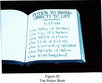
22.
The
Potion
Book
46
23.
The Toad
47
24. The
Princess
47
25.
A
Frame From
the
Dream
Sequence
54
27a.
The Original Palette
withDark
Colors
58
27b.
The
Dark
Colors Changed
to
Bright
for
Clarification
58
28a.
Constantine
Watching
the
Man
62
28b.
Constantine
withHis
Eyes
Closed
62
29a.
The Finished Characters
64
29b.
The Background
64
29c.
The
Final
Picture Composited in
the
CBG Subsystem
65
30.
The
Letters Created in
the
Curve
Drawer Subsystem
68
31
.The Letters Filled
in
the
Font
Fixer
Subsystem
68
32a.
The
Final
Title for
"Joe
Videoe"69
32b.
The
Final
Title
for "Computer
Capers"69
33.
The Final Title
for "Of Myth
and Magic"70
34a.
Lost
Scene
-The
Man
Gestures
aWand
73
34b.
Lost
Scene
-The
Man
Gestures
aHat
and aRabbit
73
35.
The Incorrect
Version
ofthe
Man
atthe
Stove
74
36.
The Next
Scene
ofthe Man
andthe
Princess
75
ACKNOWLEDGEMENTS
When I
startedthis project,
I had little idea
ofthe
amount oftime
it
wouldtake to
complete.I
countedup
the time that
I had
worked onit
andfound
that
I had
spentjust
undersome800
hours
overthe
course oftwo years,
notincluding
the time
I had
spent
writing
the
script.However,
I
could nothave
completedthis
film
alone.Many
peopledonated
their time
and experienceto
help
me createthis
film
andI
wouldlike
to thank them
allhere.
First,
I
wouldlike
to thank the
professors ofmy
thesis committee,
James Ver
Hague,
Robert Keough
andHoward
Lester,
who advised and guided methrough
this
project.They
helped
meto
structurethe
film's
story
and process and gave suggestions and encouragementto
keep
me going.Next,
I
wouldlike
to thank the
many
people ofPCI.
To Chuck
Munier,
who editedthe
film
together,
gavemany
excellent suggestionsfor
timing
andpacing
and was patient enoughto
endure along
session.Thanks
alsoto
Kristen Hartz
andEric
McMaster,
who assistedhim in
the
video control roomby keeping
the tapes
running.An
extrathanks
goesto
Kristen,
whocarefully
made all ofmy safety
masters anddubs.
And
thank
youto
Todd
Schafer,
who editedboth
soundtracks with professionalism andfun.
Many
thanks
goto
Ted
Hummel,
who allowed meto
usethe
facilities
atPCI
to
complete
my
thesis.I
also wantto
thankNina
Widger,
whotaught
mehow
to
usethe
Dubner
and gave methe
idea
to
usethe
Magritte
statuefor
the
character ofthe
sculpturefrom
a short piecethat
shehad
animated.Thank
youto
Edward I.
C.
Kinney
who was alwaysthere to
laugh
and who painted afew
ofthe
picturesI
would alsolike
to thank
Ruth Heitz
andDavid Andrus for
the
enthusiasmthey
had
creating
the
first
soundtrack andfor
finishing
it
within such a shorttime.
A
big
thank
yougoesto
John
LaBarbera,
whotook the time
from his
busy
scheduleto
createthe
second soundtrack.He
createdthe
perfect accompanimentwhich carriedthe theme
andflavor
that
I
wishedto
have for
the
film.
And
avery
specialthank
you goesto
my
husband,
Erik
Timmerman,
who gavehis
support andlove
throughout the
workofthis
film.
He
also guided methrough
the
writing
ofthe
script andhas
taught
me agreatdeal
about animation.All
ofthese
people playedvery important
rolesin
the
creation ofthis film.
Without
their
support andencouragement, this
film
would nothave
been
possible.I
wouldlike
to
givemy
humble
thanks to
them once more andhope
that
otherstudentswho plan such an endeavorin
the
future
willbe
lucky
enoughto
have
such wonderful people aroundthem
to
help
out asI did.
INTRODUCTION
My
purposein
creating
this work,
"Of
Myth
andMagic",
wasto
apply
computertechnology
to the traditional
eel animation process.During
the
course ofmy
graduate
career,
I became
employed atPCI,
alocal
video productioncompany,
as a computer animator.I began
training
onthe
Dubner
CBG-2,
athree-dimensionalanimation
system,
creating
logo
andindustrial
animationsfor different
companies.In
general, these
animations weredesigned
to
occurin
three-dimensional space,
using
the
Dubnefs
Curve
Draw
Subsytem. This Subsystem
ofthe
program allowsthe
userto
create anddefine
objects with polygons and animatethem
withtwo
methods-transforms
orbetweening. Transforms
are a set of messagesthat
instruct
the
computerhow
to
move an object or set of objects.Betweening
is
aninternal
command
that
creates a series oftransitional messagesfrom
a set oftwo
ormore recorded polygon messages.It
wasthis
method ofbetweening
that
mostclosely
resembledtraditional eel animation andthus
I
decided
to
usethe
Dubner
to
completemy
project.In
an effortto
expandthe definition
of computeranimation,
I
chose an alternate aestheticin
which two-dimensionalfigures
andflat
color were usedin
place ofthree-dimensions,
texture
mapping
or movementin
space.This
report will explainthe
different
methodsI
employedto
achievethe
effects andChapter
1
CHARACTERS
AND STORYBOARD
The first step
in
creating
this
piece wasto
writethe
story
anddesign
the
characters.I
used standarddramatic
structurein
whichthe
charactertakes action,
he
orhis
supporting
casthave
areaction,
he
has
adilemma
andthen
makes adesicion
about whatto
do
next.It
seemsthat
I
myself wentthrough
the
process ofaction-reaction-dilemma-desicion
asI
wrotethis
script.My
storyline started outfollowing
one path ofreasoning,
but
the
farther
down
the
line
ofthe script, the
less
satisfiedI
waswith whatI had
written.Thus
the
story
changedmany
times
-in
fact,
the
only
section ofthe
scriptthat
was not changedfrom
the
original storyboard wasthe
beginning,
up
to
the
pointthat the
wifeleaves
the
man.The
characters,
however,
did
not change as much.I
createdthe
manfirst,
andthen
patternedthe
wife afterhim. Both
areloosely
based
onthe
Pink Panther's
sidekickthe
Inspector.
The
dog
started out as a Scottishterrier,
but
aftertrying
to
draw him
withthe
Dubner,
I found
that
it
wouldbe difficult
to draw
along-haired
dog
and also get effective emotional reactionsfrom him.
Many
peoplehave
commentedthat
he
looks
alot
like
Snoopy,
but I
always remindthem
that
Snoopy's
ears areusually
hanging
down
andthat
his legs
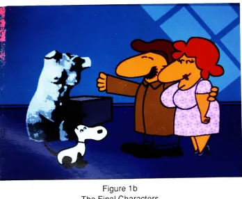
arewhite.(See Fig. 1a
andb)
The
other charactersin
this
film
were created as neededin
the
film.
They
aredescribed
later
onin
this
report.While working
onthis
film,
I
watchedmany
cartoons.Like
an apprenticepainter,
my
masters
in
the
field
wereChuck
Jones,
Tex
Avery
andHannah-Barbera from
Warner
Brothers
andMGM
cartoonfame.
I
must attribute some ofthe
actionsin
my
film
to
theirgenius.Tex
Avery,
famous for
some ofthe
most outrageoustakes
in
character animation,inspired
meto
addbug-out
eyesto
the
dog
whenhe
falls. Chuck
Jones'
Figure
1a
[image:11.532.91.443.71.364.2]The First
Drawing
Figure 1b
[image:11.532.100.448.398.684.2]potion
book
is
in "Elmer
Fuddese"1from
the
Elmer
Fudd
ofWarner Brothers
cartoons.Chapter
2
CEL
ANIMATION
AND THE COMPUTER
Cel
animationis
createdby drawing
eachframe
of a motion onto a piece ofacetate,
called a
eel,
andthen
shooting
each one ontofilm
aframe
at atime.
There
areseveral steps
up
to the
finished
product,
however.
The
animatorbegins
by
first
doing
a pencil
test
ofthe
action.After
the
preliminary
sketches arefinished,
the
animatorfilms
these
drawings
to
checkthe
flow
ofthe
movement andthen
can makeany
necessary
changes.Once
the
animatoris
satisfied withthe motion,
he
traces the
line drawings
to
the
eels.This
processis
calledinking
andis usually done
onthe
front
ofthe
cel.The
nextstep is painting
in
the
colorwhichis done
onthe
back
ofthe
eel with a special paint called cel vinyl.
The drawings
arethen
checkedfor
continuity
andthe
backgrounds
are alsodrawn
and painted.Once
the
final
eels areready, the
film
is
shotaccording
to
an exposure sheet whichtells the
camera man which orderthe
eels areto
be
placed.After
the
film
is
processed,
it is
edited andthe
soundtrackis
added.I found
using
the
Dubner CBG-2 Computer
a viable alternativeto traditional
film
animation and was able
to translate the
above process almostdirectly.
It
also afforded me some shortcuts.For
instance,
the
Dubner
playsback
an animated sequencein
realtime,
thus the time
waiting for
a penciltest
film
was eliminated.After
checking
asequence,
I
could make changes almostinstantaneously
andtry
them
again.Usually,
in
alarge
production,
many
people areinvolved
in
each process.A
key
animatordraws
the
extreme positions ofthe
action andthen
a another persondraws
the in-between frames.
With
the
computer,I drew
the
extremes andthe
Dubner
would createthe in-betweens
for
me.It
alsodrew
each ofthe pictures,
eliminating
the
needfor
the
inking
process.used
to
colorin
the
areas,
and ofcourse, there
is
nodrying
time.
Also,
in
celanimation,
several eelsmay be
usedto
create a singleframe. This
resultsin
a certain amount of"graying" ofthe
image
asthe
eels add a slight opacity.To
compensate
for
this,
the
eelsin
the
bottom layers
mustbe
painted morebrightly
than
those
atthe
top
sothat the
colors appearthe
same.With
the
Dubner"s
two
planesystem,
a character canbe
addedto the
background
with noloss
of color.Chapter
3
THE
DUBNER CBG-2
The
Dubner
CBG-2 is
avery
complex animation system.The
program consists ofthree
Subsystems: The CBG
Subsystem,
the
Font
Fixer
Subsystem
andthe
Curve
Drawer
Subsystem.
With
these
Subsystems
four
different
types
ofimages
canbe
created:text,
pictures,
points and animations.These
canbe
recorded ontodisk
as separate and specificfiles
or messages.There is
also aprogramming language for
the
Dubner
calledKeystroke
Programming
Language
whichcreates user-defined programscommonly
known
asKPLs.
Additionally,
there
areinternal
commands called<DO> commands with which messages canbe
manipulated.In
an effortto
help
the
reader understandthis system,
I
willdescribe
the
major pointshere
andthe
details
later
asthey
relateto the
specifictasks
involved in
creating
"Of
Myth
andMagic".
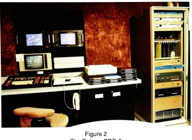
The
Dubner hardware
consists of adedicated
keyboard,
a statusmonitor, two
RGB
color
monitors,
atablet
with mouseandthe
electronics rackwhichhouses
the
microcomputer,
memory
boards,
encoders and sync pulse generator.(See Fig.
2)
The
rack alsoholds
two
disk
drives
whichtake
Iomega disks. These
disks
areflexible diskettes
or"floppies"
in
ahard
plastic case which can storeup
to
10
millionbytes
ofinformation. In
this
particularsetup, the
memory boards
hold 4
millionbytes
of random accessmemory
(RAM)
calledMeg
o'mem which canbe
used as athird
disk drive.
The
program software canbe
stored ontoany
disk
andthe
computercanbe booted
from
any
drive.
10
Figure
2
The Dubner CBG-2
Figure
3
[image:16.532.79.461.69.349.2] [image:16.532.85.464.399.650.2]The
two
RGB
monitorsdisplay
the
images
and canbe
usedto
showthe
palette of animage
in
one monitor andthe
completeimage
in
the
other.The
tablet
and mouse are usedin
the
Font
Fixer
andCurve
Draw
Subsystems
to
controlthe
cursor.THE
CBG SUBSYSTEM
This
Subsystem is
primarily
usedfor
creating
andediting
text
messages.However,
it
can alsodisplay,
manipulate and record pictures.In
this mode, the
userhas
control oftwo
display
planes,
namely
the
foreground
andbackground
planes.This
allowsthe
userto
readany
combination oftwo
pictures and/ortext
message atthe
sametime.
The
artist can also addthe
elements of one picture ortext
messageto
anotherby
afunction
key
command called <WEAVE>.Animation
messages are recorded and playedback in
realtime
from
this
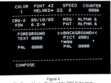
mode.Also,
withthe two
display
planeconfiguration,
an animation canbe
playedover or undera still picture.(See
Fig.
4)
COLOR
FONT
43
1
HELMED*SPEED
COUNTER
22
6
0000
CBG-2
09/10/85
VSN
6.2-N
MSG:
ALPHA
6
FNT:
ALPHA
6
FOREGROUND
TEXT
0000
PAL
0000
BACKGROUND
PICT
2001
"MAN
"PAL
0000
COMPOSE
Figure
4
[image:17.532.90.466.337.618.2]12
THE
FONT FIXER
SUBSYSTEM
This Subsystem deals
with picture manipulation andfont
creation.The
artist candraw
withthe
cursorusing
the tablet
and mouse.User-defined
single or multi coloredbrushes
canbe
created and recordedin
this
mode.A
picture can alsobe
"cleaned
up"by
moving individual
pixels orline
segments withthe
cursor.(See
Fig.
5)
COLOR
FONT
43
MAGN
COUNTER
7
HELMED*22
lX
0000
DOT
512
X=+G
LINE
283
Y=+G
SIZE=
11122
BYTES
SEG
7
=102
CLR
10=0AAC
HEIGHT=
371
TOP=
75
BOT=
445
WIDTH=
LEFT
=RGHT
=402
329
730
FIX
PICT
2001
MAN
[image:18.532.83.459.203.461.2](CLR=63)
MAG
1
POINT
CURSOR
Figure 5
The Status
Monitor
Display
ofthe
Font
Fixer
Subsystem
THE CURVE
DRAWER SUBSYSTEM
Points
and polygons are manipulatedin
this
subsystem and arethe
descriptors for
the
objectsthe
user animates.A
polygon consists oftwo
or more pointsto
describe
a
line. A
two
point polygon will create a straightline,
while athree
or more point polygon creates a curvedline. Polygons
and points canbe described in
two
orthree
dimensions.
These
polygons canbe
recordedinto
sets orgroups,
which resultsin
the
ability to
affect allthe
polygonsin
a set atthe
same time.A
set ofclosedpolygonscan
be
coloredby
using
a seedpoint, a one pointpolygon,
however,
in the
majority
ofthis work,
seed points were not used.keys
for
rotation, scaling,
duplication,
orweaving
to the
display
planeto
create a picture.The
internal
<DO>commandMBETWEEN
(multiple
betweening),
is
usedto
createthe
incremental
stepsbetween
one points message and anotherto
create a new series of points.Transforms
can alsobe
usedto
describe
the
start andstop
position of apoints messageto
create animated sequences.Though
points messages are whatthe
artist usesto
createthe
animationsequences,
they
cannotbe
recordedinto
animationfiles.
They
mustfirst be
recorded as pictures.From
a series ofbetweened
points,
aninternal
command called<EFFECT>A
is
usedto
readthe
points messagesup
and recordthem
into
picture messages.Transformed
messages canbe
recorded eitheras pointsor pictures.(See
Figure
6)
CURVE
DRAWER
6.2-N
06/10/85
2000
CURSOR
XYZ
KRGB
*
8
161
0
0000
61
520
122
0
COLOR
KRGB
NEW
POLY-->
48
G806
#
K-LIST
61
GGGQ
UIDTH
SET
2Q
1
3
1
COUNTER/STACK:
2000/
0
0
"MAN
"2GGQ
COARSE
[image:19.532.88.466.277.544.2]POINT
1
OF
7
Figure 6
The Status
Monitor
Display
ofthe
Curve
Drawer
Subsystem
<DO>
COMMANDS
These
areinternal
commandsthat
performmany
usefulfunctions
such ascopying
messages,creating
andplaying
animations,digitizing
pictures,
etc.They
areinvoked
by
typing
the
keystroke
<DO>, and thentyping
a word or code wordwith14
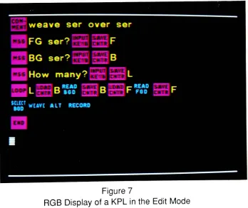
KEYSTROKE PROGRAMMING
LANGUAGE (KPL
Programs)
KPLs
are user-defined programsin
whichthe
artist candescribe
any
series ofkeystrokes
and recordthat
as a program.This language is
very
similarto
BASIC in
its
structure,
but
also allowsthe
userto
invoke
any
<DO> command orfunction
key
that the
program contains.The
mostbeneficial
use ofthis
is
in
repetitive actionssuch as read
two
series of picturesup,
weavethem together
and record themelsewhere on
the
disk. I found
that
aKPL
coulddo anything I
coulddo (except
create
the
figures)
faster
and moreefficiently
than
if I had
tried
to
do it
by
hand.
(See
Figure
7)
At
the
end ofthis report, there
is
an appendixcontaining
printouts of allthe
KPLs
[image:20.532.106.454.284.576.2]that
are usedin
this
project.Figure 7
15
Chapter
4
STARTTING
OUT
-HOW TO DRAW
THE
CHARACTERS
All
the
charactersbegan
as points messages createdwiththe
Curve
Drawer
Subsystem. A
pointis
alocation is
spacedefined in
standardCartesian
coordinates(x,
y,
andz)
and a polygonis
a collection of connected points whichdescribe
aline.
A
two
point polygon creates a straightline
and athree
or more pointpolygon makes a curve.A
group
of polygons canbe
recordedinto
a set which allowsthe
userto
affect a number of polygons at
the
sametime.
As
polygons arecreated, the
computer
keeps
track
ofthem
in
alist
of polygons.This list
is
shown onthe
status monitor and showsthe
numberofthe
polygon asit
wascreated,
its
color, width, type
and set number.
A
polygon canbe
any
colorwithinthe
palette andthis
is
shownin
the
list
by
the
palette position number.Width
refersto the
sizeofthe
line
andis
also shownby
anumber.For
example aline
width oftwo
creates avery
thin
line,
while aline
width often
draws
avery
thickline.
The
type
indicates
whetherthe
polygonis
describing
aline
or a one-point polygon called a seed point.A
seed pointdefines
the
colorof a closed area.
The
set numberofagroup
of polygonsis
user-defined anddoes
nothave
to
be
consecutiveto the
list,
but
is
limited
to
256
separatesets,
numbered
0
to 255.
After
designing
the
characters onpaper,
I
startedto
draw
them
in
points.This
seems quite simple and straightforward,but
to
usethese
messages asbeginnings for
the
extremes,
I had
to
keep
in
mindthe
constrictions ofthe
Dubner
to
makethe
between
frames.
The
<DO> command,MBETWEEN
requiresthat
a set of extremeshave
the
same number of polygons
in
the
list
andthat
each polygonhas
the
same number of points andis
the
sametype.
Color,
width and set numberareirrelevant
to this
command,
but if
they
aredifferent
from
one extremeto
anotherthey
will change at16
body
partsto
aspecificactionfor
a set ofextremes,
betweening
them
andmaking
the
pictures andthen
erasing
the
unwantedlines
later
in
the
Font
Fixer
Subsystem.
There
were otherconsiderationsto
building
the
character.It
wasimportant
to
group
the
polygons of eachbody
partinto
separate sets.By doing
this,
I
could move orrotate each
body
part as a single objectwithoutaffecting
the
rest ofthe
character.Also,
in
viewoffinal
cleanup, the
list
order and color ofthe
polygonshad
to
be
determined
in
advance ofmaking
the
extremes.Since
the
computerwilldraw
the
polygonsin
the
order ofthe
list,
I drew
the
parts ofthe
characteraccording
to
what wasclosestto the
foreground.
For
instance,
if
the
character wasfacing
screenleft,
his right
leg
had
to
be
drawn
before his left
one.Then,
asthe
character walkedfrom
right
to
left,
the
lines
ofthe
left
leg
would pass acrossthe right, thus
"cutting"the
unseenlines
ofthe
right
leg. When
these
sets oflegs
are createdin different
colors,
erasing
aline became
a simplefill
commandin
the
Font
Fixer.
When
the
userfirst
entersthe
Curve
Drawer,
he is
presented with a cursorin
the
center of
the
RGB
ordisplay
monitors and anempty
list
onthe
status monitor.The
set numberis
defaulted
to 1
,the
line
widthto
2
andthe
color numberto
whatever palette position waslast
logged
out.The
status monitor also reflectsthe x, y,
zlocation
ofthe
cursor.To begin
drawing
apolygon, the
usertypes the
function
key
<INS-POLY>.
On
the
display
monitor, this
resultsin
atwo
point polygon withthe
first
point at zerox,
zeroy,
and zeroz,
andthe
second pointten
pixelsto the
rightwhichis
selected orunderthe
cursor.The
status monitor showsthat this
is
the
first
polygon
in
the
list,
its
color,
awidthof2,
its
type
andthat
it is in
set number1
.It
alsoupdates
the
position ofthe
cursorto ten x,
zeroy
and zero z.Almost
all ofthese
parameters canbe
changedwithfunction keys.
By
typing
a numberbetween
2
and255 into
the
counterandtyping
the function
key
<RCD-MARK>
the
set number canbe
changed.Putting
a numberbetween 1
and64
in
the
counterand
typing
<SELECT-CLR-#> resultsin
the
polygonchanging
colorto that
palette position.Line
width canbe
changedby
againplacing
a numberin
the
counterand
typing
<BRUSH>.The
type
ofthe
polygon cannotbe
changedas a polygonis
eitheraline
ora seed pointdepending
onhow
it
was created.The list
number cannotbe
changed unless other polygons are created andthe
first
polygon
is
<DUPL>icatedanddeleted.
The
key
<DUPL> always createsthe twin
ofthe
selected polygon atthe
end ofthe
list
and numbersthe
copy
ofthe
set as255.
17
To
start a newset,
a new numberis
placedin
the
counter andthe
keys
<ALT> and<RCD-MARK> are used.
If
a polygonis
selected withthe cursor, that
polygonis
nowpart of
the
new set.If
no polygonis
selected, the
next polygon createdis
placedin
that
set.The
key
<DUPL>follows
avery
important
concept calledthe
Rule
ofAffected
Polygons
which controlsthe
way
sets are manipulated.This
statesthat
if
a polygonwithin a set
is
selected allthe
polygonsin
that
set are affectedby
whateverfunction
key
is
pressed.If
no polygonis
selected allthe
polygons onthe
screen are affected.For
example,
if
a polygon of a setis
selected andthe
usertypes
<DUPL>,the
entireset of polygons
is duplicated
to the
end ofthe
list.
Another
important
pair of commands whichfollow
the
Rule
ofAffected Polygons
are<ALTxDELETE-POINT> and <ALTxDELETE-POLY>. <ALTxDELETE-POINT>
deletes
the
selectedset,
while <ALTxDELETE-POLY>deletes
allthe
sets notselected.
This
canbe
avery
important
distinction
if
the
userhas
notbeen
recording
points messages regularly!
Other
commandsthat follow this
rule are<SHIFT-ROW> with an arrowkey,
<CENTR-POINTS>, <REFLECT>, <ROTATE>, <SLOW-REVL>,
<H(orizontal)-SIZE>,
V(ertical)-SIZE>,
and <BRUSH>. <SHIFT-ROW> with an arrowkey
(See
Fig.
8)
and<CENTR-POINTS> move sets of polygons around. <RELECT>turns
setsFigure
8
18
around
the
vertical ory
axis. <ROTATE> and<SLOW-REVL>turn
the
polygonscounter-clockwise and clockwise
(respectively)
aroundthe
z axis when a numberis
placed
in
the
counter.This
number mustbe
typed
as onehundred
times the
amountdesired. For
example,
if
the
user wantto
rotate a setby
90
degrees,
9000
wouldbe
typed
into
the
counter. <H-SIZE>and<V-SIZE> also usesthe
counterto
changethe
set'sproportion,
however
these
commands arelimited
to
aceiling
of200%
and aretyped
in
as such.The
key
<BRUSH> affects a setin
the
sameway
asdescribed
above
for
a single polygon.The
arrowkeys
movethe
cursor andits
selected point aroundthe
screen.There
aretwo
methodsin
whichthe
cursor can move: coarse orfine.
In
coarsemode,
onehit
on one arrowkey
resultsin moving
the
cursor128
pixels.Each
consecutivehit
in
the
same
direction
also resultsin
moving
the
cursor128
pixels.However,
reversing
the
direction
movesthe
cursor one-halfthe
distance
ofthe
previous move.Thus
onearrow right moves
the
cursor128
pixelsin
x,
one arrowleft
movesit
64
pixels, asecond arrow
left
movesit
32
and so on.In
the
fine
mode, the
cursor moves one pixel at atime,
regardless ofthe direction.
These
two
modes aretoggledby
pressing
<SPACE-BAR>.
At
this point,
I
have
only
described
how to
make atwo
pointpolygon orline.
To
createthe curves, the
function
key
<INS-POINT>is
used.This
key
inserts
a new point on a selected polygon afterthe
selected point.Thus,
if
the
cursoris
on point numberone of atwo
point polygonthe
new pointis
now numbertwo
andthe
originalpoint number
two
is
now point numberthree. Another
line
onthe
status monitortells
the
userthat the
cursoris
on pointtwo
ofthree
which refersto the
numberof pointsin
the
selected polygon and whichofthe
pointsthe
cursoris
on.By
using
the
key
<CURSR-TAB>,
the
cursormovesto the
different
points onthe
polygon.More
polygons canbe
addedby
using
the
keys
<INS-POLY>and <INS-POINT>.Each
polygonthat
is
createdis
addedto the
end ofthe
list
with one exception.If in
alist
ofpolygons, the
cursoris
selectedon a polygonin
the
middle ofthe
list,
<INS-POLY>
will resultin
the
newpolygonbeing
nextin
the
list
afterthe
selected one.Thus
if I
had
drawn
the
head
andthen the
body
ofa characterandhad
notdrawn
the
back
arm,
I
could goto the
last
polygon ofthe
head
and startinserting
polygonsto
createthe
armin
the
middle ofthe
list.
I
created profileviews ofmy
characters,beginning
withthe
man.I drew
his
head
andhat first
as set1
,then
the
body
as set2.
His
moustache was
drawn
atthe
sametime
as
his
head,
but
knowing
that
sometimeshe
wouldlook
down,
I
<ALTxRCD-MARK>ed
it
into
set3
and <DUPL>icatedit
to the
front. Then I deleted
the
original19
in
set4. For
his
back
arm,
I
selectedthe
last
polygon ofthe
head
and starteddrawing
in
set number5.
For
his
back
leg
andfoot,
I
started set number6
onthe
last
polygon of
the
back
arm.This
leg
wasduplicated
to
createthe
front
leg,
movedto
the
correct position and changedto
set number7.
However,
this
resultedin
the
front
leg
last in
the
list
andin
front
ofthe
body.
To remedy
this
I duplicated
the
body,
deleted
the
originaland changedthe
copy
back
to
set number2.
His front
arm and moustache alsohad
to
be duplicated
in
the
same manner.Thus,
I
had
createdthe
man with7
setsin
this
orderin
the
list:
first head
andhat
as set number1
,back
armas set
5,
back
leg
as set6,
front
leg
set7,
body
set2,
front
arm set4
and moustache set3.
I
created a specific paletteto
workwithto
simulate pencildrawings
and alsoto
makeit easy
onmy
eyes.I
chose alight
blue
for
the
background
anddark
greys andblack
for
the
lines.
However,
allthe
different
sets weredescribed
withdifferent
palette positions eventhough
the
color mightbe
the
same.I
alsodetermined
the
brush
width atthis
point.I
chose awidth of3 for
all medium andlong
shotsfor
the
man'sbody
and awidthof7
for
his
moustache.Using
a7
brush
eliminatedthe
needfor
many
polygonsfor his
moustache and gaveit
a coarsefeel. In
close-up
shots ofthe man,
I
changedthe
widthsto 4
and10
respectively.I
felt
that these
brush
widths werethe
proper proportionsto
the
simplicity
ofthe
way I
drew
the
character.The
wife anddog
were createdin
muchthe
same way.I
startedthe
wife'shead from
the
man'sby
selecting
the
set ofhis head
andusing
the
<ALTxDEL-POLY>command.
This left only
the
head
andfrom
that
I
addedlips
and eyelashes.Then,
I
deleted
each polygon ofthe
hat
andinserted
polygonsto
createher hair. From
that
point,
I
createdthe
wife'sbody,
againplacing
eachbody
partin
a separate set.The
dog,
ofcourse, required afresh
screen and newpolygons.I began
withhis
head
andbody,
tail,
one ear and oneleg.
His
other ear andlegs
requiredthe
use ofduplication,
newpositioning
and set and color changesto
constructhim
properly.With
these three
pointsmessages,I had
the beginnings
ofmy
main characters.The
nextstep
wasto
createthe filled-in
pictures and sothat
I
wouldhave
a reference picturein
color.Converting
these
points messagesto
picturesis
accomplishedby
a simplekeystroke
called <WEAVE> andthenrecording
the
pictureat a new message number.From
there,
I
wentto the
Font Fixer
Subsystem to
cleanup
the
unwantedlines
andfill in
the
color.20
no preferences
in moving
the
cursorin
this
Subsystem,
soI
will notdesignate
whichI
usedin
explaining
the
methods offixing
pictures.However,
the
readershouldunderstand
the
differences between using
the
mouse andusing
the keyboard.
First,
the
mouse allowsfull
freedom
of movementin
any
direction according
to
whereit is
placed on
the tablet.
The
arrowskeys
aresingularly
directional
- onehit
on an arrowkey
movesthe
cursor one pixel at atime.
If
the
key
<SHIFT-ROW>is
usedtogether withthe
right orleft
arrowkey,
the
cursorwill move20
pixelsto the
right
orleft.
If
used with
the
up
ordown
arrow, the
cursor will move1 0
pixelsup
ordown.
The
mousehas
four buttons. The
top
button
is
for
drawing
andselecting
colorsfrom
the palette, the
right andleft
buttons
arefor
zooming
in
and outrespectively,
andthe
bottom button
is
for
calling up
the
paletteto the
screen.(See
Fig.
9)
In
freehand
drawing,
pressing
down
onthe
top
mousebutton
is
preferableto
using
the
arrowkeys,
but
by
positioning
the
cursorandusing
the
key
<SEG> atwo
pixeldot
will appear onthe
screen.Or
by
using
the
key
<WEAVE>, auser-definedbrush
canbe
deposited exactly
once.Zooming
viathe
keyboard
is
accomplishedby
the
use of6
keys
named <COLORBUTTON(#)>.
These keys
zoomin
by
a power oftwo
andincrease
the
magnificationup
to 32 times
normal size.The
keyboard
has
two
buttons
to
callup
the
palette <PAL-FGD> which showsthe 64
position palette and<PAL-
BGD>
which givesthe
user6
sliderlines
to
changethe red,
green andblue,
hue,
saturation and value of a selected palette position.The
mouse callsup
the
"foreground"
or normal palette
by
one press ofthe
bottom button
andthe
"background"
or slider palette
by
two
presses.(See Fig.
10)
There
are alternate methods ofselecting
colorsbesides using
the
palette onthe
screen.
If
the
userknows
the
palette positionneeded,
he
can putthat
numberin
the
counterand press <XFER>.
This
putsthe
selected palette position onthe
cursor.Another
methodis
to
putthe
cursoronadesired
coloronthe
screen and pressthe
key
<SELECT-BGD>.Besides
freehand
painting,there
arefour
main methods ofcleaning
pictures,
all ofwhich are
keystrokes
usedin
conjunction withthe
cursor.They
are<FILL>, <ALL>,<DRAW-LINE>and <SHIFT-CHAR> with a right or
left
arrow.As
mentionedabove,
the
characters are createdto
isolate
the
parts ofthe
body
that
will notbe
seenby
drawing
the foreground
parts ofthe
body
overthem.
This
creates a segmentedline
that
canbe
<FILL>edwiththe background
colorto
eraseit.
By
using
<FILL>only
the
line
that
is
selectedby
the
cursorwillbe
erased.This is
more selectivethan
<ALL>,which erases all
lines
withthat
palette position.Of
course,
it is
notneccessary
to
usethe background
color-any
line
or area onthe
screen canbe
<FILL>edor<ALL>ed21
Figure 9
The Mouse
andTablet
Figure
10
The
"Foreground"Palette
(Top)
and"Background"
Palette
(Bottom)
<DRAW-LINE> uses
two
keystrokes
to
create atrapezoid
which will connecttwo
segments.
This is
usefulto
create a smoothline.
The
user positionsthe
cursor over one segment of color andhits
<DRAW-LINE>to
markthe
beginning
ofthe trape
zoid, then
over a secondsegment. <DRAW-LINE>the
secondtime thus
createsthe
trapezoid in
the
color ofthe
first
segment.The keystrokes
<SHIFT-CHAR> with a right orleft
arrowis
afine-tuning
method ofcleaning.
By
placing
the
cursor on a segment of color andpressing
<SHIFT-CHAR> withthe
rightarrow, the
segmentlength
increases
one pixelfor
each arrowkey
press.Conversely,
using
<SHIFT-CHAR>withthe
left
arrowdecreases
a segment of colorby
one pixel.Another
important
conceptto
consider atthis time
is
palettes and palette positions.All
pictureshave
a palette(which
canbe
recorded as a separatemessage)
and are"palette dependent". (Points
messages are not recorded withpalettes.)
By
"palette
dependent"
I
meanthat
whateverpalette positionthe
userchoosesto
draw
with, the
recorded picture will always show
that
area asbeing
drawn
withthat
position regardless
of color.To
putit
anotherway,
if
a new palette messageis
readinto
the
picturethe
position will remainthe
same evenif
the
coloris different.
For
example,let's say
I
drew
a circlein
the
middle ofthe
screen with palette position number3
whichin
palette message50
is blue
and recordedit
as apicture.If
I
readin
a new palette messageto this
picture and palette position number3
wasred, the
circlewouldthenbe
red.The
color of each palette positionis determined
or canbe
changedby
the
amount ofred,
green andblue levels
specified.The
rangefor
eachis 0
to
15,
0
being
the
least
amount and15
being
the
highest.
Thus 0
red,
0
green,
and0
blue
createsblack,
while14 red, 12
green and0 blue
creates yellow.To
changethe
values,the
user puts a numberbetween
0
and1
5
andtypes
R, G,
orB
onthe
typewriterkey
section ofthe keyboard.
Each
palette alsohas
a statuswhich canbe
opaque ortransparent.
This is
determined
by
the
numbers0
or3 respectively
andthe letter
K is
pressed.Usually,
the
only
color used as atransparent coloris
the
background
or palette position63,
but
any
position canbe
designated
astransparent.This is
usefulin
weaving
two
picturestogethersuch asthe
characterandthe
background in
the
CBG
Subsystem.
The only
other palette positionthat
is
predesignatedby
the
Dubner is
palette position number64,
whichis
the
cursor color.23
Figure
11
The
Palette
Display
in
the
CBG
Subsystem
palettes of pictures
to
be
woventogether the
same.When
two
pictures arewovenand
the
palettes arethe same, the
resulting
picture's palette remains unchanged.But,
whentwo
pictures ofdifferent
palettes arewoven, the
colors ofthe
unselected plane are addedto the
palette ofthe
selected planein
the
resulting
picture's unusedpalette positions.
For
instance,
say
I
took
my
circle picturein blue
withits
originalpalette,
placedit in
the
background
plane,
selectedthe
background
andthen
putthe
same picture and put
it in
the
foreground
plane withthe
red palette.When I
weavethe two
picturestogether,
the
palette ofthe
background
planeis
the
same with oneexception -
the
red color of
the
circle wovenfrom
the
foreground
planeis
nowin
palette position number one.
This
seemsharmless
enoughin
this example,
but if I
have
many
picturesto
weavetogether
andthey
allhave different
palettesthe
problem
increases
dramatically
and can getto the
pointthat there
are not enough positions to
hold
allthe
colors onthe
selected plane.Fortunately,
in
the
CBG
mode, the
status monitorwillflash
a statementwhentwo
pictures are woventogether
telling
the
userif
the
weave wassuccessful and whetherthe
palettes werethe
same orwere changed.
Keeping
similar palettes of picturesto
weavetogether
is
probably
mostimportant
whenit
comesto
changing
them.If
they
arethe same,
a simple commandis
usedto
change
them
-when
they
aredifferent,
the
usermay
have
to
goto
each picture24
Thus,
coloring
the
pictures ofmy
charactersis
simple enoughusing
these
methodsas
described
above.First
I
erasedthe
unwantedlines
by
<FILL>ing them
withthe
background
color.Then I
used palette position61
, ablack
color,
and <ALL>edthe
final
lines. (See
Fig. 12a
andb)
Next I
<FILL>edin
the
colors of each character.As
I
createdthe colors,
I
recorded asingle,
separate palette message and changedthat
message as
I
created new colorsfor
each character and re-recordedthe
character pictures withthe
resulting
palette.This
way I
could weavethe
pictures ofmy
characters together
andthen
changethe
colors againif
neccessary
sothat
they
wouldbe
aesthetically
compatible.The
original palettethat
I
createdin
this
stageeventually
changedin
the
final
piece,
but
by keeping
the
palettethe
samethroughout this
was a simpletask.
The
man andthe
dog
werecolored withflat
colors,
but I had different ideas
for the
wife.
From
aWarner Brothers
cartoon called"People
Are
Bunny"2,
1
remembered acharacter of a game show
host in
whichthe
charactermoved,but
the
plaid patternin
his
suit remained stationary.Since
the
wife'sdress
covered a ratherlarge
area andthus
in
one color wouldlook
sort ofplain,
I
decided
to
try
to
recreatethis technique
on
the
computer.The
wife wasalso an appropriate characterto
try
this
out on as she was notin many
scenes and sothere
wouldbe
no"overkill"
of
the
idea.
Since
the
patternhad
to
be stationary
no matter wherethe
wife was,I
knew that the
flowers
had
to
coverthe
screen.I
began
with acircularbrush that I
createdwiththe
<DO> command
CIRCLE.
This
requiresthe
userto
indicate
a radiusin
whichI
chose
1 5.
This
creates a circlein
the
centerofthe
screen.I
<FILL>edit
witha pink color and created abrush
withthe keystrokes
<BOX> and <BRUSH>. <BOX>cre atesa moveable rectangle which surroundsthe
circle(or
whateverthe
userchooses)
and canbe
adjustedby
selecting
andmoving
the
corners withthe
cursor. <BRUSH> thenturns
whatis inside
the box
into
abrush to
paintwith.Because
the
background
is
transparent andthe
circleis
opaque,the
brush
is
the
size and shapeof
the
circle.If
there
was an opaque colorsurrounding the
circle,the
brush
wouldbe
rectangular.I
made aflower
using
two
colors-one
for
the
centerand anotherfor
the
petals.
Then
I
created a newbrush
out ofthe flower.
I
began the
patternby
<WEAVE>ing the brush
acrossthe
screen,moving
the
cursor with <SHIFT-ROW>and arrow
keys. This
created a regular pattern of oneline
offlowers.
I
couldthen
make a
brush
from
this
line
to
coverthe
screen.Finally,
I
<FILL>edthe
background
with another opaque color.
(See
Fig.
13)
The
nextstep
wasto
setup
the
wife sothat the flower
pattern wouldbe in her dress
and notin
the
background.After cleaning
up
the
unwantedlines
andfilling
her
colors2 Ibid.
, pp.
269,
421. (Film: WarnerBrothers,
MerrieMelodies,
25
Figure 12a
The Characters Before
Cleaning
in Fixer
Figure 12b
26
Figure
13
The Wife's Dress
Pattern
in,
including
her
dress,
I
wentback to the
CBG
Subsytem,
placing
the
picture ofthe
wife
in
the foreground.
I
calledup
the
foreground
palette and selectedthe
back
ground color.
By
placing
anotherpalette positionin
the
counterandpressing
the
key
<SELECT-CLR-#>,
I
could reassignthe
background
areato
be
that color,
muchlike
the
<ALL>keystroke in Font Fixer. Then I
selectedthe
palette position ofthe
dress
and used
the
samekeystroke to
putthe transparent background
colorin the
area ofthe
wife'sdress.
This
series ofkeystrokes
creates a "mask".(See Fig.
14)
By
putting
the flower
pattern picturein
the
background,
the
dress
is
nowfilled
withthe
pattern.<WEAVE>ing the two
pictures togetheraddsthe
wife pictureto
the flower
picture, atwhich point
the
opaquebackground
area canbe
reassignedto
the
transparentbackground
color.(See Fig.
15)
This
new pictureis
recordedelsewhere,
saving
the
flower
pattern separately.My
final
main characteris
the
sculpture.She
is
from
aMagritte
painting
called"When
the
Time is
Up",
from
the book
"Magritte"
by
Pamela
Pritzker3.
She
wascreated
by
digitizing
orconverting
avideo signalto bit-mapped
picture.I first
photocopied
the
color pictureto increase the
contrast andto
makeit black
andwhite.The
camera
I
usedto
digitize
withis
connectedthroughthe
mainediting
suite atPCI,
where
I
could previewthe
picturethroughthe
editing
board.
The Dubner
programPamela
Pritzker,
Magritte, (New York: Leon AmielPublisher,
[nodate]),
27
Figure
14
The Wife
Created
as aMask
Figure 15
28
has
a specialdigitizing
palette which contains a range ofblack
to
white values.To
digitize,
the
<DO>commandDIGITIZE (abbreviated
DIG)
is
used.This
also asksfor
a number of otherspecificationssuch as number ofbits,
whichdetermines
the
number ofgrey levels
in
the
picture andthe
area ofthe
screento
capture as spelled outin
scanlines anddots.
There
are525
scanlinesto the
screen and1024
dots
or pixelsto
each scanline.The
scanlines are numbered1
to
525 from
top
to
bottom
andthe
dots
1
to 1 024
left
to
right.I
used4
bits
anddesignated
only
the
area ofthe
screencontaining
the
sculpture.(The
entire screen canbe
capturedusing less
bits,
however
this
resultsin fewer
grey
levels.)
I
decided
to
digitize
the
sculpturein four
different
sizes,
knowing
that
some shots would require aclose-up
and otherswould need along
shot.The
nextstep
wasto
cleanup
each picture andto
separateit
from
the
digitized
background.
I
used abrush
withthe
background
colorfor
the
majority
ofthe
image,
but her
left
side wasnearly
indistinguishable from
the
background. For
this
I
wentto
the
Curve
Drawer
to
create athick
curvedline
to form
her left
side.I
then savedthis
points message and <WEAVE>edit
to
eachdigitized
picture,
changing
the
size when neccessary.After
recording
these
newmessages,
I
separated each oneinto
a series of pictures.These
pictures containedonly
one palette position ofthe
original cleaned anddigitized
picture.By doing
this,
I
couldfill in
the
"halftone"look
into
solid areas ofthe
series of picturesthus
alsoreducing
the
number ofbytes
eachfull
picturewould use.Then
I
used<WEAVE>in the
CBG
modeto
recreatethe pictures29
Figure 16
30
Chapter
5
ANIMATION
ON THE
DUBNER
CBG-2
Since
I had
never created character animation onthe
Dubner up
untilthis
time,
I
decided
to
try
atest
run withthe
wifebefore
leaping
into
the
actualfilm. Thus
her
first
on-screen appearance wasstanding
withher
armscrossed,
frowning
andtapping
her foot. (At
the time
I
thought this
wouldbe
usedin
the
film,
but
I
neverfound
a placein
the
scriptfor
it.)
I began
withthe
original wife points messagein
the
Curve
Drawer
mode and changedthe
shape ofher
arms,
deleting
certain polygonsthat
wereher
hands,
and changedher
mouth.I
then
recordedthis
new pointsmessage at another place on
the
disk
asthe
first
extreme.As
areference, I
<WEAVE>ed
this
messageto the
background
sothat
I
wouldknow the
originalposition of
her
leg
andfoot. I
selectedthe
set ofher
leg
andfoot
and rotatedit
15
degrees
clockwise,
and movedit
to
matchthe
heel
ofher
shoeto the
originalposition.
Since
this
ofcourse movedthe
lines
ofher
leg
away
from her
body,
I
selected
the
points ofthe tops
ofher
leg
and movedthem
back
to
matchthe
wovenpicture.
This
second message ornew extreme was recordedconsecutively
afterthe
first. I
then
made more extremesfrom
these two
alternating
messages,the
last
being
the down
position ofthe
foot.
The
nextstep
wasthe
DO
commandMBETWEEN.
This
waswritten as:<DO>MBETWEEN,5040,5044,51
00,1
<ENTER>The
DO
commandMBETWEEN
asksfor
first
message(5040),
last
message(5044),
where
to
recordthe
resulting
betweens
(51
00),
and numberofbetweens (1 ). This
resulted
in
atotal
of9
points messagesincluding
5
originalsand4
newbetweens.
To
convertthese
pointsinto
aseries of pictures a command called <EFFECT>Ais
used.
This
is
a series ofkeystrokes that
readsup
each pointsmessage,
<WEAVE>s, 31
the
disk.
It is desirable