Effect of shear angles on material flow during incremental
ECAP of Al-1050 billets
Mohammad Reza Salamati
1, a, Muhammad Jawad Qarni
1, b, Saeed Tamimi
1, cand
Andrzej Rosochowski
2,1 Advanced Forming Research Centre, University of Strathclyde, 85 Inchinnan Drive, Inchinnan, Renfrewshire, PA4 9LJ, United Kingdom
2
Design, Manufacturing and Engineering Management, University of Strathclyde, James Weir Building, 75 Montrose Street, Glasgow, G1 1XJ, United Kingdom
a) Corresponding author: [email protected] b)
[email protected], c) [email protected], d) [email protected]
Abstract. Incremental equal channel angular pressing is an evolution of the traditional equal channel angular pressing method used to produce ultra-fine grain materials with significant mechanical properties compared to its course grain counterpart. In this paper we look at effects of using 90◦ and 120◦ after a first pass for a pair of 10X10X60mm billets. The forces required to produce the billets was examined and compared. Hardness maps were created to examine the change in materials mechanical properties. It was found that using the 90◦ configuration results in higher press forces nut greater uniformity of hardness distribution when compared to 120◦. The results correlated to the findings of the simulations that were carried out prior to the experimental investigation.
1
INTRODUCTION
mechanical properties is the extrusion angle. In this paper we will systematically examine the
mechanical, microstructural properties, material flow as well as finite element modelling the
differences of 90
°and 120
°Incremental equal channel angular pressingof AA-1050
2
I-ECAP PROCESS
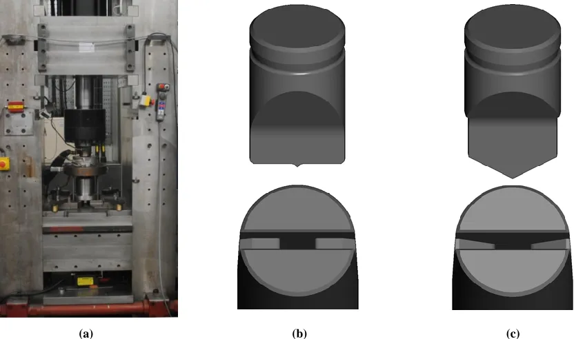
[image:2.612.151.463.327.475.2]In Incremental equal channel angular pressing (I-ECAP), the material feeding stage and the deformation stage are separated as opposed to classical ECAP [10]. The illustration of I-ECAP process shown in Figure 1 is a two billet version used in this study. A punch which follows a sine wave form (oscillates at a certain frequency and amplitude) comes cyclically in contact with the billets. The billet material is pushed into the deformation zone in increments of distance ‘a’ in Figure 1 (also known as feeding stroke) by the pusher tool, this material feeding is done when the punch is retracting. The punch then comes down and deforms the billets during the deformation stage. To facilitate material flow into the output channels the punch has a spike in the middle (not shown in the illustration). The mode of deformation is similar to that in classical ECAP i.e. simple shear, provided the feeding stroke is not large. By separating the feeding and deformation stages, reduces or eliminates friction during feeding. Thereby substantially decreasing the feeding force and enables processing of very long/infinite billets.
Figure 1: Illustration of I-ECAP process (A=Die, B=Pusher and C=Punch) [10].
The Figure 2 shows the relative motion of tools (punch and pusher) in a typical I-ECAP process. Here the punch is oscillating with an amplitude of 1.6mm at 1 Hz and feeding stoke is 0.5mm/cycle.
0.0 1.0 2.0 3.0 4.0 5.0 0.0 0.4 0.8 1.2 1.6 2.0
0 0.5 1 1.5 2 2.5 3 3.5 4 Pu
sh e r M o ve m e n t (m m ) Pu n ch M o ve m e n t (m m ) Time (sec)
Relative tool motion
Figure 2: Relative movement of punch and pusher tools during the I-ECAP process
3
EXPERIMENTAL SETUP
The I-ECAP process is carried on a customized 1000KN servo-hydraulic press which is controlled by Zwick’s Control Cube via Cubus software. The punch is attached to the press actuator and follows a sinusoidal cyclic command during processing. The material feeding is realized by a screw jack which is driven by a servo-motor. A dedicated LabVIEW application controls and synchronizes the material feeding by monitoring the punch oscillation. The application also records and captures deformation and feeding force during processing.
(a) (b) (c)
Figure 3(a): The I-ECAP experimental rig on 1000KN servo-hydraulic press. The punch and split die design for (b) ϕ=90° I-ECAP die and (c) ϕ=120° I-ECAP die.
3.1
Experiments:
[image:3.612.89.505.227.473.2]
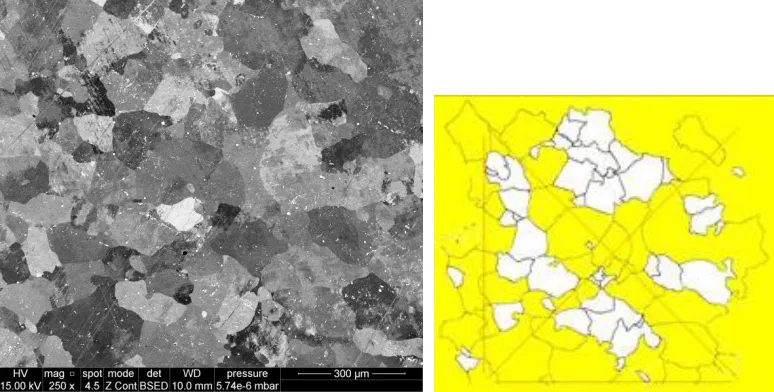
Figure 4: initial microstructure of the AA-1050 material
Experiments were performed using AA-1050 billets measuring 10x10x60mm, the billets were machined from round bars in the extrusion direction. Before the experiments could be conducted, it was necessary to perform some auxiliary steps which were related to billet preparation. These included sandblasting of billets, conversion coating the billets with Calcium Aluminate and finally applying a thin layer of Loctite 8009 (a graphite based anti-seize lubricant) from Henkel technologies. The purpose of these auxiliary steps was to reduce the friction during the processing and to avoid the sticking of billet material onto the die walls. I-ECAP process was carried out at room temperature with a cycle frequency of 30 strokes per minute (0.5 Hz), peak to peak punch amplitude of 1.6 mm and a feeding stroke of approximately 0.2 mm.
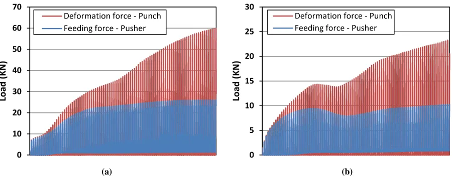
Figure 5(a) and (b) represents the shape of the billets after 50% processing with ϕ=90° and ϕ=120°. Figure 6(a) and (b) shows the recorded forces during the two experiments.
[image:4.612.85.525.478.635.2](a) (b)
(a) (b)
Figure 6: Reordered forces during I-ECAP processing for (a) ϕ=90° and (b) ϕ=120°
4
FINITE ELEMENT SIMULATION
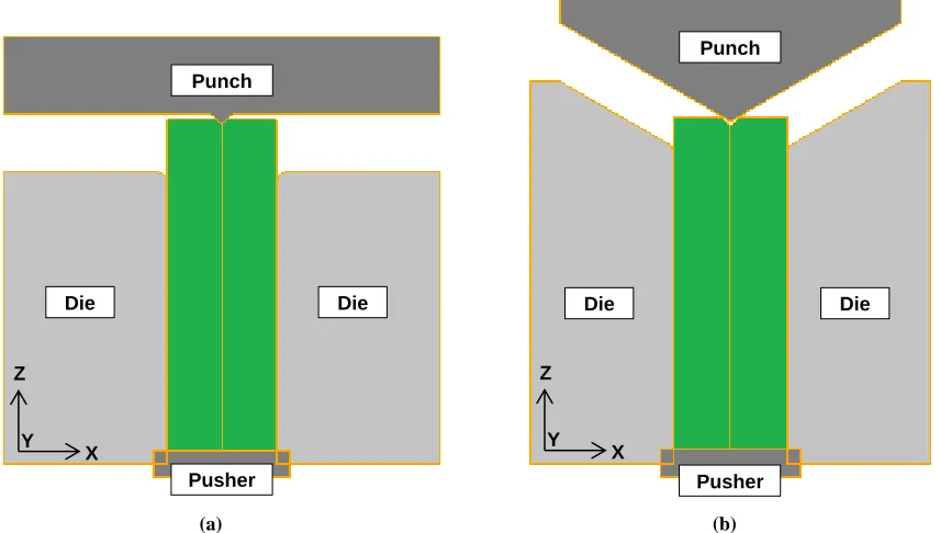
In order to analyses the behavior of the billets in the channel die, the total equivalent plastic strain, material flow and temperature rise in billets and tools during I-ECAP processing, FEM simulations have been carried out. A 3D model of I-ECAP process for two channel intersection angles (ϕ) of 90° and 120° has been developed using commercial FE code QForm. QForm was used as it had previous experience showed the capable of the software to complete simulations quickly and accurately. The material model used for these simulations can be found in the standard QForm software therefore they did not have to be found experimentally. Figure 7(a) and (b) shows the FE model for 90° and 120° channel intersection respectively, consisting of the tools and initial position of billets.
All tools (punch, die and pusher) were modelled with H13 tool steel and for the sake of simplicity are considered as rigid bodies; however with heat transfer capability. The two die elements were constrained in all degrees of freedom, however the punch and pusher were allowed to translate only along the Z-direction. The two AA-1050 billets were modelled with the built-in elastic-plastic material model in QForm which includes strain hardening behavior and strain rate effects. The billets were divided into four node tetrahedral elements. Heating of billets due to plastic deformation and friction during I-ECAP process was considered. The friction between the inner surfaces of the tools and the outside surface of the billet was modelled using Levanov law with friction factor taken as 0.3 under the graphite based lubricating conditions. However frictionless conditions were assumed between billet-billet interfaces, as the two billets are moving relative to each other. Also no interactions were considered between the tools. All simulations used automatic remeshing in billets to replace excessively distorted elements due to large strain and the occurrence of flow localizations. Volume constancy was also selected to ensure overall billets volume remains same after each remeshing step. Explicit method of integration was selected for solution. 0 10 20 30 40 50 60 70 Load ( K N )
Deformation force - Punch Feeding force - Pusher
0 5 10 15 20 25 30 Load ( K N )
[image:6.612.93.521.76.319.2]
(a) (b)
Figure 7:FE model for channel intersection angles of (a) ϕ=90° and (b) ϕ=120° I-ECAP process.
5
RESULTS
5.1
Strain distribution
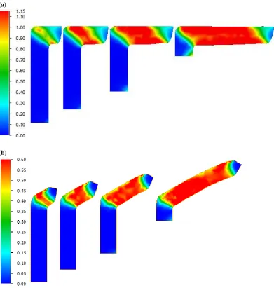
The Figure 8(a) and (b) shows the evolution of equivalent plastic strain at various stages of processing for ϕ= 90° and ϕ= 120° channel intersections respectively. As predicted the overall plastic strain is higher for the ϕ= 90° as compared to ϕ= 120°. For both cases, along the billet axis from left to right, there are three distinct deformation regions: tail, steady state and head. The steady state region of
ϕ=90° seems to show little strain in-homogeneity along both the billet axis and also along the transverse axis from top to bottom. However ϕ=120° shows strain in-homogeneity along both axes, it is also showing some bowing which was observed during actual experiments as well. This means the billets have to be straightening before they can undergo other passes. The front surfaces of the two billets in the head region are quite different from each other because of the different ϕ.
Punch
Pusher
Die Die
Punch
Pusher
Die Die
X Z
Y
X Z
(a)
[image:7.612.109.500.71.482.2](b)
Figure 8: Evolution of equivalent plastic strain distribution at 15%, 30%, 50% and 90% processed state for (a) ϕ=90° and (b) ϕ=120°.
5.2
Material flow
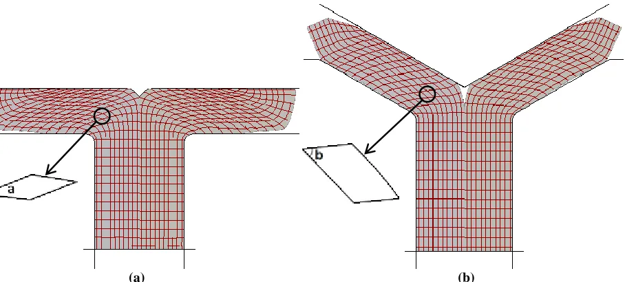
The material flow pattern and the ability of the billets to fill the die is examined by dividing the billets in a grid format using 30 lines along the billet axis and 7 lines along the transverse axis. Figure 9(a) and (b) shows the influence of ϕ on the material flow at 50% processed state for ϕ=90° and ϕ=120°. The figure also shows an enlarged single element passing through the shear zone. Shear angle ‘a’ in case of
ϕ=90° is smaller as compared to shear angle ‘b’ in case of ϕ=120°. However compared to the ϕ=90°,
(a) (b)
Figure 9: Influence of channel intersection angle ϕ on the material flow (a) ϕ=90° and (b) ϕ=120°.
5.3
Hardness measurement
A detailed hardness measurement study was undertaken to further the understanding of material change behavior during the incremental ECAP process and comparisons could be drawn between the 90° and 120° configuration. A Zwick ZHVµ micro hardness tester was used to produce the hardness maps presented in figure 6. The ZHVµ Micro Vickers hardness tester covers Vickers and Knoop hardness tests to ISO 6507, ISO 4545 and ASTM E 384 with a test load range of 0.01 to 2Kg.
The specimens were cut in half along the flow plain. The cut surface was ground and polished. A large array was configured to measure the hardness of the specimen with 1 mm intervals. The hardness of the outer 1mm of the specimens was not measured. Performing hardness measurements close to the edge of a sample will result in incorrect low readings being achieved. About 500 hardness measurements where performed for each configuration.
(a) (b)
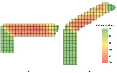
Figure 10: FE hardness map for billets during Incremental ECAP s of (a) ϕ=90° and (b) ϕ=120° I-ECAP process.
There is a distinct region separating the softer unprocessed material and the post processed material in the 90° configuration but for the 120° configuration there is a widening “V” shape transitional area separating the processed and unprocessed material. It is also noticeable that a larger section of the starting billet has remained softer in the 120 configuration and the following material exhibits less uniformity in its hardness as well as a lower peak hardness value. For both configurations, it is possible to see the headrest measurements were achieved in the center section of the billets with the outer 1mm of the material remaining 5HV softer.
5.4
Microstructure
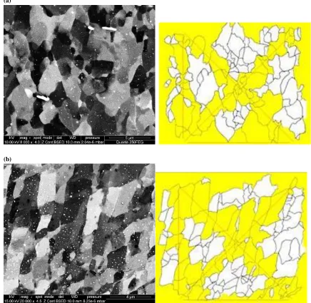
First observation: The E112 was used to measure the grain size. The mean grain size in the first pass of I ECAP of 90˚ and 120˚ are 14 and 17 micron respectively. This illustrates that smaller shear angles lead to smaller grains, even after the first pass. The figure 8 indicates that the shear deformation and consequently equivalent strain in 90˚ is higher than 120˚ which results in the grain refining at different rates. At the initial stages of I-ECAP, as a general accepted mechanism, new dislocations generated via shear deformation resulting in the sub-grains structure. By preceding the I-ECAP, misorientation of the sub-grains increase and become grain boundaries. This could explain the increase in the mean hardness in 90˚ as compared to that of 120˚. This attributed to the grain size as well as dislocation density Figure 10.
(a)
[image:10.612.67.503.77.502.2]
(b)
Figure 11: SEM examination of the microstructure of billets during (a) ϕ=90° and (b) ϕ=120° I-ECAP
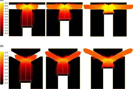
5.5
Temperature rise
(a)
[image:11.612.72.539.78.392.2](b)
Figure 12: Temperature distribution in tools and billet at 25%, 50% and 90% processed (a) 90° and (b) 120°
6
CONCLUSION
1.
First pass of I-ECAP experiments were performed on AA-1050 using the channel intersection angle (ϕ) 90° and 120°.2.
Hardness measurement suggested significant hardness increase in the deformed part compared to the un-deformed part.3.
FE simulation was performed using QForm for the first pass of I-ECAP process to predict strain distribution. The accumulated shear strain in 90 is higher than 120.4.
There is significant grain size reduction in both 90˚ and 120˚ I-ECAP.5.
After the first pass the billets that were processed using 90˚ I-ECAP configuration showed smaller and more uniform grains as compared to 120˚ I-ECAP.6.
The FEA results would also suggest the 90˚ configuration experience greater and more uniform shearstrain throughout the billet.
REFERENCES
[2] N.A. Akhmadeev, R.Z. Valiev, V.I. Kopylov, and R.R. Mulyukov, 1992: "Formation of submicro grain structure in copper and nickel by extensive shear deformation", RUSSIAN METALLURGY METAL, 2, pp. 96-101.
[3] J. Wang, Z. Horita, M. Furukawa, M. Nemoto, N.K. Tsenev, R.Z. Valiev, Y. Ma, and T.G. Langdon, 1993: "An investigation of ductility and microstructural evolution in an Al− 3% Mg alloy with submicron grain size", Journal of Materials Research, 8, pp. 2810-2818.
[4] R.Z. Valiev, 1997: "Structure and mechanical properties of ultrafine-grained metals", Materials Science and Engineering A, 234-236, pp. 59-66.
[5] I.V. Alexandrov, Y.T. Zhu, T.C. Lowe, R.K. Islamgaliev, and R.Z. Valiev, 1998: "Microstructures and properties of nanocomposites obtained through SPTS consolidation of powders", Metallurgical and Materials Transactions A, 29A, pp. 2253 - 2260.
[6] V.V. Stolyarov, Y.T. Zhu, T.C. Lowe, R.K. Islamgaliev, and R.Z. Valiev, 1999: "A two step SPD processing of ultrafine-grained titanium", NanoStructured Materials, 11, pp. 947-954.
[7] V.M. Segal, 1977: "The method of material preparation for subsequent working", Patent of the USSR No. 575892.
[8] V.M. Segal, V.I. Reznikov, A.E. Drobyshevskiy, and V.I. Kopylov, 1981: "Plastic metal working by simple shear", Russ Metally, 1, pp. 99-104.
[9] M. Furukawa, Z. Horita, and T.G. Langdon, 2002: "Factors influencing the shearing patterns in equal-channel angular pressing", Materials Science and Engineering A, 332, pp. 97-109.
![Figure 1: Illustration of I-ECAP process (A=Die, B=Pusher and C=Punch) [10].](https://thumb-us.123doks.com/thumbv2/123dok_us/1555962.108196/2.612.151.463.327.475/figure-illustration-i-ecap-process-die-pusher-punch.webp)