ISSN Online: 1947-3826 ISSN Print: 1949-2421
Network Coding Cooperation Performance
Analysis in Wireless Network over a Lossy
Channel, M Users and a Destination Scenario
Mohamed El-Hihi1, Hani Attar1, Ahmed A. A. Solyman2, Lina Stankovic3
1Department of Electronic and Electrical Engineering, Philadelphia University, Amman, Jordan 2The Military Technical Research Center, Cairo, Egypt
3Department of Electronic and Electrical Engineering, University of Strathclyde, Glasgow, UK
Abstract
Network coding (NC), introduced at the turn of the century, enables nodes in a net-work to combine data algebraically before either sending or forwarding them. Ran-dom network coding has gained popularity over the years by combining the received packet randomly before forwarding them, resulting in a complex Jordan Gaussian Elimination (JGE) decoding process. The effectiveness of random NC is through co-operation among nodes. In this paper, we propose a simple, low-complexity coop-erative protocol that exploits NC in a deterministic manner resulting in improved diversity, data rate, and less complex JGE decoding process. The proposed system is applied over a lossy wireless network. The scenario under investigation is as follows: M users must send their information to a common destination D and to exchange the information between each others, over erasure channels; typically the channels between the users and the destination are worse than the channels between users. It is possible to significantly reduce the traffic among users and destination, achieving significant bandwidth savings, by combining packets from different users in simple, deterministic ways without resorting to extensive header information before being forwarded to the destination and the M users. The key problem we try to address is how to efficiently combine the packets at each user while exploiting user cooperation and the probability of successfully recovering information from all users at D with k < 2M unique linear equations, accounting for the fact that the remaining packets will be lost in the network and there are two transmission stages. Simulation results show the behaviour for two and three transmission stages. Our results show that applying NC protocols in two or three stages decreases the traffic significantly, beside the fact that the proposed protocols enable the system to retrieve the lost packets rather than asking for ARQ, resulting in improved data flow, and less power consumption. In How to cite this paper: El-Hihi, M., Attar,
H., Solyman, A.A.A. and Stankovic, L. (2016) Network Coding Cooperation Per-formance Analysis in Wireless Network over a Lossy Channel, M Users and a Des-tination Scenario. Communications and Network, 8, 257-280.
http://dx.doi.org/10.4236/cn.2016.84023
Received: October 21, 2016 Accepted: November 27, 2016 Published: November 30, 2016
Copyright © 2016 by authors and Scientific Research Publishing Inc. This work is licensed under the Creative Commons Attribution International License (CC BY 4.0).
http://creativecommons.org/licenses/by/4.0/
fact, in some protocols the ARQ dropped from the rate 10−1 to 10−4, because of the
proposed combining algorithm that enables the nodes to generate additional unique linear equations to broadcast rather than repeating the same ones via ARQ. More-over, the number of the transmitted packets in each cooperative stage dropped from M (M − 1) to just M packets, resulting to 2 M packets instead 2 (M2 − 1) when three
stages of transmission system are used instead of one stage (two cooperative stages).
Keywords
Network Coding, Cooperative System, Erasure Channel, Diversity
1. Introduction
The design and analysis of wireless cooperative transmission protocols have gained sig-nificant recent attention to improve diversity over lossy and fading channels. The fun-damental idea of cooperation, rooted in the seminal paper of Cover and El Gamal [1], is that users within a network transmit their own information, and serve as relays to help other users’ transmissions. The achievable gains for relay channels are shown in [2]. Several energy-efficient cooperative transmission schemes have been investigated in [3] characterizing their outage behavior. In [4], a cooperative network coding (NC) system for a sensor cluster is proposed to save significant amount of the transmission power, by decreasing the Automatic Repeat Requests (ARQ) for a small number of users over the physical layer over AWGN, unlike this work where NC is proposed for a large number of users over erasure channel. Cooperation via distributed channel codes across orthogonal user channels became popular because of its simplicity, effectiveness, and practicality [5] and [6]. A survey of recent information-theoretic results and coding solutions for cooperative wireless communications is given in [7] and [8], which show how to improve the diversity. This paper contributes deterministic protocols that achieve the diversity and saves in ARQ significantly. In [9], physical layer cooperative NC is proposed and the Bit Error Rate (BER) for Decode and forward (DF) relay shows that combining a large number of packets does not affect the channel bandwidth sig-nificantly mainly over decode-and-forward channel. In [10], a comprehensive per-formance analysis of node cooperation is shown over the physical layer which shows that NC is a practical system with encouraging performance and it gives the capacity theoretical limits for some NC protocols.
alge-braic superposition of its own and its partners’ information, and decoding at the desti-nation is carried out by iterating between codewords from the two users. These schemes provide substantial coding gain over cooperative diversity techniques without NC, motivating the use of cooperation via NC. NC in [14] allows users to recombine several input packets at a relay. This is a novel paradigm which exploits the broadcast nature of wireless channels, without resorting to more traditional unicast or multicast transmissions. With NC, the relay can perform certain functions on the input data in-stead of just forwarding it. Indeed, multicast protocols based on random linear NC have been explored in lossy channels exploiting cooperation between forwarding nodes and multiple destination nodes, showing improved throughput [16], however, this work shows that even over one destination, NC is a practical system in terms of band-width savings and complexity, when using deterministic combination instead of ran-dom combinations.
In this paper, we design and analyze a complete system that enables cooperation among multiple users through the use of NC. In contrast to [7] [9] and [11] [12] [13], where the physical layer NC is investigated, we consider NC over equal-length packets implemented as a sublayer on top of the link/MAC layer, as proposed in [16] [17].
Aiming for a low complexity, practical solution suitable for the proposed scenario with small header requirements, we resort to NC over a binary field (simple XOR-ing) in a deterministic manner which deceases the Jordan Gaussian Elimination (JGE) de-coding process significantly, beside to the fact that we have no worries to repeat the same combined packet more than once when it is randomly combined resulting to more unique linear equations for the transmitted packets. We allow for packet losses in the channel and try to recover all users’ messages at a common destination and among the M users. The destination and the M users receive a set of linear combinations of us-ers’ packets in two stages, with an optional third stage in case of failure to decode some messages in the previous two stages. A user operates in cooperative mode when it for-wards a network coded packet, i.e., a linear combination of its partners’ packets. We apply both analytical and simulation tools to investigate the probability of packet error at the destination for low complexity protocols with and without binary NC. The ad-vantage of the system is; its simplicity and practicality while still maintaining perform-ance gains over non-network coding solutions.
The proposed deterministic NC protocols in this work decrease the number of the transmitted packets in the second and third stages significantly which improves the network traffic and the transmission power compared to the cooperative network without applying NC. Moreover, these protocols provide the advantage of the ability to retrieve the lost packet using JGE rather than just asking for ARQ, taking into consid-eration that the applied JGE in some scenarios is simple, because the linear equations resulted from combining the packets are made by a deterministic algorithm that gives such high diversity (independently) as shown in our work [4] where two packets de-terministically combined result in a simplified JGE process with several advantages.
for the three stages when applying NC. Section 3 presents the probability analysis for successful recovery of all users’ packets at the destination in an erasure channel. This is followed by some simulation results and analysis of system performance in Section 4. Section 5 concludes the paper.
2. System Model
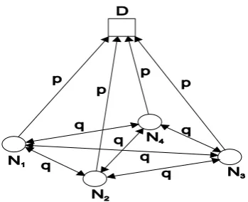
We consider a wireless network that consists of M users N1, N2, ∙∙∙, NM that transmit
messages X1, X2, ∙∙∙, XM respectively to a common destination D and to each others,
where users can hear one another over orthogonal erasure channels. We assume the channels between any two users and between the users and D can be modelled as a random packet erasure channel with q, and p probability of packet loss between the one user and another, and between the users and D respectively, as shown in Figure 1.
Communication is performed in two or three broadcasting stages of M time slots each, using TDMA. Note that the results hold for other multiple access techniques, in-cluding FDMA. User Ni generates at each stage a binary packet Xi which is broadcast
during the ith time slot. All packets are of the same length. For simplicity, we assume no
packet erasure coding. The destination informs the users with one bit broadcast back message when it successfully decodes all M messages. We assume that this feed-back message is always perfectly transmitted.
In the first transmission stage, each user Ni broadcasts its own packet Xi in one time
slot. Each of the M users receives a packet with probability 1 − q from the other M − 1 users. The destination D receives a packet from each of the M users with probability 1 − p. Stage 1 ends after M time slots.
[image:4.595.286.461.549.691.2]In the second transmission stage, we propose deterministic and non-deterministic cooperative combination strategies (protocols) with their relative merits and disadvan-tage as discussed in Subsections 2.2 to 2.4 below. Our proposed combination strategies can be seen as simple NC operation over binary field. Indeed, as in NC, a node com-putes a linear combination of incoming packets. However, in traditional NC [14], each packet is multiplied by a random coefficient, and all multiplicative coefficients are sent in the header. In our setup, all multiplicative coefficients are 1, and hence there is no need for additional header information.
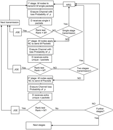
If not all packets are received after the second stage, either the system asks for ARQ or it goes for the third stage. The same mechanism is performed if there are missing packets in the third stage, so, either a further stages are required or ARQ to start the re- transmission for the missing packets.
[image:5.595.154.548.236.689.2]In this work, we propose two or three stages with optional further stages as shown in Figure 2.
The block diagram in Figure 2 shows that the transmission can finish in one, two, or three stages with sending next transmission or asking for ARQ to re-transmit what is not decoded with the option of further stages if needed, however, our proposed model is for a maximum of three stages.
In the first stage, a maximum of M single packets could be received at D, so, if fewer than M packets received, i.e., kM, the system optionally goes for the next stage. In the second stage, NC is applied to generate other M unique packets (unlike the single pack-ets), to be sent to D. Hence, D will be receiving a maximum of 2 M unique packets at the end of stage 2.
The system goes for rank check to ensure that the received unique packets at the end of stage 2, i.e., (k + l) will consists M independent linear equations (rank M) which is needed to solve JGE decoding process.
If fewer than M unique linear independent equations received; (rank M), the system goes for the third stage. In this stage, NC is applied again to obtain more M unique packets (other than what is sent by the second stage) to be transmitted to D.
At the end of this stage, D will be receiving a maximum of 3 M unique linear equa-tions, so, if the exact received unique packets at D can make the rank M received linear equations, i.e., (k + l + n) can obtain M unique independent linear equations; the sys-tem goes for the next transmission, otherwise, the syssys-tem resorts to ARQ.
In this work, we used Matlab to test the received packets rank, simply, we put the pivot 1 for the packet received at D, either single or combined, and zero if neither re-ceived nor combined.
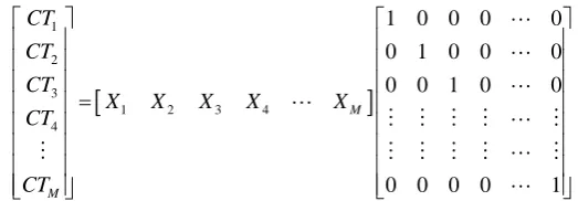
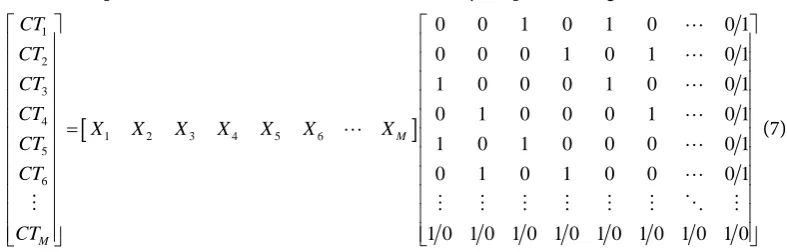
Equation (1) shows the first stage (single packet):
[
]
1 2 3
1 2 3 4
4
1 0 0 0 0 0 1 0 0 0 0 0 1 0 0
0 0 0 0 1
M
M
CT CT CT
X X X X X
CT CT = (1)
where CT1, CT2, ∙∙∙, CTM are the received packets at D and M nodes. So, if D receives the
packet from the second node; D will put in the second raw of the receiving matrix, but if the second packet is not received; D will put in the second raw.
When filling the whole matrix at D; rank test is performed over the total matrix to confirm obtaining rank M matrix or not, i.e., if the total number of the received linear equations provides M linearly independent equations.
The same for combined packets, which means if the D receives a combined packet consists of X1, X2, and X5 from the third node; D will put in the third raw of the received
matrix.
Based on above, D will be having M 2M and 3M at the end of stage one, two and three respectively.
D confirms full reception when the rank of its matrix gives rank M, i.e., collecting M unique independent linear equations from the M, 2M or 3M received packets.
[image:6.595.239.501.359.450.2]2.1. Benchmark Cooperative System
Figure 3. Three user’s benchmark cooperative system without NC, solid is for first stage and dots for cooperative benchmark second stage.
Where q, and p are the probability of packet loss between one user and another, and between the users and D respectively.
Based on Figure 3, the system transmits three packets in the first stage and nine packets in the second stage, ending up with sending 12 packets in total transmission, in general, M2 + M = M(M + 1).
Equation (1) shows the full received matrix at D and M nodes.
2.2. Stage 2 Combinations
Choice of the best combination strategy depends on the losses encountered. The main advantage of deterministic combinations over their non-deterministic counterparts is that almost no header information is needed to inform D and the M users about which packets were combined, in fact, in some combination strategies requires only 1 bit as a header. Only one combined packet (of the same size as the individual packets Xi) from
each user is sent to D and M. Thus, stage 2 requires only M transmission time slots and only M transmitted packets from the M nodes compared to M (M − 1) packets in the case of the benchmark system.
2.2.1. Stage 2 M − 1 Packet Deterministic Combination
If all M users successfully recover their M − 1 partners’ packets sent from Stage 1, the system switches to fully cooperative mode, whereby user Ni combines packets received
from all other users except its own, as given in Equation (2):
1, M
i j
j j i
C X
= ≠
=
∑
(2)q p
q
p q
p
X2
Destination D
X1
X1
X2
X2
X3
X3
X3
X1
X1,X2and X3
X1,X2and X3
X1,X2and X3
X1,X2and X3
X1,X2and X3
X1,X2and X3
N 2
N3
Equation (3) gives the received matrix at D and M nodes:
[
]
1 2 3
1 2 3 4
4
0 1 1 1 1 1 0 1 1 1 1 1 0 1 1
1 1 1 1 0
M
M
CT CT CT
X X X X X
CT CT = (3)
[image:8.595.233.492.86.181.2] [image:8.595.221.525.455.677.2]However, if any user fails to receive any one of its partners’ packets from Stage 1, only that user behaves selfishly by retransmitting only its own packet without resorting to Equation (2), moreover, the raw of that particular node in the receiving matrix will be a raw of single packet. As an example, if user two does not cooperate; the second raw of the receiving matrix will be. Thus, the network will remain in fully selfish operation only when all M users have not received one or more packets from all of their partners. In situations where such losses on such a large scale are likely to occur; we propose to combine only two packets either in deterministic or non-deterministic way as described next in Section 2.2.2 in order to avoid falling back to selfish network operation.
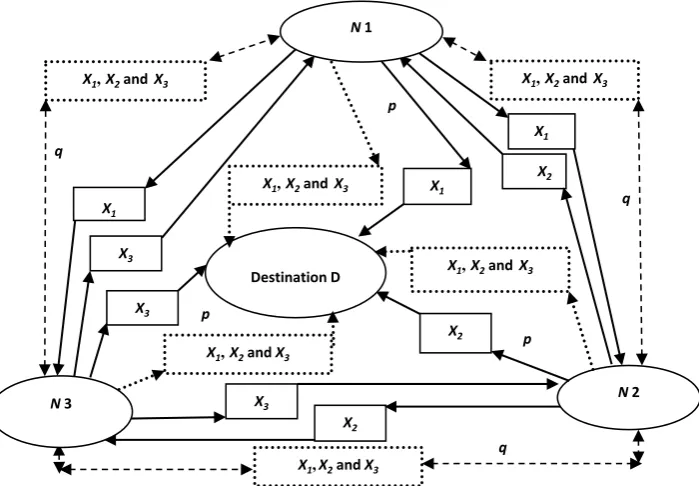
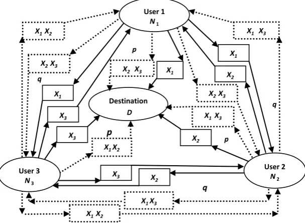
Figure 4 shows three users communicate with each other’s and with a destination D in two stages via this protocol.
Figure 4 illustrates that the users N1, N2 and N3 broadcast the packets of X1, X2 and
X3 to D through the erasure channels with loss probability of p and to each others in
with loss probability of p in the first stage. In the second stage; N1, N2 and N3 broadcast
the packets of X2 X3, X1 X3 and X1 X2 respectively to the D and each other over the same
channels as in the first stage. Accordingly, each user receives four packets, two single ones in the first stage (M − 1), and two combined packets in the second stage (M − 1),
Figure 4. Three user’s cooperative system is solid for first stage and dots are for cooperative sec-ond stage.
q X2 X3
p q q p p X2 Destination D X1 X1 X2 X2 X3 X3 X3
X2 X3
X1X3
X1 X2
X1 X3
X1 X3 X1 X2
X2 X3
X1 X2
taking into consideration that each user knows its own packet even before the broad-casting, unlike the D that does not know any packet before the first stage. In general, each user and the D will be collecting or able to obtain 2M packets in term of M single packets and M combined ones.
Only one bit header is required in this protocol to confirm whether the transmitted packet is single or combined.
As in traditional wireless NC, in order to recover all M Xi’s, a minimum of M linearly
independent equations are needed at the receiving side. Since operations are done in the binary field and all equations either reveal one unknown or contain binary sums of M − 1 unknowns, it is enough for D to receive at least M + 1 unique packets from the M users (either in selfish or cooperative mode) to obtain M linearly independent equa-tions at D, and just M unique packets at any user because the user knows its own packet. Under such case, D and the M users can recover all sources even if it has not received both packets (sent during both stages) from one user. In fact, in many cases, D can even recover all M Xis packets with M unique packets received under many cases as
will be shown in Section 3.
One of the most important advantage for this protocol that it is possible to have M linearly equations at D and M even if there is a dead channel between two users or one user and D where a user is considered dead if it cannot be heard by D or another user in both stages.
2.2.2. Stage 2 2-Packet Deterministic Combination
This protocol is ideal when any user Ni is very likely to receive from stage 1 its nearest
neighbour’s packet but unlikely to hear from all other M − 2 users.
In this protocol, the user transmits cooperatively in stage 2 by combining its own packet Xi with either Xi+1 or Xi−1. Addressing is cyclic such that if i = M, then i + 1 = 1.
Of course, if any user Ni does not receive its immediate neighbour’s packet, it
oper-ates in selfish mode transmitting only its own packet in stage 2.
Same header is needed in this protocol as the previous one, i.e., one bit to confirm whether the transmitted packet is combined or single.
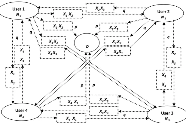
In Figure 5; each node sends one combined packet to the other three users and D+ resulting to a total of four packets at each user and D in this stage. Accordingly, 2 M unique packets at the end of this stage (M packets from the first stage, and other dif-ferent M packets from the first stage).
Taking into consideration that each user combines its own packet to the next packet only.
The receiving matrix at D is shown in Equation (4) for the case of the example in Figure 5 when all nodes cooperate:
[
]
1
2
1 2 3 4
3
4
1 1 0 0
0 1 1 0
0 0 1 1
1 0 0 1
CT
CT
X X X X
CT
CT
=
Figure 5. The cooperative second stage for M = 4 with-packet deterministic combination.
In [4], this protocol was proposed for wireless sensor network resulting to significant power saving and less traffic communication.
2.2.3. Stage 2 2-Packet Non-Deterministic Combination
This protocol is a variation of the above deterministic protocol described above, but ensures a higher likelihood of more users transmitting cooperatively in stage 2. For this strategy, any user Ni combines its own packet Xi with any one other user’s packet Xj it
has received. Simulation results show that instead of finding an Xj randomly from the
buffer of received packets from stage 1, performance is improved if Xj is chosen when
the difference i−j is minimum for all possible js. If the difference is 1, the strategy
boils down to the above strategy of Subsection 2.3.
Combination of two packets at each user in such a non-deterministic way requires a header with log2M bits, as D and the M users need to know j.
2.2.4. Stage 2 All-Received Non-Deterministic Combination
Whilst the previous two combination strategies ensure that more users operate in co-operative mode than in the strategy of Subsection 2.2, they limit the possibility of re-covery of all M users’ messages at D and the M users with as little as possible number of received packets k. We thus propose another non-deterministic combination strategy where user Ni combines its own packet with all other packets received from other users,
such that:
1 M i j
j
C X
=
=
∑
(5)where Xj is zero if Xj is not received at Ni. If all users’ packets are received by Ni, Ci is made up of the sum (in binary field) of all M users’ packets. This strategy also boils
down to the strategy of Subsection 2.2.3 if only one other packet is received by Ni.
Due to its non-deterministic nature, this strategy requires an M-bit header listing all
p q
q
q
q
p
q
q
p p
D
User 2 N2
User 3 N3
User 4 N4
User 1 N1
X2
X3
X4
X3
X1
X4
X1
X2
X1 X2
X2 X3
X4X3
X1 X2
X4X1
X2 X3
X1 X2 X2 X3
X4 X1
X4 X3
j’s combined.
After Stage 2, a total of 2M unique equations are generated by the users. A maximum of 2M unique equations is received at D and the M users, when and only when all users operate in cooperative mode. The more users operating in selfish mode, the less unique equations are obtained. Due to transmission over a lossy network, only k ≤ 2M unique packets (unique equations) will be received by D and the M users.
We go to the third stage of transmission if D or any user fails to receive at least M linearly independent equations from M or M + 1 unique packets in the M − 1 protocol, because it is impossible for D or the M users to recover all M source messages. This can happen when more than one user is not heard by D at both stages (dead users). The third stage should provide novel information to D in the form of linear combinations not previously received at D. We propose deterministic and non deterministic combi-nation strategies for stage 3 next. This stage also requires only M time slots for trans-mission. D and the M users can recover the M users’ messages when M linearly inde-pendent equations are received from all three stages. At this point, only if there are dead sources in the network will D not be able to recover all M users’ messages.
Accordingly, D received matrix will be a random mix of ones and zeroes, which makes the JGE decoding process to be complicated and consumes significant process-ing time delay. Moreover, the random combination could result to repeat the same combined packets, i.e., same ones and zeroes in D the received matrix. In such case, the replica transmitted packet will have no any unique information which means that it consumes transmission power for no any benefit. Unlike the proposed deterministic combination where the JGE decoding process is sampler [4] and there is no any possi-bility to send the same packet twice because both of the single and the combined pack-ets are all unique.
2.3. Stage 3
The third stage is needed when the system fails to collect M linearly independent equa-tions, i.e., when (k + l) unique linear equation shown in Figure 2, does not provide rank M matrix at the receiving side, which means that JGE will not be able to process the data. Moreover, the third stage solve the problem of two dead users, because it is possible to obtain the rank M matrix even with two dead users, however, a special com-bination is needed to do so, which is proposed in the sub-sections bellow.
2.3.1. Stage 3 M/2 Odd-Even Deterministic Combination
In this protocol, M/2 packets are combined at each user, resulting in a simple, determi-nistic solution. This is shown in Equation (6), where odd numbered users Ni combine
only all received packets from their odd-numbered partners excluding their own packet. The algorithm is symmetric for even-numbered users.
1, , %2 0
1, , %2 0
, %2 0 , %2 0
M
j j j i j
i M
j j j i j
X i C
X i
= ≠ ≠
= ≠ =
≠
′ =
=
∑
∑
(6)user Ni does not have all packets required to generate Ci′, then it will still be in selfish mode and send only its own packet.
Equation (7) shows the received matrix for fully cooperative stage:
[
]
1
2
3
4
1 2 3 4 5 6
5
6
0 0 1 0 1 0 0 1
0 0 0 1 0 1 0 1
1 0 0 0 1 0 0 1
0 1 0 0 0 1 0 1
1 0 1 0 0 0 0 1
0 1 0 1 0 0 0 1
1 0 1 0 1 0 1 0 1 0 1 0 1 0 1 0
M M CT CT CT CT
X X X X X X X
CT CT CT = (7)
Equation (7) shows the combined odd pivots in the receiving matrix when all com-bined packets are received either at D or M nodes. The last column is either one or zero depending on the number of node, i.e., 1 is the number of nodes are odd and zero when it is even. for 6 nodes as an example, the second raw has just two combined packets, which are X4 and X6 (even combination), hence pivots are 1 and the rest are zeroes, and
same raw 3, where the pivots are ones just at X3 and X5 (odd combination). The last raw
and last column depends on the number of users and whether it is even or odd.
[image:12.595.159.553.115.241.2] [image:12.595.193.547.563.706.2]For 1 < M < 6, each user Ni combines Xi with Xi+1, with cyclic addressing as shown in
Table 1.
2.3.2. Stage 3 2-Packet Deterministic Combination
To reduce the possible number of users in selfish mode that would occur in the above strategy, we propose another simple, deterministic odd-even strategy whereby only two packets are combined as shown in Equation (8).
2, i i i
C′ = X ⊕X+ (8)
Odd numbered users combine only the odd neighbour’s received packet Xi+2 to their
own packet. The algorithm is symmetric for even-numbered users. Again addressing is circular as in Subsection 2.3.
So, each raw in the receiving matrix will have either two pivots of ones and the rest
Table 1. Packets combination when M < 6 for two and three stages.
M = 5 M = 4 M = 3 M = 2
Users St1 St2 St3 St1 St2 St3 St1 St2 St3 St1 St2 St3 1 1 2345 345 1 234 23 1 23 123 1 2 12
2 2 1345 145 2 134 34 2 13 123 2 1 12 3 3 1245 125 3 124 14 3 12 123
4 4 1235 123 4 123 12
are zeroes in the cooperative mode, and just one pivot of number one when selfish as shown in Equation (9):
[
]
1
2
3
4
1 2 3 4 5 6
5
6
1 0 1 0 0 0 0
0 1 0 1 0 0 0
0 0 1 0 1 0 0
0 0 0 1 0 1 0
0 0 0 0 1 0 0
0 0 0 0 0 1 0
1 0 0 0 0 0 1
M M CT CT CT CT
X X X X X X X
CT CT CT = (9)
Equation (9) is for odd number of nodes, however, if the number of nodes are even, just the last raw will be changing to which is for the last even node with the first even node as the combination is a circular as in Subsection 2.3.
2.3.3. Stage 3 2-Packet Non-Deterministic Combination
This strategy is a fusion of the strategies proposed in Subsections 2.3.1 and 2.3.2 where Odd-numbered user Ni combines its own packet with any other odd-numbered Nj’s
packet, such that i−j is the minimum from all possible received Xj’s at Ni. The
scheme is symmetric for even-numbered users and boils down to the strategy of Sub-section 2.3.2 if i− =j 2. A 1 bit header is needed to inform D of j.
2.3.4. Stage 3 All-Odd-Even Received Non-Deterministic Combination
This strategy is a fusion of Subsections 2.3.1 and 2.3.2. Odd-numbered users combine all received packets from other odd-numbered users. The same goes for even-numbered users. Thus, a maximum of M/2 packets can be combined (yielding Section 2.3.1 strat-egy) and a minimum of 2 (Section 2.3.2 stratstrat-egy). A (log2M) − 1 bit header is needed.
3. Probability Analysis
In this section, we determine the overall probability of destination D being able to re-cover all M source messages given that it has received less than 2M packets during the first two stages from the M nodes. We assume that all nodes destination are within transmission range of one another.
The probability for each user is better than the probability of D, because the user knows its own packet, hence, we work out the probability of D as it is worse than users, though it is possible easily to repeat the work for each user, but we will just work for the probability of full reception for D.
After the first transmission stage, the destination will receive k packets from the M nodes, where k ≤ M different packets have been received by D at the end of stage 1 with probability of error (PER) given in Equation (10):
( ) (
)
,1 1 1
M d
P =P M = −p (10)
3.1. Benchmark Probability of Error for Stage 2
We are seeking the PER to finish the decoding after stage 2 for the benchmark protocol where each user sends its own packet twice.
So, the PER for the packet to not be received after stage 2 is p2, so, the PER to be
re-ceived is: (1 − p2), accordingly, D will finish decoding all M packet after the second
stage as shown in Equation (11):
(
2)
1 M
PER= −p (11)
3.2. PER for M − 1 Deterministic Combination Stage 2
Accordingly, the probability of receiving k packets after stage 2 is shown in Equation (12):
( )
M(
1 2)
M 2(m k) kP k p p
k M
−
= − ⋅ ⋅
(12)
And PSymb is shown in (13):
( )
Symb
k
P P k
M
= ⋅ (13)
In this stage, each user will either switch to fully cooperative behaviour (if it has re-ceived and decoded all the M − 1 partners’ packets) with probability
(
)
( 1)1 M
c
P = −p − ,
or the user will remain in selfish mode with probability PS = −
(
1 Pc)
.After the second stage of transmission is finished, we are interested in the probability
,2 d
P that the decoding at the destination is successfully completed. This is given by
Equation (14):
( ) ( )
,2 ,2 1
0 M
d d
k
P P k P k
=
=
∑
(14)where Pd,2
( )
k is the conditional probability that the decoding will be successful after the second stage, given that the destination received k user packets in the first stage from all users.As we have M different packets, D must receive M linearly independent equations, i.e., any number of different equations that gives rank M receiving matrix at D. Ac-cordingly, D evaluates the received rank matrix, and in the case of having M rank, D informs the M users that all packets have been recovered; otherwise, more transmis-sion’s stage is needed or D will declare that more uses are dead.
As the combination in the second stage is deterministic, the M users generates maximum of 2M unique packets. However, D needs to receive just M + 1 unique packet to guarantee obtaining rank M receiving matrix.
In the case when D cannot hear from two users (the case of two dead users), D can-not receive M linear independent packets, which means that the received matrix’s rank is less than M, though M + 1 unique linear equations have been received.
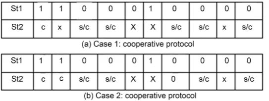
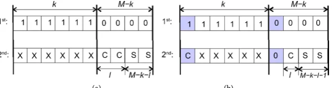
Figure 6.M + 1 received packets at D. (a) and (b) are the solvable cases.
Where 1 denotes successfully received packet, 0 denotes lost packet, S/C denotes a packet received in either selfish or cooperative mode, and X denotes any possibility of either received or lost packet. However, D can guarantee to obtain the M rank receiving matrix when D receives the packet in cooperative mode for one user received in stage 1 as shown in Figure 1. This means that any M + 1 different packets give M linearly in-dependent equations, taking into consideration that we are seeking the definite prob-ability to obtain the rank M received matrix at D.
Equation (15) and Equation (16) show the PER for these cases.
The decoding will successfully finish if for all (M + 1) − k time slots in which trans-mission failed in the first time slot, the transtrans-mission is successful in the second time slot. The decoding will succeed irrespective of the behaviour (selfish or cooperative as long M rank linear equations received) of users in these M − k time slots, this is illus-trated in Figure 6(a),
(
)
(
(
(
)
)
)
1 1 1 1 1
k M k
case
PER = −p − ⋅ − − −p Pc (15)
Moreover, even if one of M − k users’ packets is not received in the first time slots, remains not received in the second time slots (dead case), the decoding will succeed if, in the remaining k time slots, the destination receives at least two user’s packets in co-operative mode.
An example of this case is illustrated in Figure 6(b) where Cr denotes to a packet
re-ceived in cooperative mode.
So, for case 2 PEP is given by Equation (16):
(
) (
)
1(
(
)
)
(
)
(
(
)
)
12 1 1 1 1 1 1
k k
M k case
PER = M−k p −p − − ⋅ − −p Pc −k −p Pc⋅ − −p Pc − (16)
With these two successful decoding outcomes, we obtain Equation (17):
( )
(
(
(
)
)
)
(
)
(
) (
)
(
)
(
)
(
)
1
,2 1
1
1 1 1 1 1 1
1 1
k M k M k
d k
k p Pc
P k p Pc p M k p p
p Pc
− − −
−
−
= − − − − + − − −
− −
(17)
where Pc is the probability to receive the packet in cooperative mode.
Though M + 1 unique equations always give M linear independent equations, which is enough to recover the M received packets, D can obtain the M linear independent equations from just M packets as shown in the following cases:
sce-narios that lead to successful decoding of all M nodes after stage 2, illustrated in Figure 7.
Before describing them, we note the following important fact; Let l ≤ M to be the number of combined equations received from l different nodes. We focus on the l × l subsystem containing these l combined equations, restricted only on the corresponding l nodes. This subsystem has full rank l if l%2 = 0, i.e., the even number of combined packets for subsystem of l has full rank received matrix, hence, its solvability.
Figure 7(a) illustrates the first solvable case when, after receiving k ≥ 0 selfish equa-tions in the first stage, in the second stage, each of the remaining M − k nodes succeed in transmitting either selfish or combined equation. If out of these M − k equations, l ≤ M − k are combined equations, the system is solvable, otherwise, it is not solvable. Note that whatever is received by k nodes already received in the first stage is irrelevant. The probability of the first solvable case is given in Equation (18):
( )1
( )
,20 %2 0
.
M k
d C S
M k
M k
P k P Pι ι
ι ι ι − − ≤ ≤ − = − =
∑
(18)Figure 7(b) illustrates the second solvable case when, after receiving k ≥ 1 selfish equations in the first stage, in the second stage, M − k − 1 out of the remaining M − k nodes succeed in transmitting either selfish or combined equation, and one node is not successful for the second time. Then, if during the second stage at least one combined equation is received from any of the k nodes already received in the first stage, the sys-tem is solvable. Note that in this case, the number l ≤ M − k − 1 of combined equations among the M − k − 1 combined schemes for different M’s equations received by nodes unsuccessful in the first stage but successful in the second stage, is irrelevant. The probability that the second solvable case occurs is shown in Equation (19):
( )
( )
(
(
(
)
)
)
(
)(
)
12 1
,2
0
1
1 1 1 1
M k
k M k
d C C S
t
M k
P k P P M k P P Pι ι
ι − − − − − = − − = − − − ⋅ − − ⋅
∑
(19)If two or more nodes do not succeed in transmitting any equation to the destination node during both stages, the system can be given in Equation (20):
( )
( )1( )
( )2( )
,2 ,2 ,2
d d d
P k =P k +P k (20)
Replacing Equation (20) in Equation (14), the probability Pd,2 is obtained.
If D fails to receive at least M linearly independent equations from M users, a third
[image:16.595.208.544.583.672.2](a) (b)
transmission stage is considered whereby novel information in the form of linear com-binations not previously received at D is transmitted as proposed in Sections 2.3.1 to 2.3.4.
[image:17.595.249.498.546.689.2]Then, probability Pd + 3 of successful decoding after three stages can be calculated similarly as in Equation (20), as D will declare the ability to decode all M packets when receiving rank M matrix. Probabilistic analysis for other schemes is possible but in some cases tedious. We leave the complete probabilistic analysis for our future work, and explore the performances of all the schemes, including the three stage transmis-sion, using simulations in the following section.
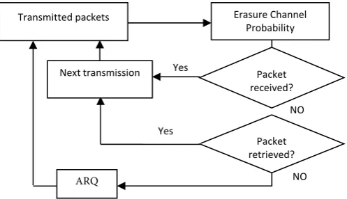
Figure 8 shows the block diagram for the system design with NC over the erasure channel for two stages transmitting.
The block diagram shows that the receiver tends to check the packets reception from the first stage transmission, and if not received, it tends to retrieve the packet by the helps of the combined packets received by the second cooperative stage.
If any packet neither received nor retrieved, is then asked to be retransmitted unlike the scenario where NC is not applied which is retransmitting the packet in the case when it is not received only.
4. Results
This section presents the results and observations of our simulation experiments to de-termine how our proposed cooperative protocols based on NC reduce the probability that all N1+ N2+, ∙∙∙ + NM are not successfully decoded, Pe+ at D node ,with no extra
transmitted packets compared to the benchmark protocol, where q, and p are the probability of packet loss in the channels between one user and another, and between the users and D respectively.
The benchmark protocol (Figure 3) shows that M (M + 1) packets are needed com-pared to 2M when applying NC (Figure 3) for two stages system. Accordingly, our aim is to find how NC helps improving PER with no extra transmitted packets compared to benchmark protocol, beside to the benefits to compare all protocols with each others to understand their behaviour, taking into consideration the saving in transmitted packets (2M or 3M) and in the need for ARQ, which justifies the saving in data rate.
Figure 8. System set-up Block diagram with NC. The Figure justifies the improvement in PEP.
NO
NO Yes
Next transmission
ARQ
Packet retrieved? Yes
Packet received?
Transmitted packets Erasure Channel
It is important to confirm that these results have been obtained by Matlab when ap-plying the M rank indicator for full reception, i.e., to confirm whether the system man-aged to decode the information or ARQ is needed.
Figure 9 shows the behaviour of Pe when applying all the proposed protocols as
compared to the benchmark protocol for transmission in two stages. Results show how deterministic protocols are as competitive to the non-deterministic (random) with re-spect to Pe, but with the advantage of the deterministic combining such as 1 bit header
in the M − 1 protocol, the easier Gaussian elimination decoding as the received packets are either single or combined in a deterministic way and the ability to solve one dead channel in the case of M − 1 protocol. Moreover, we can see that the M − 1 determinis-tic combination outperforms all received combined at high error rate i.e., p = 0.25, and this shows how the deterministic combination is stable and can stand dropping large number of packets, taking into consideration that the channel is allowed to drop M − 1 packets in the way.
Combinations of 2-packets provide acceptable Pe improvement though their
perfor-mance is considerably weaker than both the M − 1 deterministic and all received com-bined protocols. In addition, the deterministic degree 2 next neighbour deterministic protocol is as competitive as the closest neighbour protocol, but does not require head-er fields, this is justified by using the same head-erasure probabilities for all distances. The Pe
behaviour of the M − 1 deterministic combination protocol for different number M of nodes is presented in Figure 10, showing that the M − 1 deterministic protocol is as competitive to the non-deterministic all-received combined protocol even for a large number of nodes. It also shows that increasing the number of nodes M deteriorates performance of both cooperative protocols and the benchmark non-cooperative proto-cols.
Moreover, Figure 10 shows the worsening performance of the M − 1 deterministic combined protocol when increasing the erasure probability q between nodes. The
Figure 10.Pe for 2-stage M − 1 deterministic and all received combined schemes for different M’s.
threshold behaviour of q is notable, where the performance at low values of p is signifi-cantly improved if q ≤ 0.3, and otherwise, deteriorate signifisignifi-cantly.
Figure 11 shows the M − 1 deterministic combination when changing the erasure probability between the M users. The clear threshold in Figure 8 is justified by obtain-ing the sufficient number of unique linear equations, i.e., when more than 30% losses packets, it is becoming harder to obtain the unique M + 1 linear equations.
In the final part of results, we focus on the deterministic three stages to give more details through the results as the theoretical analysis is tedious.
Figure 12 shows the performance of the deterministic system that transmits odd-even protocol Section 2.3.1 in the third stage, instead of repeating fully combined (M − 1) protocol in Section 2.2.1.
As noted in Sections 2.2.1, fully combined equations are used to solve the problem of one dead channel. The motivation for odd-even equations is that reception of these equations enables recovery of any two users that were unable to send data to the desti-nation (two dead channels). However, the destidesti-nation can make use of only one odd and even equation; the rest of possibly received equations of this type are useless. Note that the number of users that will send odd-even cooperative equation in the third stage depends on q.
This explains the PER results in Figure 11 where there is an optimum value of q (q = 0.2) for which the system performs better than for fully cooperative case q = 0.
Figure 13 illustrates the interval of q values, q = [0.3, 0.6] for which it is better to send odd-even (Equation (2)) than to repeat the fully combined (Equation (3)) in the third stage.
Figure 11.Pefor 3-stage M− 1 deterministic combination example, M = 10 and different q’s.
Figure 12.Peperformance of deterministic combined/odd-even cooperative scheme for three transmission stages.
odd-even or fully combined equation with appropriate optimal probabilistic decision that depends on q have a potential to further improve the overall PER performance.
Moreover, Figure 13 shows the performance gained by the third transmission stage, when the channel between users are good (0.03), indeed, the Pe improved from 5.3 e−3
to 4e−5 at p = 0.1, the cost of this good improvement is sending M extra packets.
When comparing three stages strategies, we notice that three stages deterministic out performs the three stages random combination clearly after the threshold p = 0.3, which showed in Figure 6 and Figure 9, though just one bit header file is required. We can notice that using random combination when p is more than 0.35 is slightly better than our proposed deterministic combination, but it requires M header file.
[image:20.595.213.535.286.483.2]Figure 13. Peperformance of deterministic combined/odd-even cooperative scheme for three transmission stages.
Finally, Figure 14 shows that repeating odd-even in the third stage results to worsen performance than the random combination, so, it is suggested not to repeat odd-even combination in the third stage.
Based on above Figures, we can see clearly the gain obtained in Pe when applying NC
compared with the Benchmark when NC is not applied, taking into consideration that our protocols use just the simple XOR combination which is simple and easy to be re-trieved at D using XOR again in the same manner. Moreover, the different protocols give different performance, so, the proper protocol depends on the application it is aimed for.
5. Conclusions
Motivated by recent results from [11] [12] [13] on the diversity and coding gains ob-tained by using NC in cooperation protocols, we propose several practical transmission protocols for a typical data gathering scenario that boasts simplicity and low-complexity while still maintaining performance gains over non-NC solution.
We designed simple practical protocols that apply the deterministic NC at M nodes to improve the system data rate and to reduce the traffic significantly, through combi-nation among the M nodes and with D.
Applying NC in a cooperative manner allowed the system to recover all the data at the M nodes and D even in the case of one dead channel in the two stages, and two dead channels in the three stages transmission. Moreover, the ARQ improved signifi-cantly, in fact, the ARQ reduced from 10−1 to 10−4 for the whole system with better data
rate and simplicity of decoding the data with Jordan Gaussian Elimination.
Figure 14. Comparison of three and two stages for M = 10 at good erasure probability (q = 0.03).
cooperative protocols based on deterministic NC. Simulation results demonstrate a perfect match with the analytic results and also show the performance benefits of using deterministic compared with non deterministic protocols. Moreover, we show that de-terministic combination is as competitive as the non dede-terministic but without the overhead of headers the advantage of using simple Gaussian Elimination decoding process. We also prove that it is sufficient for D to recover M + 1 unique packets from any three stages to completely recover all M users’ messages when using M − 1 proto-col.
Our future work is to show the good benefit in term of data security when applying the proposed protocols, besides extending the system for more than one destination.
Moreover, applying the proposed protocol over the physical layer is under investiga-tion and will be published soon with Partial Unit Memory Turbo Code (PUMTC) as the forward error correction tool, and to show what is the impact of the accumulative noise when combining the packets together in Amplify-and-Forward (AF) relay and with Decode-Re-encode-and-Forward (DF) relay with the channel capacity limits in both scenarios.
Finally, applying the proposed protocols over real applications is among our future plan as well, such as applying these protocols over mobile networks, and wireless sensor networks
Acknowledgements
Philadelphia University deserves my acknowledgements for the good atmosphere they maintain for their researchers and for the financial support for this research.
work. They always add good values for my research work.
References
[1] Cover, T.M and Gamal, A.E. (1979) Capacity Theorems for the Relay Channel. IEEE
Transactions on Information Theory, 25, 572-584.
https://doi.org/10.1109/TIT.1979.1056084
[2] Laneman, J.N. and Wornell, G.W. (2000) Energy-Efficient Antenna Sharing and Relaying for Wireless Networks. IEEE Wireless Networking and Communications Conference, Chi-cago, 23-28 September 2000. https://doi.org/10.1109/wcnc.2000.904590
[3] Laneman, J.N., Tse, D.N.C. and Wornell, G.W. (2004) Cooperative Diversity in Wireless Networks: Efficient Protocols and Outage Behavior. IEEE Transactions on Information
Theory, 50, 3062-3080. https://doi.org/10.1109/TIT.2004.838089
[4] Attar, H., Stankovic, L. and Stankovic, V. (2012) Cooperative Network-Coding System for Wireless Sensor Networks. IET Communications, 6, 344-352.
https://doi.org/10.1049/iet-com.2011.0143
[5] Stefanov, A. and Erkip, E. (2004) Cooperative Coding for Wireless Networks. IEEE
Trans-actions on Communications, 52,1470-1476. https://doi.org/10.1109/TCOMM.2004.833070
[6] Hunter, T.E. and Nosratinia, A. (2006) Diversity through Coded Cooperation. IEEE
Trans-actions on Wireless Communications, 5, 283-289.
https://doi.org/10.1109/TWC.2006.1611050
[7] Stankovic, V., Xiong, Z. and Host-Madsen, A. (2006) Cooperative Diversity for Wireless Ad Hoc Networks: Capacity Bounds and Code Designs. IEEE Signal Processing Magazine, 23, 37-49. https://doi.org/10.1109/MSP.2006.1708411
[8] Liew, S.C., Zhang, S. and Lu, L. (2013) Physical-Layer Network Coding: Tutorial, Survey, and Beyond. Physical Communication, 6, 4-42.
https://doi.org/10.1016/j.phycom.2012.05.002
[9] Attar, H., Stankovic, L. and Stankovic, V. (2009) Physical-Layer NC based on PUM Turbo Codes. IEEE Mosharaka International Conference on Communications, Signals and Cod-ing, Amman, February 2009.
[10] Attar, H., Vukobratovic, D., Stankovic, L. and Stankovic, V. (2011) Performance Analysis of Node Cooperation with NC in Wireless Sensor Networks. 4th IEEE International
Confer-ence on New Technologies, Mobility and Security, Paris, 7-10 February 2011.
[11] Azarian, K., El Gamal, H. and Schniter, P. (2005) On the Achievable Diversity-Multiplexing Tradeoff in Half-Duplex Cooperative Channel. IEEE Transactions on Information Theory, 51, 4152-4172. https://doi.org/10.1109/TIT.2005.858920
[12] Xiao, L., Fuja, T.E., Kliewer, J. and Costello Jr., D.J. (2007) A Network Coding Approach to Cooperative Diversity. IEEE Transactions on Information Theory, 53,3714-3723.
https://doi.org/10.1109/TIT.2007.904990
[13] Yu, M., Li, J. and Blum, R.S. (2007) User Cooperation through Network Coding. IEEE
In-ternational Conference in Communications, Glasgow, 24-28 June 2007.
https://doi.org/10.1109/icc.2007.669
[14] Li, S.-Y.R., Yeung, R.W. and Cai, N. (2003) Linear Network Coding. IEEE Transactions on
Information Theory, 49, 371-381. https://doi.org/10.1109/TIT.2002.807285
[15] Koetter, R. and Medard, M. (2003) An Algebraic Approach to Network Coding. IEEE/ACM
Transactions on Networking, 11, 782-795. https://doi.org/10.1109/TNET.2003.818197
Coding Using Opportunistic Feeding and Routing. IEEE Transactions on Parallel and
Dis-tributed Systems, 25, 3264-3273. https://doi.org/10.1109/TPDS.2013.2297105
[17] Katti, S., Rahul, H., Hu, W., Katabi, D., Medard, M. and Crowcroft, J. (2006) XORs in the Air: Practical Wireless Network Coding. IEEE/ACM Transactions on Networking, 16, 497- 510. https://doi.org/10.1109/TNET.2008.923722
Submit or recommend next manuscript to SCIRP and we will provide best service for you:
Accepting pre-submission inquiries through Email, Facebook, LinkedIn, Twitter, etc. A wide selection of journals (inclusive of 9 subjects, more than 200 journals)
Providing 24-hour high-quality service User-friendly online submission system Fair and swift peer-review system
Efficient typesetting and proofreading procedure
Display of the result of downloads and visits, as well as the number of cited articles Maximum dissemination of your research work
Submit your manuscript at: http://papersubmission.scirp.org/