International Journal of Innovative Technology and Exploring Engineering (IJITEE)
ISSN: 2278-3075, Volume-9 Issue-1, November 2019
Abstract: In the evolving industrial revolution, automation plays an important role. Automating the machineries we use can reduce the human efforts on operating it. The basic process involved in paper manufacturing includes wood preparation, pulping, chemical recovery, bleaching and paper making to convert wood to final product. In paper industries, moisture content is the most important parameter in the drying section. Controlling the moisture content of the paper is important for maintaining the paper quality and for the economical usage of energy. The paper drying involves heat transfer, evaporation and moisture removal processes where steam pressure, cylinder surface temperature, hood balance and condensate removal plays important roles in determining drying capacity and final product quality. To attain the required quality and flexibility 5-7% moisture is necessary. Hence the heat in the dryer removes the moisture content of the paper leaving it dry. The dryers will be operated continuously to perform this process which leads to high power consumption. In order to reduce the power consumed the dryers will be operated only for some instance corresponding to the moisture level of the paper in the drying unit. Hence the overall efficiency of the plant will be increased, which leads to reduced power consumption and increased productivity.
Keywords: Measurement, Dankness, Control, Moisture.
I. INTRODUCTION
Steam flow in drying unit is one of the most important parameter in paper industry. The hot air from the dryer causes the water content in the paper to evaporate, leaving it dry. At the end of the operation the paper will contain only 5-7% moisture which is necessary for the paper to maintain its quality and flexibility.
1.1 EXISTING METHOD
The existing techniques involves reduction in the lengthy of the drying unit which consist of improved water removal in the press section equipped with heated press rolls, multi-tier arrangement of drying cylinders, hot air impingement-assisted drying, superheated steam drying, gas-fired drying cylinders and condebelt drying cylinders. Another method uses infrared source to detect the moisture content which involves high initial cost. Also this involve only simulation model. The simulation predicted that this would lead to a production increase of almost 20 rn/min, just over 2%. This technique would not be feasible on the basis of increased drying rate alone but would need to be co-justified by other factors.
The disadvantages of the existing methods are
• High capital investment
• Real time data has not been arrived, which makes it difficult for further development
• High power consumption
• Real time feasibility is not possible
1.2 PROPOSED METHOD
Wet paper has to be dried to obtain the end product. Proximity sensor detects the presence of the paper in the dryer and sends the signal to the controller. The Amplifier circuits are designed and it is used to amplify the voltage signal to drive the stepper motor. The moisture sensor senses the moisture content of the paper and the
solenoid valves are opened to spray the steam on the dryer to make the paper dry. It helps to reduced the power consumption and the dryers works only when the proximity sensor detects the wet paper.
II. HARDWAREDESCRIPTION
Dankness control consists of the several components in order to do a particular task to obtain an expected output
The overall working of the project can be seen in the block diagram and in schematic representation. The main components for controlling the dankness are Arduino controller UNO, Motor driver, two channeled relay module, DC gear motor, humidity sensor, proximity sensor and dryers etc.,
2.1 ARDUINO UNO
[image:1.595.346.504.491.592.2]Arduino UNO is a microcontroller board based on 8-bit ATmega328P microcontroller. Along with ATmega328P, it consists other components such as crystal oscillator, serial communication, voltage regulator, etc. to support the microcontroller. Arduino Uno has 14 digital input/output pins (out of which 6 can be used as PWM outputs), 6 analog input pins, a USB connection, A power barrel jack, an ICSP header and a reset button. The supply, which will be provided to arduino, can be done in two different ways, either by USB connection or by using an external power supply. AC-DC adaptor and battery will come under the category of external power supply. To use battery, connection is given to Vin and GND pins on the board. To use adaptor, connection of a 2.1mm centre positive plug in to the board’s power jack. The most suitable range is 7-12V. If the input voltage is less than 7V, the on-board regulator can’t produce proper regulated 5V and the board will become unstable. If the input voltage is more than 12V it will cause the voltage regulator to be overheated and may result in damaging the board. The Arduino UNO can be seen in Figure 1.
Figure 1 Arduino UNO
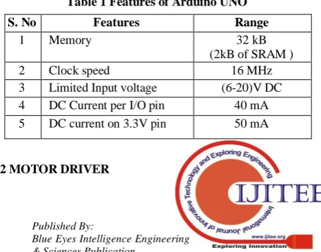
This Arduino board acts as a heart of the project and it is used to control the relays and sensors. Arduino UNO has some unique features compared with other micro controllers as shown in Table 1.
Table 1 Features of Arduino UNO
S. No Features Range
1 Memory 32 kB
(2kB of SRAM )
2 Clock speed 16 MHz
3 Limited Input voltage (6-20)V DC 4 DC Current per I/O pin 40 mA 5 DC current on 3.3V pin 50 mA
2.2 MOTOR DRIVER
[image:1.595.312.545.650.832.2]L293D is a motor driver controller circuit which is generally used to quadruple high current half-H drivers. The L293D is designed to provide bidirectional drive currents of up to 1 A at voltages from 4.5 V to 36 V and also provides bidirectional drive currents of up to 600-mA at voltages from 4.5 V to 36 V. L293D is fabricated exclusively to drive inductive loads such as relays, solenoids, DC and bipolar stepping motors, as well as other high-current/high-voltage loads in positive supply applications. The L293D circuit is shown in Figure 2.
Figure 2 L293D Driver Circuit
Each output is a complete totem-pole drive circuit, with a Darlington transistor sink and a pseudo Darlington source. Drivers are enabled in pairs, with drivers 1 and 2 enabled by 1, 2. EN and drivers 3 and 4 enabled by 3, 4 EN to rotate the rollers in a consecutive manner.
2.3 TRANSFORMER
A Step-down transformer is shown in Figure 3. It is a static device which converts high primary voltage into low secondary voltage. In a step-down transformer, the primary winding of a coil has more turns than the secondary winding. It works on the principle of Faraday’s law of electromagnetic induction.
Figure 3 Single Phase Transformer
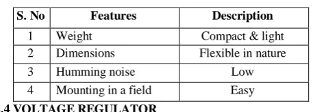
[image:2.595.113.227.150.239.2]The features of the step-down transformer are shown in Table 2. It is used to provide the supply for controllers and sensors.
Table 2 Features of Transformer
S. No Features Description
1 Weight Compact & light 2 Dimensions Flexible in nature
3 Humming noise Low
4 Mounting in a field Easy
2.4 VOLTAGE REGULATOR
Two voltage regulator (7805 & 7812) IC’s are used to provide supply to the controllers. 7805 is used to provide the input voltage (+5V DC) from the transformer to the Arduino UNO. 7812 provides +12V DC to the motor driver controller from the transformer. The voltage regulator is shown in Figure 3.
Figure 3 Voltage Regulator Board
[image:2.595.306.549.300.400.2]Both the IC’s can be soldered in a single board. The voltage regulator performs only in DC not in AC. There is a rectifier and filter circuits to convert the 12V AC to 12V DC. The voltage regulator is a system designed to automatically maintain a constant voltage level. A voltage regulator may use a simple feed-forward design or may include negative feedback. It may use electromechanical mechanism or electronic components used to convert from one domain to another. Since the board has two IC’s, the features will vary which is listed in the Table 4.
Table 4 Features of Voltage Regulator
S. No Features 7805 7812
1 Input voltage (7-25) V DC (14.6-35) V DC
2 Operating current 5 mA 8 mA
3 Junction Temperature
125°C (max) 125°C (max)
4 Output voltage 5V DC 12V DC
2.5 TWO-CHANNELED RELAY MODULE
[image:2.595.111.225.409.497.2]Relays are switches that are used to open or close electromechanically or electronically after the trigger from the UNO. Generally, the relay is in NC manner. When the S1/S2 pin is connected along with Vcc and GND, it becomes NO. The supply voltage is +5V DC and the output from the relay which is used here is 230V AC. The 2-channel relay module is shown in Figure 5.
Figure 5 Two channeled Relay Module
2.6 DC GEAR MOTOR
[image:2.595.344.503.466.558.2]A DC gear motor is a rotating electrical device that converts direct current, of electrical energy, into mechanical energy. The unique characteristics of DC gear motor are as shown in Table 5.
Table 5 Features of DC gear motor
S.No Features Range
1 Input supply +12V DC 2 Gear Ratio 28:1 3 Rotating speed 10 rpm
4 Connection type Shunt / series / compound
5 Motor constants Kv & Km
[image:2.595.51.280.570.652.2]International Journal of Innovative Technology and Exploring Engineering (IJITEE)
ISSN: 2278-3075, Volume-9 Issue-1, November 2019
magnetic field that creates rotary motion as DC voltage is applied to its terminal. Inside the motor is an iron shaft, wrapped in a coil of wire. This shaft contains two fixed, North and South, magnets on both sides which cause both a repulsive and attractive force, in turn, producing torque. DC gear motor used to rotate the rollers to move the paper after proximity sensing.
2.7 HUMIDITY SENSOR
The DHT11 humidity sensor is a basic, ultra low-cost digital temperature and humidity sensor. It uses a capacitive humidity sensor and a thermistor to measure the water content present inside the paper through non-contact type. The sensor has three pins which can be controlled to an 8-bit µC (Arduino UNO). A separate library file must be included in a µC in order to perform the specified task. This sensor includes a resistive element and a sensor for wet NTC temperature measuring devices. It has excellent quality, fast response, anti-interference ability and high performance.
[image:3.595.303.549.244.368.2]The following Table 3.6 shows the features of a DHT-11 moisture measuring sensor.
Table 6 Features of DHT-11
S.No Features Range
1 Operating voltage (3.3V – 5V) DC 2 Operating current 60 µA – 0.3 mA 3 Withstand temperature (0-50)°C
4 Humidity (20-90)%
5 Interface Digital
2.8 PROXIMITY SENSOR
[image:3.595.62.283.273.366.2]Proximity, which is used here, is photoelectric type. This sensor is used to detect the presence of paper in the roller. When the sensor energizes, it emits the light beam and when it hits the target, it returns to the receiver which is placed inside the sensor. When the sensor senses, the data sends to the controller, and the controller sends the pulse to the DC gear motors to rotate the rollers. The photoelectric proximity sensor is shown in Figure 3.10. When emitted light is interrupted or reflected by the sensing object, it changes the amount of light that arrives at the Receiver.
Figure 6 Photoelectric type proximity sensor
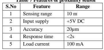
[image:3.595.82.253.489.595.2] [image:3.595.326.525.579.680.2]The Receiver detects this change and converts it to an electrical output. The light source for the majority of Photoelectric Sensors is infrared or visible light (generally red, or green/blue for identifying colors). The features can be shown in Table 7.
Table 7 Features of proximity sensor
S.No Feature Range
1 Sensing range 10 m 2 Input supply +5V DC
3 Accuracy 20µm 4 Response time <2s 5 Load current 100 mA
2.9 DRYERS
Dryers, also known as a blow dryer, are an electrical device used to dry the paper according to the moisture content present in it. It
uses an electric fan to blow air across a heating coil; as the air passes through the dryer it heats up. When the warm air reaches wet paper it helps evaporate the water. It works on the principle that when air is heated, the relative humidity gets decreased. The lower the relative humidity, the more easily water evaporates. Therefore, hot air will dry the moisture faster, since the water in the paper will evaporate more quickly.
2.10 ASSEMBLY BOX
The assembly socket is used for providing power source to the dryers when the relays are actuated according to the sensors output. The assembly box consists of 2 pin socket along with the indicators. There is a reason for undergoing this kind of setup. The setup works automatically and it there is no need for the manual switches.
2.11 ROLLER SETUP
The setup, which is employed is here, is welded in an unique manner in order to maintain the nominal level of moisture in the water. The setup is shown in Figure 7.
Figure 7 Roller setup
The rollers actuates only when the proximity senses the paper. When it senses, the signal is sent to the controller and from the controller the pulse will be generated to initialize the rollers.
III. TECHNICALDESCRIPTION
The dankness control consists of two units which performs the operation and controls the process.
• Control Unit • Roller Unit
3.1CONTROL UNIT
Control unit, also called as brain of the process, works according to the programming language which is coded. The language used is Embedded C which differs from the normal C language. Each component in this unit is placed for a specific purpose. The block diagram of the control unit is shown in Figure 8.
Figure 8Block Diagram of Control Unit
[image:3.595.70.252.659.747.2]component involved in the unit can be seen in the Table 8.
Table 8 Functions involved in control unit
Name Function
Arduino UNO
Acts as the brain of the unit. It controls the relays in the control unit and motors and sensors in the roller unit Transformer Converts 230V AC to 12V AC for the supply of motor
driver controller and the arduino controller. Regulator
circuit
Consists of 2 ICs (7805 & 7812) along with the electrolytic capacitors are placed for filtering. 7805 converts 12V AC to 5V DC which will be given to the supply to UNO and 7812 converts 12V AC to 12V DC which is the supply for motor driver to rotate the motor. L293D Motor-driver controller used to control the motor in a
distinct direction
after it receives the pulse from the controller Relays Solid state electromagnetic type in which it supplies the
230V AC to the
socket box when it receives impulse from the controller. The supply is given to the COM from the switch.
Socket box Box is placed to provide supply for hair dryers Assembly
box
Gateway for providing 230V AC to the control unit board
IV. WORKING OF OVERALL PROCESS
[image:4.595.303.533.448.556.2]Initially, the power supply is given to the transformer and the transformer converts 230V AC to 12V AC. Then, the 12V AC is given to the regulator circuit which consists of 2 IC’s which converts the 12V AC to 12V DC from 7812 and 5V DC to 7805 parallel. The supply for the arduino can be done in two aspects: one through the USB and the other is with the VIN pin in the regulator board to the UNO. The output of the 7805 is connected with UNO and the 7812 is connected with the motor driver. Motor driver is fixed in order to control the motors which are placed in the roller unit either in forward or in reverse directions. The arduino connects the relay and also the sensors in the roller unit. The relay passes the 230V AC to the socket box only if the relay receives the pulse from the UNO. The dryers are plugged in the socket box and spray the hot air after receiving the supply automatically. The control unit board which is used here is shown in Figure 9.
Figure 9 Control unit Board
4.1 ROLLER UNIT
Roller unit acts as the heart of the project. The reason for calling the roller unit as a heart is because it rotates according to the command of the brain. Like the control unit, the components used here is also for the specific function and a specific task.
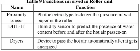
The roller unit consists of sensors and motors which is used to rotate the rollers in the roller unit. There is an automation role used for controlling the moisture content in the paper. Each component has the unique features which can be listed in the following Table 9.
Table 9 Functions involved in Roller unit
Name Function
Proximity sensor
Photoelectric type to detect the presence of wet paper in the roller
DHT-11 Humidity sensor to predict the presence of water content before and after the hot air passes-on
Dryers Device to pass the hot air automatically after it gets energized
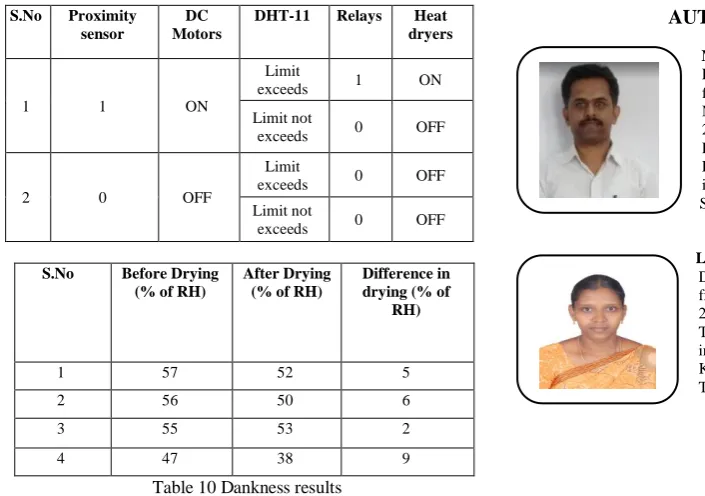
DC Motors Acts as a roller after connected with the PVC pipe in the roller unit. It rotates when proximity senses The working of the roller unit can be viewed in the following sub-section of this chapter. Proximity sensor detects the presence of paper in the roller. When it detects, the arduino sends an impulse to L293D where it rotates the motor. Then DHT-11 senses the water content in the paper, so that dryers are actuated by the relays in the control unit to pass the hot air on the wet paper to make it dry. Again DHT-11 senses the water content to differentiate the moisture level. Finally the paper will be collected and headed to cutting and packing unit.
4.2 WORKING OF THE PROJECT
When the supply is given, the transformer steps down the voltage and supplies it to the regulator circuit. It is then given to the arduino and the motor driver controller. The supply of sensors is given from the arduino and engaged to perform the sensing process. When proximity senses the presence of the paper, it sends the value to the arduino and from the arduino an impulse gets generated. The generated impulse is sent to the motor driver and the DC motors gets rolled out. The DHT-11 sensor senses the moisture content present in the paper. When the reading reaches beyond the set point, the arduino sends an impulse to the relay and the relay becomes NC and provides the supply to the socket box. The dryer which is connected in the socket releases hot air to the wet paper. The water content present in the paper gets evaporated by passing through the two heat dryers. After passing out, again DHT- 11 is used to check the moisture and to show the difference after passing the dryer. The processed paper is connected in a separate roller and taken to the next unit.
V. RESULTANDDISCUSSION
The pulp has been formed by processing the raw materials and the paper will be produced from the pulp by undergoing pressing operation. Different papers with different quality, GSM, and flexibility will be obtained. The final hardware prototype is shown in the Figure 10.
Figure 10 Final Hardware Unit
[image:4.595.59.278.460.571.2] [image:4.595.56.282.693.775.2]International Journal of Innovative Technology and Exploring Engineering (IJITEE)
ISSN: 2278-3075, Volume-9 Issue-1, November 2019
S.No Proximity sensor
DC Motors
DHT-11 Relays Heat
dryers
1 1 ON
Limit
exceeds 1 ON
Limit not
exceeds 0 OFF
2 0 OFF
Limit
exceeds 0 OFF
Limit not
exceeds 0 OFF
S.No Before Drying
(% of RH)
After Drying (% of RH)
Difference in drying (% of
RH)
1 57 52 5
2 56 50 6
3 55 53 2
[image:5.595.44.397.48.296.2]4 47 38 9
Table 10 Dankness results
VI. CONCLUSION
Thus the dankness control of paper using dryers is used to optimize the power consumption. Compared to the existing method if offers reduced usage of power, investment cost, fuel consumption, and also increases the overall efficiency of the plant. By this method, the manufacturers can produce the paper with required quality and flexibility. However, the current system is based upon sensors in which the worker needs to stick with the system. In future, if Industry 4.0 was revolutionized successfully, then this system can also be implemented using IoT so that it can be operated from anywhere. By switching ON the dryers for a particular instance of time, the wastage of the power can be optimized.
REFERENCES
1. Perry Y.Li, Shri Ramaswamy and Petar Bjegovic (2003), “Pre-emptitive control of moisture content in Paper manufacturing using surrogate measurements”, Transactions of the Institute of Measurement and Control, Vol.25, No.1, pp.36-56.
2. Lakshmi.M, Raja.C (2012), “Intelligent identification of moisture control of drying process in paper machine”, CiiT International Journal of Automation and Autonomous System, Vol.20, No.5, pp-81-94.
3. H.W.Gebele (1962), “Moisture Measurements in Industry”, IRE Transactions on Industrial Electronics, Vol.-9, No.1, pp.7-10. 4. S.Kalaivani, C.Harris Naveena (2013), “Paper Moisture Based
Steam Usage Reduction in Paper Plant”, International Journal of Application or Innovation in Engineering & Management (IJAIEM), Vol.2, No.11, pp. 383.
5. Jobien Laurijssen , Frans J. De Gram, Ernst Worrell, Andre Faaij (2010), “Optimizing the energy efficiency of conventional multi-cylinder dryers in the paper industry”, Centre of Competence Paper and Board, Vol.6, No.7, pp.1231-1236
6. Jobien Laurijssen, Andre Faaij, Ernst Worrell (2013), “Benchmarking energy use in the paper industry: a benchmarking study on process unit level”, Springer, Vol.6 No.1 pp-43-63 7. https://www.convergencetraining.com/paper-machine-alternative-dr
ying-systems.html
AUTHORS
PROFILE
Mahesh N completed hisBachelor’s Degree in Electronics and Instrumentation Engineering from Bharathiar University in 2003 and Master’s Degree in Applied Electronics during 2007. He is currently working as Assistant Professor at Kongu Engineering College, Perundurai, Tamil Nadu. His area of interests include Embedded Systems and Wireless Sensor Networks