Abstract: The industrial drive is normally using three-phase induction motor, since they need high speed –torque performance operations. The speed control is normally in open loop. However, these open loop drives are not giving good performance. The closed controller is playing a role in the design of any closed loop system. PI controller is the best conventional controller. The fuzzy and neural based controller is better than PI controller for many applications. Hence, in this chapter, a fuzzy logic based closed loop speed control of motor is investigated. In addition to speed control, the current controls are pre-requisite for providing the smooth speed-torque characteristics. In this paper a 3Ф five-level DC to DC converter five-level CHB-MLI fed variable speed motor with proportional integral and fuzzy logic controller are modeled and investigated using MATLAB/Simulink. The analysis is made with various modes of operation of motor drive. The FPGA SPARTAN-3 controller based experimental setup is realized and tested for the proposed HCC and FLC speed controller. The experimental results are conforming simulation results and prove the FLC performance against speed and HCC.
Keywords: MLI; PI; FLC; CHB; FPGS; HCC
I. INTRODUCTION
This work deals with the design and control strategies of closed loop converter tied three-phase CHB-MLI fed inductor motor drive with hysteresis current and fuzzy logic speed controllers. The MATLAB-Simulink models are created and microcontroller-based experiment is performed and results are presented.
II. OPEN LOOP BUCK-BOOST CONVERTER FED THREE-PHASE CHB-MLI FED INDUCTION
MOTOR SPEED CONTROL
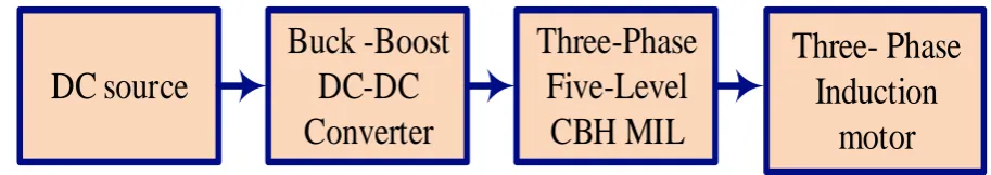
The block diagram of open loop buck-boost converter fed 3Ф CHB-MLI fed Induction motor drive is shown in figure 1, which consists of two switch buck-boost DC – DC converter and three-phase five-level CHB-MLI. Here the conventional seven-level CHB-MLI is used to control the induction motor.
DC source
Buck -Boost
DC-DC
Converter
Three-Phase
Five-Level
CBH MIL
Three- Phase
Induction
[image:1.595.71.528.412.493.2]motor
Fig. 1 Open loop buck-boost converter fed three-phase CHB-MLI fed Induction motor The figure 2 shows buck-boost DC – DC converter fed
three-phase five-level CHB-MLI topology. The voltage output of the proposed MLI is synthesized with the help of six H-bridge inverter circuit. Each H-bridge contains one autonomous voltage source “VDC” and four power switches with SA1, SA2, SA3, SA4.
Revised Manuscript Received on March 08, 2019.
Chinnapettai Ramalingam Balamurugan, Department of Electrical and Electronics Engineering, Karpagam College of Engineering, Myleripalayam Village, Othakkalmandapam, Coimbatore, 641032, India
P.Abinaya, Department of Electrical and Electronics Engineering,
Karpagam College of Engineering, Myleripalayam Village,
Othakkalmandapam, Coimbatore, 641032, India
S.Aravind, Department of Electrical and Electronics Engineering,
Karpagam College of Engineering, Myleripalayam Village,
Othakkalmandapam, Coimbatore, 641032, India
K.Gowsith, Department of Electrical and Electronics Engineering,
Karpagam College of Engineering, Myleripalayam Village,
Othakkalmandapam, Coimbatore, 641032, India
D.M.Tamilselvan, Department of Electrical and Electronics Engineering, Karpagam College of Engineering, Myleripalayam Village, Othakkalmandapam, Coimbatore, 641032, India
The voltage sources of the H-bridge are an identical voltage VDC and its can be solar, fuel cells or batteries. The total number of switch used in the proposed CBH-MLI is 24 (6×4=24). Each H-bridge output voltage can be achieved to either “-VDC”, “0” or “+VDC”.
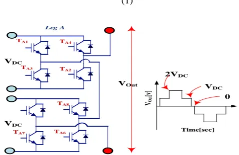
The Figure 3 illustrates a five-level CBH-MLI leg-A topology design and output voltage waveform. Here, two four switch H-bridge with identical voltage, VDC are present and produces three-level in half cycle voltage form as 0, VDC, 2VDC. Table 1 shows the five-level CBH-MLI leg-A switching positions and relationships for output voltages. Considering figure 3 with five-level CBH-MLI leg-A topology (two bridges) and Table 1, the switch in each H-bridge is “ON” and “OFF” and cascading them to synthesis output voltage.
Comprehensive Analysis and Response of Closed
Loop CBBCTPNLI System with PI and FLC
Comprehensive Analysis and Response of Closed Loop CBBCTPNLI System with PI and FLC
TA2
TA1
TA3
TA4
A
VDC
3-Phase Induction Motor
L
SB-A1
+
-SB-A2 D1
D2
C1 C0
VDC
-+
TA8
TA7 TA6
Buck-Boost DC to DC Converter-A1
L
SB-A1
+
-SB-A2 D1
D2
C1 C0
VDC
-+
TB2
TB1
TB3
TB4 VDC
TB8
TB7 TB6
TC2
TC1
TC3
TC4 VDC
5 Level CBH
Leg A
TC8
TC7 TC6
B
C
Leg A Leg B Leg C
Buck-Boost DC to DC Converter-A2
BBC-B1
BBC-C1
BBC-B2 BBC-C2
[image:2.595.131.468.57.266.2]TB5 TC5
Fig. 2 Buck-boost DC – DC converter fed three-phase five-level CHB-MLI topology
Applying voltage balancing Kirchhoff‟s law in five-level CBH-MLI leg-A topology. The generalized equation for the MLI is composed of “n” bridges and derived as,
(1)
VOut
TA2
TA1
TA3
TA4
TA8
TA7 TA6
Leg A
VDC
VDC
VOut
[v
] VDC
2VDC
0
[image:2.595.177.417.327.483.2]Time[sec]
Fig. 3 The five-level CBH-MLI leg-A topology and the waveform (output voltage) Table. 1 Five-level CBH-MLI leg-A switching positions and relationships for output voltages
Upper H-Bridge Cell Lower H-Bridge Cell Vout
SA1 SA2 SA3 SA4 SA5 SA6 SA7 SA8
X X X X 2VDC
X X X X VDC
X X X X X VDC
X X X X VDC
X X X X VDC
X X X X 0
X X X X 0
X X X X 0
X X X X 0
X X X X 0
X X X X 0
X X X X -VDC
X X X X -VDC
X X X X -VDC
X X X -VDC
[image:2.595.45.554.530.758.2]III. THREE-PHASE BUCK-BOOST CONVERTER FED MLI FED INDUCTION MOTOR CURRENT CONTROL HYSTERESIS CURRENT CONTROL The figure 4 shows the circuit diagram of CBBMLI fed IM drive systems with HCC. The figure 5 shows the buck-boost DC – DC converter fed three-phase five-level CHB-MLI topology with HCC.
DC source
Buck -Boost
DC-DC
Converter
Three-Phase
Five-Level
CBH MIL
HCC
I
ref
I
error
I
act
Three- Phase
Induction
[image:3.595.115.489.144.316.2]motor
Fig. 4 Proposed CBBMLI fed IM drive Systems with HCC
HCC Iref
*IDC
GSB1 GSB2
HCC IDC
Iref *IDC
TA2
TA1
TA3
TA4
A B C
VDC
Induction Motor 3 Level CBH
L
SB-A1
+
-SB-A2
D1
D2
C1 C0
VDC
-+
Leg A Leg B
Leg C
Buck-Boost DC to DC Converter for Leg B Buck-Boost DC to DC Converter for Leg C
Buck-Boost DC to DC Converter for Leg A
HCC
IDC
Iref *IDC
IDC
GSB1 GSB2
HCC Iref
*IDC
L
SB-A1
+
-SB-A2
D1
D2
C1 C0
VDC
-+ Buck-Boost DC to DC Converter for Leg A
TA5 TA8
TA7 TA6
[image:3.595.141.458.344.561.2]IDC
Fig. 5 Buck-boost DC – DC converter fed three-phase five-level CHB-MLI topology with HCC
L
SB1
+
- S
B2
D1
D2
C1 C0
VDC
-+
GSB1
HCC
IDC
Iref
PI fs
+
-+
-IDC*
[image:3.595.183.418.598.719.2]Comprehensive Analysis and Response of Closed Loop CBBCTPNLI System with PI and FLC
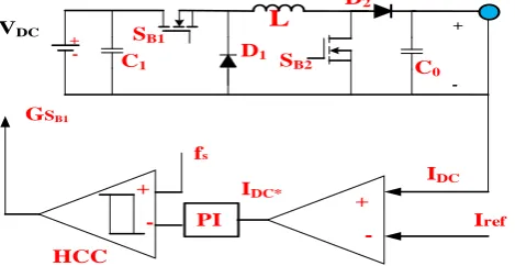
The converter output current measured (IDC) and compared with reference current (Iref) provides current error (IDC*). In HCC, the peak currents of the inductor (ΔiLmin and ΔiLmax) are compared with reference current in the desired converter power switch. The reposed HCC does not need any external oscillator or saw-tooth wave generator and it has the capability to offer a quick response to a transient event. The figure 5.6 shows the proposed buck-boost DC – DC converter HCC. The HCC control one switch connected series with inductor for the smooth input current, which ensures the flat speed- torque characteristics of motor drive. The fixed frequency fixed hysteresis band is used in this study. After driving the current hysteresis bands, they are compared with switching frequency to find the duty cycle of the converter. A simple PI controller is used to maintain the hysteresis band current reference. The PI controller used in this controller validates the error signals to deliver a reference current for HCC. Therefore, the HCC method can be viewed as a sliding mode control system.
The hysteretic comparator implements the control law i.e.
(2)
where, S is the sliding surface, which is defined as the variance between the two comparator inputs (1,0).
(3)
IV. CLOSED LOOP THREE PHASE BUCK-BOOST CONVERTER FED MLI FED INDUCTION MOTOR CURRENT CONTROL WITH PI AND HYSTERESIS
CURRENT CONTROL
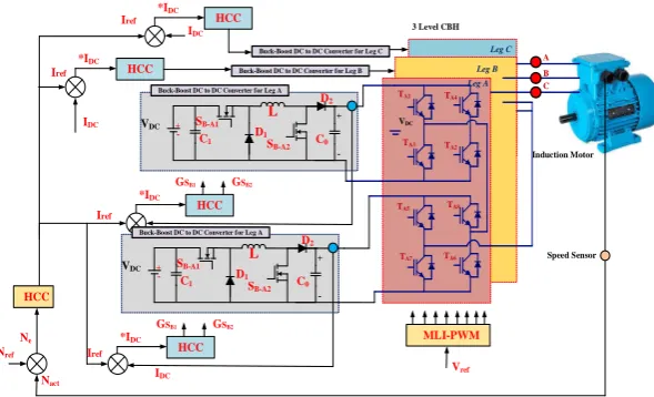
The block diagram of closed loop 3Ф buck-boost converter fed MLI fed IM current control with PI and hysteresis current control is shown in figure 7, which consists of two switch buck-boost DC to DC converter and three-phase five-level CHB-MLI. Here the two switch DC to DC converter connected to seven-level CHB-MLI H-bridge and the converter duty cycle is derived through HCC. The inner loop is a current controller and output loop acts as a speed loop. In speed loop the compared motor actual speed and reference speed is calculating reference current to inner HCC. The HCC give the gain to DC to DC duty cycle to control the inverter DC-link voltage and current.
DC source
Buck -Boost DC-DC Converter
3-Phase 7-Level Inverter
Induction Motor
HCC
I
refI
actPI
N
refN
errorN
Pulse generator Duty Cycle
I
act* [image:4.595.52.460.297.491.2]V
refFig. 7 Block diagram of closed loop 3Ф buck-boost converter fed MLI fed IM current control with PI and hysteresis current control
HCC Iref
*IDC
GSB1 GSB2 HCC
IDC *IDC
Nref Ne
Nact
MLI-PWM TA2
TA1
TA3
TA4
A B C
VDC
Induction Motor 3 Level CBH
L
SB-A1
+
-SB-A2 D1
D2
C1 C0
VDC
-+
Leg A Leg B
Leg C
Buck-Boost DC to DC Converter for Leg B Buck-Boost DC to DC Converter for Leg C Buck-Boost DC to DC Converter for Leg A
Speed Sensor
HCC Iref
*IDC
GSB1 GSB2 HCC Iref
*IDC
L
SB-A1
+
-SB-A2 D1
D2
C1 C0
VDC
-+
Buck-Boost DC to DC Converter for Leg A
TA5 TA8
TA7 TA6
Vref Iref
IDC
IDC
HCC
[image:4.595.150.445.528.707.2]The Figure 8 display the closed loop three-phase buck-boost converter fed MLI fed Induction motor current control with PI and hysteresis current control. The Figure 9 shows
the pulse width generation of CHB- MLI. The first H-bridge pulse width generation for phase-1,2 and 3 are given in below figure.
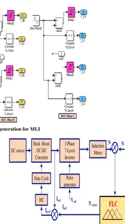
HCC- Phase A HCC- Phase B
[image:5.595.296.547.91.540.2]HCC- Phase C
Fig. 9 Gate pulse generation for MLI
Reference Signal
Gating pulse of T-A1
Gating pulse of T-A2
One Cycle
Fig. 10 Pulse width modulation of single leg CHB- MLI The figure 10 shows the pulse width modulation of single leg CBH- MLI. Here, the reference signal is compared with carrier signal and generating continuous pulses.
V. CLOSED LOOP THREE PHASE BUCK-BOOST
CONVERTER FED MLI FED INDUCTION MOTOR CURRENT CONTROL WITH FLC AND
HYSTERESIS CURRENT CONTROL
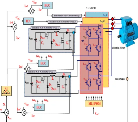
The figure 11 shows the block diagram of closed loop HCC and FLC for CHB-MLI fed Induction Motor System. The figure 12 shows the circuit diagram of closed loop HCC and FLC for CHB-MLI fed Induction Motor System. The FLC stimulate the optimized values of speed and produce the current reference for the HCC.
DC source
Buck -Boost
DC-DC
Converter
3-Phase
7-Level
Inverter
Induction
Motor
HC
I
refI
actN
refN
errorN
Pulse
generator
Duty Cycle
I
act*V
refFLC
Fig. 11 Block diagram of closed loop three-phase buck-boost converter fed MLI fed Induction motor current
control with HCC and FLC
The proposed FL speed controller participation for MLI fed drive is shown in figure 12. Here, the speed error (Δωr) between the set speed (reference speed-Nref) and rotor shaft speed (N) is used to produce the following inputs to the controller;
𝑢=Kp𝛥𝑤𝑟 (4)
[image:5.595.65.556.100.572.2]Comprehensive Analysis and Response of Closed Loop CBBCTPNLI System with PI and FLC
with crisp inputs and form the triangular control function. While increasing width of the triangular control function, action is fixed near the set point. The control functions are framed through linguistic variables. The proposed FLC linguistic variables for the speed control are classified into five groups.
HCC Iref
*IDC
GSB1 GSB2
HCC
IDC
*IDC
Nref
Ne
Nact
MLI-PWM
TA2
TA1
TA3
TA4
A B C
VDC
Induction Motor 3 Level CBH
L
SB-A1
+
-SB-A2
D1
D2
C1 C0
VDC
-+
Leg A Leg B
Leg C
Buck-Boost DC to DC Converter for Leg B Buck-Boost DC to DC Converter for Leg C
Buck-Boost DC to DC Converter for Leg A
Speed Sensor HCC
Iref
*IDC
GSB1 GSB2
HCC Iref
*IDC
L
SB-A1
+
-SB-A2
D1
D2
C1 C0
VDC
-+ Buck-Boost DC to DC Converter for Leg A
TA5 TA8
TA7 TA6
Vref
Iref
IDC
IDC
[image:6.595.307.546.51.229.2]FLC
Fig. 12 Closed loop three-phase buck-boost converter fed MLI fed Induction motor current control with HCC and
[image:6.595.54.293.137.349.2]FLC
Table. 2 FLC, fuzzy rule set table
e/Δe NL NS Z PS PB
NL Z PS NS NL PB
NS NS Z PB NS PS
Z NL PS Z NS PB
PS NS NL PB Z PS
PB PB NS PS NL Z
The knowledge base table (truth table) consists of 25 rules for calculating the result of the fuzzy implication practice, as presented in the Table 2. The fuzzy set table values are related with membership functions and the results are given to the fussy Inference engine (IE). Inference engine (IE) reproduces the human analysis (trained logic) through constructing fuzzy inference inputs and IF-THEN rules. After the defuzzification process the desired reference values are given to the control, which minimizes the speed error. Defuzzification is the process of producing inputs into one output. The two inputs used are,
1. Error (e) i.e. speed error ( we)
2. Changes of error or change of speed error (∆e).
The proposed fuzzy logic speed control used Mamdani type inference engine, which is well suited for proposed controller than Sugeno type. The centroid method defuzzification strategy is used here to extract the set out of output values. The figures 13 and. 14 show the inputs (variable-1 and 2) and output Mamdani inference engine maps. The inputs and output surface view mapping of the proposed FLC is given in figure 15. Here the fuzzy sets are compared between the two input variables and it produces the essential gain to maintain motor speed.
[image:6.595.308.545.247.421.2]Fig. 13 Membership function plot- Input variable 1
[image:6.595.43.296.419.495.2]Fig. 14 Membership function plot- Input variable 2
Fig. 15 Membership function plot- Output Variable VI. SIMULATION RESULTS AND DISCUSSION
[image:6.595.311.540.438.608.2]The simulation studies are performed for open loop and closed loop drive using PI and FLC. The closed simulation consists of inner loop (HCC to control the current) and outer loop acts as a speed control loop, which is done through PI and FLC. The simulated results are compared with FLC and HCC separately to validate the speed and current control for the drive. Apart from the combined HCC and FLC speed control for MLI drive, the simulation study is also carried out for proposed HCC and FLC separately to study the performance of the controllers individually. The proposed simulation model for FLC speed control with HCC controller is shown in figure 16 and PI based speed control with HCC is shown in figure 17.
Fig. 16 MATLAB-Simulink of Closed loop three-phase buck-boost converter fed MLI Induction motor drive
with PI based speed control and HCC
[image:7.595.304.560.63.174.2]As expected the open loop drive does not maintain the current and seep of the drive. When the HCC used in the drive through the DC-link current is maintained, the steady state stability of the drive is not maintained. Subsequently, when the drive is operated through HCC and conventional PI based speed controller, the drive reduces the speed error and improves the state stability.
Fig. 17 MATLAB-Simulink of Closed loop three-phase buck-boost converter fed MLI Induction motor drive
with HCC and FLC
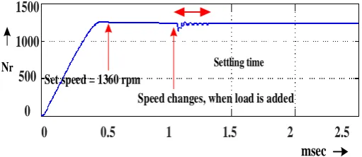
0 0.5 1 1.5 2 2.5
1500
1000
500
0
Nrmsec
Set speed = 1360 rpm
Speed changes, when load is added
Settling time
Fig. 18 Motor speed responses for PI controller with steady state and transient period
The speed response of the PI and FLC are shown in the figure 18 and 19. From the results, it is seen that FLC performs better than PI and maintain the speed responses in steady state stability.
0 0.5 1 1.5 2 2.5
1500
1000
500
0
Nrmsec
Set speed = 1360 rpm
[image:7.595.51.289.223.402.2]Speed changes, when load is added Settling time
Fig. 19 Motor speed responses for FLC controller with steady state and transient period
[image:7.595.315.555.280.385.2]The figure. 20 displays the waveform motor speed response for FLC controller with steady state and transient period. From these results, it could be observed that the closed loop structure FLC controls speed quickly when compared to PI controller. The consolidated speed control results for proposed FLC and PI are represented in Table. 3. The tables clearly show that the comparison of FLC performance is better than conventional controller (PI controller) in terms of the tr, tp, ts and ess. The steady state error on the FLC is 3.5 rpm, which is nearly 5 times smaller than conventional PI speed controller.
Table. 3 Time Domain Parameters
Controller tr (sec) tp (sec) ts (sec) ess in RPM ISE PI 11.65 10.3 16.9 14.7 93
FLC 6.3 1.2 9.9 3.1 27
[image:7.595.50.293.561.741.2] [image:7.595.302.551.582.669.2]Comprehensive Analysis and Response of Closed Loop CBBCTPNLI System with PI and FLC
200
0
-200
Vph
msec
Fig. 20 Simulation result of line to line voltage of CHB-MLI [100V/div] [1ms/div]
Vline 400
0
-400
[image:8.595.312.546.322.698.2]msec
Fig. 21 Simulation result of phase to phase voltage of CHB-MLI [200V/div] [1ms/div]
When the inverter fed drive is operated in different speeds, the modulation index of the inverter is changed using FLC speed controller and maintain the speed -torque characteristics. The figures 22 (a) and (b) shows the line voltage and its corresponding voltage THD for modulation index 0.5 and 0.866 respectively. The table. 4 and table. 5 represent the modulation index verses speed and modulation index verses line-line voltage respectively. The table. 6 represent the line-line voltage verses speed respectively. From the results it can be seen that, the line voltage and speed performances are linear. The voltage THD performance is maintained throughout the operating region of the MLI.
Fundamental Volatge
(a)
Fundamental Volatge
(b)
Fig. 22 Simulation results for voltage harmonic spectrum; (a) for MI 0.5, (b) for MI 0.866
Table. 4 MLI line to line voltage and voltage THD performance Vs Modulation Index Modulation index Line to line voltage
(Volts) voltage THD
0.2 56.2 9.56
0.4 118.6 8.95
0.6 186.5 8.56
0.8 215.3 8.21
0.866 286.6 7.93
Table. 5 Induction motor drive speed performance Vs Modulation Index
Modulation index Speed (RPM)
0.2 262
0.4 640
0.6 960
0.8 1250
0.866 1360
Table. 6 Induction motor drive speed performance Vs MLI output voltage
Line to line voltage (Volts) Speed (RPM)
56.2 262
118.6 640
186.5 960
215.3 1250
286.6 1360
Fundamental Current
(a)
Fundamental Current
[image:8.595.50.293.503.747.2](b)
The figures 23 (a) and (b) show the simulation results of current harmonic spectrum without HCC and with HCC respectively. From the results, it can be seen that HCC maintains the current harmonics (ITHD=1.56%). As a result, the HCC maintains the current performance (ripple free current). When the output mechanical load torque is applied to motor, the HCC is involved with speed controller and smooth the current. From the torque response, it can be seen that the load torque is uniform (for the speed of 1360rpm, 3.5 Nm)). Next the simulation study is experienced with HCC for the load torque performance. As expected HCC has given better torque performance.
Table. 7 HCC time response Parameters
FLC Controller
System Rise time
(sec)
System Peak time
(sec)
System Settling time (sec)
System Steady state
-error in RPM Without FLC
and HCC
10.5 11.3 12.3 12.2
With FLC and HCC
[image:9.595.45.292.219.376.2]9.8 9.9 10.2 3.5
Table. 8 Advantages of HCC on current ripple HCC Output Current Ripple
No 1.6A
Yes 0.5A
The table 7 and table 8 illustrates the HCC performance load torque ripple and FLC+ HCC performance. Though the voltage torque balance is maintained well, the drive speed transient is not as good as open loop conventional VSI drive. Hence, the MLI output voltage need to be controlled according to the speed command. The current profile is further maintained by adding hysteresis current controller on the DC to DC converter. The current controller improves the smooth torque performance with the wide range of speed.
VII. EXPERIMENTAL VALIDATION AND ITS RESULTS
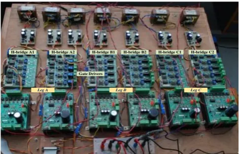
The prototype is developed for 3Ф DC to DC converter with five level CHBMLI and its HCC and FLC speed control.
H-bridge A1
Leg A Leg B Leg C
H-bridge A2 H-bridge B1 H-bridge B2 H-bridge C1 H-bridge C2
[image:9.595.304.550.389.588.2]Gate Drivers
Fig. 24 Experimental power module for three phase 5 level CHB-MLI
Hardware Description
A 1kW six DC to DC converter connected three-phase five-level CHB-MLI drive connected with 1 HP, 50Hz, 4-pole, 1450rpm; three-phase SCIM is built for the experimental purpose. In addition to the experimental setup used in chapter 3, the speed and current are measured form the motor and inverters input (DC-Link) using digital Texas instrument speed sensor and hall current sensor respectively. The converter and inverter MOSFETs are switched through the closed loop current controller (HCC) and speed controller (FLC). The IR driver circuits -IRS2110 for converter and MLI are continuously providing gating signal from the HCC and FLC controller according to the change in the motor speed and load. The inductor motor relates to mechanical break drum load arrangement and is used as a load to test the speed- torque response of the drive. The speed is measured through digital scope and drive load torque is measured through monad rotary torque sensor (Optical type with sensor rated output 2mv/V). The entire control system is validated through SPARTAN-III-3A XC3SD1800A-FG676 DSP-FPGA microcontroller and experimental results are measured through 2-channel keyset DSO.
(i)Peripheral interface circuits: To transfer the digital signals from the FPGA board to the MLI, two main boards peripheral interface circuits (1. interface board and 2.gate driver board) are developed.
Fig. 25 DC supply for gate driver Xilinx SPARTAN-III-3AXC3SD1800A-FG676DSP- FPGA Board
The FPGA board is shown in Fig. 26. The specifications are as follows
3MHz to 100MHZ oscillator ( On-board programmable) Eight bit DAC and ADC interface
VSDA-03Add on card with SDA bus for ADC and DAC Serial port -RS232
Two 16 channel PWM signal
[image:9.595.47.290.604.760.2]Comprehensive Analysis and Response of Closed Loop CBBCTPNLI System with PI and FLC
Fig. 26 Schematic view of SPARTAN-III-3A XC3SD1800A - FG676 DSP-FPGA Experimental Validation and its Results
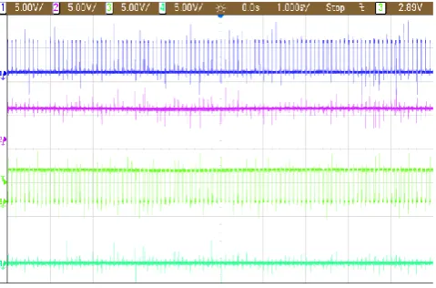
[image:10.595.47.291.51.253.2]The figure 27 shows the converter-1 and converter-2 duty cycle for the CHB-MLI phase-A H-bridges, when speed of the motor is kept as 1360 rpm. During this time the HCC current band is fixed as 2.4 A.
Fig. 27 Experimental results for converter-1 and converter-2 duty cycle
From the results, it could be observed that the converters work with their full degree of freedom and providing continuous current without ripple. When the motor speed is close to 1360 rpm with 2 Nm load torque, the FLC speed response is tested. The CHB-MLI results of Vl and Vp are displayed in the figures 28 and 29 respectively. The motor current waveform of the motor is shown in the Figure. 30. From the results, it could be observed that the HCC and FLC help to provide smoother current response, which helps the smoother torque response. To investigate the FLC speed performance, the motor load is changed from no-load to practical load. During this period, the motor speed is quickly maintaining its 1360 rpm set speed. Based on the experimental test, it could be evident that FLC behaves to maintain the motor speed for loads irrespective of the drive mechanical load.
[image:10.595.310.544.257.438.2]Fig. 28 Experimental results of line to line voltage of CHB-MLI [150V/div] [1ms/div]
Fig. 29 Experimental results of phase to phase voltage of CHB-MLI 50V/div] [1ms/div]
0.5Amps/Div
IS
msec
Fig. 30 Experimental results for motor stator current [1A/div] [1ms/div]
[image:10.595.50.290.363.521.2]Hence, the MLI is required to deal with closed speed and current controller for the better motor drive performance.
VIII. CONCLUSIONS
In this paper a 3 Ф three-phase five-level DC to DC converter five-level CHB-MLI fed three-phase IM drive with PI & FLC are modelled and investigated using MATLAB/Simulink The simulation study results confirmed the advantages of the HCC and FLC performance against different speed- torque characteristics of the drive. The proposed CHB-MLI has maintained their voltage and current THD for the entire modulation ranges. The time demand response of the FLC has performed better than PI controller with the settling-time of 9.9 sec and steady-state error has reduced to 3.1 RPM. The FPGA SPARTAN-3 controller based experimental setup is realized and tested for the proposed HCC and FLC speed controller. The experimental results are conforming simulation results and prove the FLC performance against speed and HCC. REFERENCES
1. Lin, F.J., Lin, C.H., and Shen, P.H.,Jul. (2004) „Variable-structure
control for a linear synchronous motor using a recurrent fuzzy neural network‟, IEE Proceedings - Control Theory and Applications, vol. 151, no. 4, pp. 395–406.
2. Jung,J.W., Kim,T.H., and Choi, H.H., (2010) „Speed control of a
permanent magnet synchronous motor with a torque observer: a fuzzy approach‟, IET Control Theory & Applications, vol. 4, no. 12, pp. 2971–2981.
3. Duranay Z.B., and Guldemir, H.,Mar. (2018) „Selective harmonic
eliminated V/f speed control of single-phase induction motor‟, IET Power Electronics, vol. 11, no. 3, pp. 477–483.
4. Devanshu, A., Singh,M., and Kumar, N., (2018) „Sliding Mode
Control of Induction Motor Drive Based on Feedback Linearization‟, IETE Journal of Research, pp. 1–14.
5. Lu, C.-H. T. H.-C., (2000) „Observer-Based Speed Estimation Method
for Sensorless Vector Control Using Artificial Neural Network‟, Electric Machines & Power Systems, vol. 28, no. 9, pp. 861–873.
6. Schild, A., Lunze, J., Krupar,J., and Schwarz,W., (2009) „Design of
Generalized Hysteresis Controllers for DC–DC Switching Power Converters‟, IEEE Transactions on Power Electronics, vol. 24, no. 1, pp. 138–146.
7. Abderrezek.H.,and Harmas, M.N., (2014) „PSO Based Adaptive
Terminal Sliding Mode Controllers for a DC-DC Converter‟, International Journal of Computer Theory and Engineering, vol. 6, no. 4, pp. 302–306.
8. Venkatramanan,R., Sabanovic, A.,and Cuk, S., (1985) „Sliding mode
control of DC-to-DC converters‟, in Proc. IEEE Conf. IECON, pp. 251-258.
9. Huang, S.P., Xu, H.Q., and Liu.Y.F., (1989) „Sliding mode controlled
Cuk switching regulator with fast response and first-order dynamic characteristics‟, in Proc. IEEE PESC Rec., pp. 124-129.
10. FossasE., Martinez, L.,and Ordinas,J., (1992) „Sliding-mode control
reduces audio susceptibility and load perturbation in the Cuk converter‟, IEEE Trans. Circuits Syst. I. Fundam. Theory Appl., vol. 39, no. 10, pp. 847-849.
11. Shtessel,Y.B., Zinober, A.S.I and Shkolnikov, I.A., (2002) „Boost and
buck-boost power converters control via sliding modes using method of stable system centre‟, in Proc. 41st IEEE Conf. Decision Control, vol. 1, pp. 346-347.
12. Tan,S.C., Lai, Y.M., Tse,C.K., (2008) „General design issues of
sliding-mode controllers in dc-dc converters‟, IEEE Trans. Industrial Electronics., vol. 55, no. 3, pp. 1160–1174.
13. Tan, S.C., Lai, Y.M., Cheung, M.K.H., and Tse, C.K., (2005) „On the
practical design of a sliding mode voltage controlled buck converter‟, IEEE Trans. Power Electron., vol. 20, no. 2, pp. 425–437.
14. Raviraj, V.S.C.,and Sen,P.C., Mar./Apr. (1997) „Comparative study of
proportional integral, sliding mode, and fuzzy logic controllers for power converters‟, IEEE Trans. Ind. Appl., vol. 33, no. 2, pp. 518–524.
15. Perry,A.G., Guang,F., Liu, Y.F., and Sen, P.C., (2004) „A new sliding
mode like control method for buck converter‟, in Proc. IEEE PESC Rec., vol. 5, pp. 3688–3693.
16. Nguyen., V.M., and Lee, C.Q., (1995) „Tracking control of buck
converter using sliding-mode with adaptive hysteresis‟, in Proc. IEEE PESC Rec., vol. 2, pp. 1086–1093.
17. Tan,S.C., Lai, Y.M., Tse,C.K., and Cheung, M.K.H., (2006)
„Adaptive feed forward and feedback control schemes for sliding mode controlled power converters‟, IEEE Trans. Power Electron., vol. 21, no. 1, pp. 182–192.
18. Sukumar, D.,Ranjan, V., and J., Rabi, (2010) „FLC based adjustable
speed drives for power quality enhancement‟, Serbian Journal of Electrical Engineering, vol. 7, no. 2, pp. 217–229.
19. Chaturvedula,U.P.K., (2017) „Integrated Three Phase Hybrid Cascaded
MLI Fed Induction Motor Drive for Energy Management in Electric Vehicles‟, International Journal for Research in Applied Science and Engineering Technology, vol. 36, no. 12, pp. 1359–1366.
20. Hayim,A., Knieser, M., and Rizkalla,M., (2010) „DSPs/FPGAs
Comparative Study for Power Consumption, Noise Cancellation, and Real Time High Speed Applications‟, Journal of Software Engineering and Applications, vol. 03, no. 04, pp. 391–403.
21. Prasad, J.S., Obulesh, Y.P., and Babu, C.S., (2016) „FPGA (Field
Programmable Gate Array) controlled solar based zero voltage and zero current switching DC–DC converter for battery storage applications‟, Energy, vol. 106, pp. 728–742.
22. Chen,Y., Chang, C.Y., and Yan,Y., (2013) „FPGA-Based Expert PID
Controller for Buck DC-DC Converter‟, Applied Mechanics and Materials, vol. 431, pp. 215–220.
23. Rajkumar,M.V., Prakasam, P., and Manoharan, P.S., (2016)
„Investigational Validation of PV Based DCD-MLI Using Simplified SVM Algorithm Utilizing FPGA Tied with Independent Sources‟, Circuits and Systems, vol. 07, no. 11, pp. 3831–3848.
Biographical notes: Chinnapettai Ramalingam Balamurugan was born in 1978 in Kumbakonam. He has obtained B.E (Electrical and Electronics), M.E (Power Electronics and Drives) and Ph.D (Instrumentation Engineering- Power Electronics) degrees in 2000, 2005 and 2015 respectively from Arunai Engineering College, Tiruvannamalai, Sathyabama University, Chennai and Annamalai University, Chidambaram. He has been working in the teaching field for about 14 years. His areas of interest include power electronics, electrical machines and solar energy systems. He has 110 publications in international journals. His research papers 80 have been presented in various/IEEE international/national conferences. Currently, he is working as Professor and Head in the Department of EEE, Karpagam College of Engineering, Coimbatore. He is guiding 7 Ph.D scholars under anna university, Chennai. He got best faculty awards for nearly five times. He wrote more than thirty books. He is the reviewer for many reputed journals. He is a life member of Instrument Society of India and Indian Society for Technical Education. He is a member in IEEE. He cleared NPTEL certification Course. Received “DIGITAL GURU AWARD AND CASH PRIZE” for valuable contributions towards the digital content developed for Power Electronics.. Contact number- +91-9894522351. E-mail: [email protected].
![Fig. 21 Simulation result of phase to phase voltage of CHB-MLI [200V/div] [1ms/div]](https://thumb-us.123doks.com/thumbv2/123dok_us/8215864.264186/8.595.312.546.322.698/fig-simulation-result-phase-phase-voltage-chb-mli.webp)