Ames Laboratory Publications
Ames Laboratory
5-15-2003
Microelectromagnetic ferrofluid-based actuator
Y. Melikhov
Iowa State University
S. J. Lee
Iowa State University
David C. Jiles
Iowa State University, [email protected]
D. H. Schmidt
Iowa State UniversityMarc D. Porter
Iowa State UniversitySee next page for additional authors
Follow this and additional works at:
http://lib.dr.iastate.edu/ameslab_pubs
Part of the
Electromagnetics and Photonics Commons
,
Electronic Devices and Semiconductor
Manufacturing Commons
,
Engineering Physics Commons
, and the
Fluid Dynamics Commons
The complete bibliographic information for this item can be found at
http://lib.dr.iastate.edu/
ameslab_pubs/150
. For information on how to cite this item, please visit
http://lib.dr.iastate.edu/
howtocite.html
.
Microelectromagnetic ferrofluid-based actuator
Abstract
Computer simulations were used to investigate the performance of a microscale ferrofluid-based magnetic
actuator developed for liquid dispensing in microfluidic channels. The actuation was based on the movement
of a ferrofluid plug in a magnetic field gradient generated by on-chip effectively infinite parallel conductors.
The movement, positioning, and retaining of ferrofluid plugs with different lengths at various locations along a
microfluidic channel were investigated for two cases. In case (a), the magnetic field gradient was generated by
a single conductor; when the ferrofluid reached its equilibrium position, the current was switched off and the
nearest neighbor conductor was energized. A similar, consecutive on/off current switching was performed for
case (b), where a set of conductors was energized simultaneously.
Keywords
Microelectronics Research Center, Microanalytical Instrumentation Center, Conductors, Ferrofluids,
Magnetic fields, Microdluidics, computer simulation
Disciplines
Electromagnetics and Photonics | Electronic Devices and Semiconductor Manufacturing | Engineering
Physics | Fluid Dynamics
Comments
The following article is from
Journal of Applied Physics
93 (2003): 8438 and may be found at
http://dx.doi.org/10.1063/1.1540164
.
Rights
Copyright 2003 American Institute of Physics. This article may be downloaded for personal use only. Any
other use requires prior permission of the author and the American Institute of Physics.
Authors
Y. Melikhov, S. J. Lee, David C. Jiles, D. H. Schmidt, Marc D. Porter, and Ruth Shinar
Microelectromagnetic ferrofluid-based actuator
Y. Melikhov, S. J. Lee, D. C. Jiles, D. H. Schmidt, M. D. Porter, and R. Shinar
Citation: Journal of Applied Physics 93, 8438 (2003); doi: 10.1063/1.1540164
View online: http://dx.doi.org/10.1063/1.1540164
View Table of Contents: http://scitation.aip.org/content/aip/journal/jap/93/10?ver=pdfcov
Published by the AIP Publishing
Articles you may be interested in
Ordered microdroplet formations of thin ferrofluid layer breakups
Phys. Fluids 22, 014105 (2010); 10.1063/1.3298761
Magnetically actuated microrotors with individual pumping speed and direction control
Appl. Phys. Lett. 95, 023504 (2009); 10.1063/1.3176969
“Stick and slide” ferrofluidic droplets on superhydrophobic surfaces
Appl. Phys. Lett. 89, 081911 (2006); 10.1063/1.2336729
Dielectric relaxation of chained ferrofluids
J. Chem. Phys. 116, 6731 (2002); 10.1063/1.1462042
Electromagnetic micromotor for microfluidics applications
Appl. Phys. Lett. 79, 1399 (2001); 10.1063/1.1398319
Magnetic Fluids
Gary Friedman, Chairman
Microelectromagnetic ferrofluid-based actuator
Y. Melikhov,a)S. J. Lee, and D. C. Jiles
Ames Laboratory, Iowa State University, Ames, Iowa 50011
D. H. Schmidt, M. D. Porter, and R. Shinara)
Microelectronics Research Center and Microanalytical Instrumentation Center, Iowa State University, Ames, Iowa 50011
共Presented on 15 November 2002兲
Computer simulations were used to investigate the performance of a microscale ferrofluid-based magnetic actuator developed for liquid dispensing in microfluidic channels. The actuation was based on the movement of a ferrofluid plug in a magnetic field gradient generated by on-chip effectively infinite parallel conductors. The movement, positioning, and retaining of ferrofluid plugs with different lengths at various locations along a microfluidic channel were investigated for two cases. In case共a兲, the magnetic field gradient was generated by a single conductor; when the ferrofluid reached its equilibrium position, the current was switched off and the nearest neighbor conductor was energized. A similar, consecutive on/off current switching was performed for case共b兲, where a set of conductors was energized simultaneously. © 2003 American Institute of Physics.
关DOI: 10.1063/1.1540164兴
I. INTRODUCTION
Magnetic field gradient is widely used for magnetic trap-ping, transport, and filtration/separation of magnetic particles.1–3Magnetic field gradient can also be used to ma-nipulate a ferrofluid, which is a stable suspension of fine
共⬃10 nm diameter兲, single-domain, ferrimagnetic particles in an aqueous or organic carrier. As a result, ferrofluids can be used in a wide range of applications4 – 6 by exploiting both their magnetic and liquid properties.
This work describes a microelectromagnetic 共MEMag兲 device in which the movement of a ferrofluid plug is actu-ated by consecutive switching of on-chip current-carrying conductors. The movement of the ferrofluid plug can be used to dispense a liquid that is in direct or indirect contact with the ferrofluid. Hence, this device is being developed for de-livery of microliter and nanoliter amounts of fluids in micro-fluidic channels for biological and chemical applications. The ability to use on-chip conductors to drive the ferrofluid plug results in devices that are more flexible in design and, consequently, more versatile in function in comparison with devices based on moving permanent magnets.6
II. DESCRIPTION OF THE PROBLEM
The device consisted of on-chip, parallel, effectively in-finite conductors. In case共a兲, a single conductor is energized, while several parallel conductors are energized simulta-neously in case 共b兲. The width of each conductor was 100
m and the height was 1 m. The distance between the centers of two adjacent conductors was 200 m. These di-mensions allowed us to simplify the problem to a two-dimensional case as shown in Fig. 1 for case 共b兲.
Calculations were performed assuming Al conductors, which can handle a maximal current density of 10⫺3A/m2, limiting the maximal operational current to 100 mA. The ferrofluid plug was placed in a long capillary共100⫻100m2 cross section兲 that was situated 100 m above the MEMag device, parallel to its plane and perpendicular to the direction of the current flow 共see Fig. 1兲. In all calculations, a ferro-fluid with EMG 900 共Ferrotec兲 properties was considered. This ferrofluid exhibits a superparamagnetic behavior with a saturation magnetization of 72 kA/m.
Using finite element method, the Maxwell equations were solved numerically for the entire system. In order to calculate the magnetic force acting on a ferrofluid plug, the energy, E, of the plug in the external magnetic field was calculated as a function of the distance, x, between the cen-ters of the current-carrying conductor and the plug
E共x兲⫽⫺
冕
V
M•BdV, 共1兲
where B is magnetic flux density, M is magnetization, and V is the volume of the plug. The capillary parallel component of the magnetic force, F(x), acting on a plug is the deriva-tive of the energy共1兲
F共x兲⫽dE共x兲
dx . 共2兲
a兲Authors to whom correspondence should be addressed; electronic mail:
[email protected] and [email protected]
JOURNAL OF APPLIED PHYSICS VOLUME 93, NUMBER 10 15 MAY 2003
8438
0021-8979/2003/93(10)/8438/3/$20.00 © 2003 American Institute of Physics
Equation共2兲was used to compute F(x) for different lengths,
L of the ferrofluid plug.
As mentioned, the movement of the plug was investi-gated for two different cases:共a兲consecutively inserting the next neighbor conductor and simultaneously shutting down the previously energized conductor, and 共b兲 consecutively inserting every nth conductor (n⬎2 and constant兲and simul-taneously shutting down the previously energized neighbor-ing conductors共see Fig. 1 for n⫽3). The insertion and shut-down were carried out when the plug reached its equilibrium position, i.e., the total magnetic force was zero.
III. RESULTS AND DISCUSSION
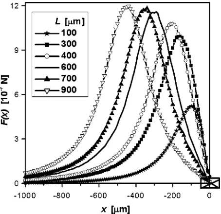
The magnetic force as a function of x for case 共a兲 is shown in Fig. 2 for ferrofluid plugs with different lengths. It was found that the magnetic force has a symmetry F(⫺x)
⫽⫺F(x), enabling plug movement in opposite directions:
positive F(x) values cause plug movement towards the en-ergized conductor, which is left to right in the Fig. 2. Nega-tive F(x) values共not shown兲represent movement in the op-posite direction. It can also be seen that F(x) has a
maximum, FM AX, and for L⭓300m共this limit depends on the dimensions of the plug and conductor兲, the position of
[image:5.612.328.550.50.264.2]FM AX, is at x⫽⫺L/2. At this position, the entire plug is placed as close as possible to the conductor共i.e., one of the edges of the plug is exactly at x⫽0) and all parts of the plug are subjected to the positive force. For L⭐300 m 共not shown兲, the position of the maximum is near 100m. FM AX initially increases linearly with increasing length 共i.e., vol-ume兲of the ferrofluid plug. However, as L further increases, the increase in FM AX becomes more gradual until a satura-tion value is reached 共see Fig. 3兲. This behavior is due to a decrease in the magnetic force acting on parts of the plug that are more distant from the energized conductor 共i.e., where the magnetization approaches zero兲. For case 共a兲, a FIG. 1. Schematic view of the device design geometry for case共b兲. The
[image:5.612.91.260.52.160.2]conductors are perpendicular to the shown plane. The energized conductors, separated by a distance a, are presented by crossed rectangles. The arrows indicate possible directions for ferrofluid共FF兲plug movement.
[image:5.612.62.289.502.722.2]FIG. 2. The magnetic force F(x) as a function of the distance x for different ferrofluid plug lengths for case共a兲. An energized conductor is presented as the crossed rectangle. The applied current is 10 mA.
FIG. 3. The dependence of the maximal value of the magnetic force FM AX
on the length L of a ferrofluid plug for case共a兲. The applied current is 10 mA.
FIG. 4. The magnetic force F(x) as a function of the distance x for different lengths of ferrofluid plugs for case共b兲. Energized conductors are shown as crossed rectangles. The applied current is 10 mA.
8439 J. Appl. Phys., Vol. 93, No. 10, Parts 2 & 3, 15 May 2003 Melikhovet al.
[image:5.612.323.552.511.721.2]plug with any length can be moved and its equilibrium po-sition is reached when the center of the plug is located just above of the center of current-carrying conductor.
The magnetic force as a function of x for case 共b兲 is depicted for different values of L in Fig. 4, where a value of
n⫽3 was chosen as an example. It was observed that F(x) in this case possesses a spatial periodicity in x with a period of a⫽200nm and, at a first approximation, the periodicity in F(x) with respect to L is 2a. Therefore, only plugs with length 0⭐L⭐2a will be examined herein. As for case 共a兲, positive and negative values of F(x) cause plug movement in opposite directions. Note, that for case共b兲there are many positions where the magnetic force is equal to zero共see Fig. 4兲. These positions are at x⫽ka/2, where k is an integer.
However, only half of these positions are stable and this half is different for different L values.
When 0⭐L⭐a the movement of the plug closely
paral-lels case共a兲: its equilibrium共and stable兲position is reached when the center of the plug is just above the center of one of the current-carrying conductors, i.e., k is even. However, for a plug with a⭐L⭐2a the equilibrium position is reached when the plug center is exactly in the middle between two nearest current-carrying conductors, i.e., k is odd.
For case共b兲, plugs with a length close to L⫽ma, where m is an integer共see Fig. 4 for m⫽1; i.e., L⫽600m兲, will not move, independent of the magnitude of the current; that is, F(x) is zero at any position.
It is worth noting that for plugs with length a/2 or 3a/2, the maximum magnetic force for case 共b兲 is larger than for case共a兲 共compare F(x) values for 300 and 900m plugs in Figs. 2 and 4兲. This difference is caused by the presence of several energized conductors, which affect the magnetic flux density and the gradient.
It was found also that for both cases 共a兲 and 共b兲 the magnetic force shows a square-law increase with increasing current. This behavior reflects the relatively low current 共up to 100 mA兲 used to energize the MEMag device. In such
cases, the magnetic field is proportional to the current and the magnetization of the ferrofluid is a linear function of magnetic field, far from the saturation region. Increasing the current further 共e.g., by using gold, rather than aluminum, conductors that can handle a significantly higher current den-sity, i.e., up to 1 A/m2), will increase the magnetic force but disturb the square-law increase, leading to a more linear behavior. However, one should be aware of the possibility of breakage of the ferrofluid plug into smaller parts for case共b兲 due to adjacent conductors that exert force in opposite direc-tions; this situation can potentially disjoint or rupture the plug.
In summary, two cases for an on-chip microelectromag-netic device were evaluated, where a ferrofluid plug is used as an actuator for delivery of microliter or nanoliter amounts of fluids. The device properties were studied numerically us-ing finite element analysis. It was shown that the movement of a ferrofluid plug in a microfluidic channel could be con-trolled utilizing different designs of microelectromagnets and different plug lengths. Additionally, depending on the design parameters, ferrofluid plugs can serve as on-chip valves. The utility of on-chip designs for ferrofluid-actuated devices for chemical and biological applications is currently under in-vestigation.
ACKNOWLEDGMENTS
This work was supported by the Seed-Funding Program of the Institute for Physical Research and Technology of Iowa State University, Ames, Iowa.
1M. Drndic, C. S. Lee, and R. M. Westervelt, Phys. Rev. B 63, 085321 共2001兲.
2
T. Deng, G. M. Whitesides, M. Radhakrishnan, G. Zabow, and M. Prent-iss, Appl. Phys. Lett. 78, 1775共2001兲.
3G. P. Hatch and R. E. Stelter, J. Magn. Magn. Mater. 225, 262共2001兲. 4K. Komiya, I. Itoh, and Y. H. Gashi, Rev. Sci. Instrum. 63, 3677共1992兲. 5
N. E. Greivell and H. Blake, IEEE Trans. Biomed. Eng. 44, 129共1997兲. 6A. Hatch, A. E. Kamholz, G. Holman, P. Yager, and K. F. Bohringer, J.
Microelectromech. Syst. 10, 215共2001兲.
8440 J. Appl. Phys., Vol. 93, No. 10, Parts 2 & 3, 15 May 2003 Melikhovet al.