International Journal of Innovative Technology and Exploring Engineering (IJITEE) ISSN: 2278-3075, Volume-8 Issue-10, August 2019
A Solar Powered SRM Drive for EVS using Fuzzy
Controller
T.vinay kumar, m. Kiran kumar
Abstract: This project presents the switched reluctancemotor (SRM) with hybrid renewable system. Switched Reluctance Motors (SRM)plays an very important role in the industrial applications, due to these advantages over conventional motors. Due to the ruggedness and simple construction this SRM motor plays a vital role in the industrial applications. They are various methods are applied for control the speed of SRM motor by the hybrid system. The hybrid system energy, has two or more renewable energy source are been used together in order to increase the efficiency of the system and to provide great balance in the system energy. The PV have different type ofcharacteristics when compared to ICEs, Maximum power point tracking (MPPT)withsolarenergyutilizationareoneuniquefeatureforthePV-fed electricalvehiclesEV. Thismatterisdonewhenthemuti-objective function is applied by the proposed system which includes both Torque ripple and speed error. This controller is implemented for 4-kW SRM. In this we are combining the solar pv panels and battery. Hybrid renewable applied in energy storage systems like technoogies of battery, magnetic energy,pumped storages, capacitorsandcompressedairarethealternativesfortheoperator of an EV Electrical vehicle grid which can consume energy from energy production. The simulation results confirm by using ANFIS we can reduce the current oscillations , improve in dynamic performance and we can reduce the torqueripple.
Index Terms: Photovoltaics (PVs), Switched reluctance motor (SRM), Electrical vehicles (EVs), Tri-port converter, Power flow control.
I. INTRODUCTION
Electric vehicles are automobiles, which are powered by electrical engine and electrical energy. Electrical vehicles are also been known as the electrical drive vehicles. For propulsion [1] an electric vehicle use one or more electric motors. From the electricity the electric vehicle are powered by the collector system from vehicle sources, or with the battery combined with the generator to produce electricity from fuel [2]. he electric vehicle motors which includes the under water vehicles, road, aircraft, electric space craft and rail vehicle. In the mid-19th century the electric vehicle (EV)
cametoexistence.Forthepropulsionofthevehiclemotorthe electricity has been preferred for operating. The gasolinecars can not be achieved by the operation and providing level of ease of operation and comforts [5]. Due The development of electric vehicles is a very important and prospective process. Electric vehicles are powered by an electric motor instead of an internal combustion engine[6-7].
Electric vehicles are 100% eco-friendly and they do not emit any toxic gases like CO2, N2 etc. which causes Global warming.Buttherearesomedownsidesinthecaseofelectric
Revised Manuscript Received on August 05, 2019.
T. VINAY KUMAR, M.Tech, Department Of Electrical and
Electronics Engineering, KLEF, Guntur, Andhra pradesh, india
Dr. M. KIRAN KUMAR, ASSOC. Professor, Department. Of
Electrical and Electronics Engineering, KLEF, Guntur, Andhra pradesh,
vehicles (EVs). As the battery technologies are limited as of now,sothedrivingrangeisveryless.Sothatitmakesreduce the usages in many applications of electric vehicles. The motor driver in earlier days, permanent magnet (PM) machines are used for the high performances [8]. Field windings are not present in the permanent magnet (PM) machine. The permanent magnet machine is provided. Rare earth materials are been used very commonly. The applications of electrical vehicle (EV) are reduce because of using permanent magnet
(PM) machines
Inordertoreducetheseissueaphoto-voltaic(PV)isused
forthepowersupplyandSRMswitchedreluctancemotorare used for the motor drive [10]. By presenting PV board on the highestpointofthevehicle,anappropriatevitalitysourcecan be accomplished. PV board has low power thickness for footing drives; they can be utilized to charge the batteries. (SRM) switched reluctance motor does not have any rare earth materials. SRM is one type of stepper motor. Reluctance torque is needed to runs the motor [11]. Rather than rotor the power has been delivered to the stator (case), it is not like common DC motor that are presented. Due to the flow of power that is from the stator rather rotor. So there mechanical design is been greatly simplifies because the power does not need to flow from the rotor. Forwallcovering power we need some power electronic switches to different windings[12-13]. As the technology improves the electronic switches are used for switching the windings and in modern stepper motor the design of (SRM) switched reluctance motor is more popular [14].
Torque ripple is the major drawback in switched reluctance motor . In order to get the optimum performance for SRM switched reluctance motor we need to design the hybrid fuzzy controller with the load disturbance and variations. The purpose of hybrid fuzzy controller is to get desired performance of SRM[15]. We need PI discrete and fuzzy logic controller algorithm. Speed error and changes in speed can be employed with the controller. The fuzzy controller helps to improve the performance in the system in steadystateasaswellastransientGenerally,Byandlarge,the PV-sustained EV has a comparable structure to the cross breed electrical vehicle, whose interior burning motor (ICE) is supplanted by the PV board. The PV-encouragedEV to are the frae framework isrepresented in Fig.1.Its key is to pcomponents includes an off-board charging port station, a pv, batteries and power converters So as to diminish the vitality transformation forms, one methodology is to update the engine toincorporate
some ready charging functions. Forinstance, paper designs a
contents in the back electromotive force (EMF). Another solutionisbasedontraditionalSRM.Paperachievesonboard charging and power factor correction in a 2.3-kW SRM by
employing machine
The concept of a modular structure of driving topology is proposed in the paper. Based on intelligent power modules (IPM), a four-phase half-bridge converter is employed to achieve driving and grid-charging. Although modulation supportsmassproduction,theuseofhalf/fullbridgetopology reduces the system reliability (e.g. shoot-through issues). Paper develops a simple topology for plug-in hybrid electric vehicle (HEV) that supports flexible energy flow. But for grid charging, the grid should be connected to the generator rectifier that increases the energy conversion process and decreases the charging efficiency. Nonetheless, an effective topology and control strategy for PV-fed EVs is not yet developed. Because the PV has different characteristics to ICEs, the maximum power point tracking (MPPT) and solar energy utilization are the unique factors for the PV-fedEVs.
II. SRMDRIVE
The idea of switched reluctances was set up in 1838 yet the engine couldn't understand its maximum capacity until the modern era of control electronicand computer - progra aid programming supported electromagnetic
structure in the motor. SRM's switched reluctance motor are electrically com mutated AC machines and are referred to as factor hesitance engine as concentrated by Lawrenson et al (1980). They are in excess of a rapid stepper engine, coming up short on the typical costly lasting magnets. It joins a considerable lot of the alluring characteristics of Induction-motor drives, DC commutator engine drive, just as Permanent Magnet(PM) brush less D.C frameworks. SRM is rough and basic in development and conservative when contrasted and the synchronous engine and the acceptance engine. They are known to have high pinnacle torque-to-latency proportions and the rotor mechanical structure is
appropriate for rapid applications conceptof
[image:2.595.50.280.273.732.2]switchedreluctance motor was established in1969
Fig. 1: Switched Reluctance Motor
A. Construction of Switched Reluctance motor
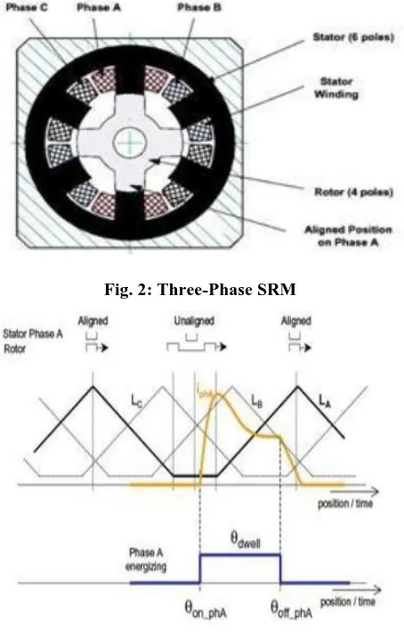
[image:2.595.314.541.294.649.2]The switched reluctance motor has both notable shaft stator and rotor, similar to variable hesitance engine (Nazar 1969),howeverthey are intended for various applications,and in this way, with various execution necessities. A stepper engine is intended to make it reasonable for open circle position and speed control in lower applications, where proficiencyisn'tasignificantfactorasappearedinFig2.Then again an exchanged hesitance engine is utilized in factor speed drives and normally intended to work productively for wide scope of speed and torque and requires rotor position detecting. Here, the oppositely inverse stator post windings are associated in arrangement and they structure one stage.In this way, the six stator shafts comprise three stages. At the point when the rotor shafts are lined up with the stator posts of a specific stage, the stage is said to be in an adjusted position. Correspondingly, if the between polar hub of the rotor is lined up with the stator posts of a specific stage, the stage is said to be in anunaligned.
Fig. 2: Three-Phase SRM
Fig.3: PhaseEnergizing
Fig.1 shows the circuit diagram of projected single stage single switch isolated buck-boost buck converter topology connected to the diode bridge rectifier(DBR).
[image:2.595.57.252.509.723.2]International Journal of Innovative Technology and Exploring Engineering (IJITEE) ISSN: 2278-3075, Volume-8 Issue-10, August 2019
III. PROPOSED TOPOLOGY AND
OPERATIONALMODES
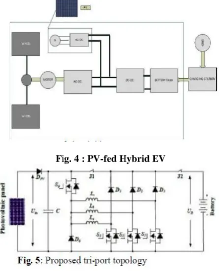
[image:3.595.56.279.178.453.2]The proposed technology consists of four ports with four energy terminals. In this battery,pv and SRM are connected.Power converter is used, which consists of eight switching devices (S0~S7), four 8 diodes (f)Operation at Mode-6 : When PV is in idle condition and battery is charged. When battery is been charged by the pv panel when EV is parked under the sun. The relay J1 and relay J2 both conducting.
Fig. 4 : PV-fed Hybrid EV
Different Modes of actions for J1 and J2
(a) Operation at Mode-1: In this mode the PV is major source which helps to drive the switched reluctance motor and for the battery charging.During light loads of movement the amount of power generated by the PV is more than reluctance motor needed. In this mode relay J1 is turn-off and relay J2 isturn-on.
(b) Operation at Mode-2: In this mode both the PV and the battery acts like power sources for driving the SRM. During heavy loads of operation of SRM like more acceleration or driving uphill. In this case SRM receives power from both the source andbattery.
(c) Operation at Mode-3: In this mode the battery is in idle condition and the PV is the only the source to drive the
(d) Operation at Mode-4: When In this mode of operation the PV is in idle condition and battery is the power source to drive the SRM. In some cases due to less amount of solar irradiation the PV is not able to generate power so thebattery is only the source to drive theSRM.
Fig.9: (6d) Operation at Mode-4
Fig.10: (6e) Grid Charging Mode-6
Fig.11: (6f) PV Source Charging Mode-6
IV. CONTROL STRATEGY FOR
GRIDCHARGING
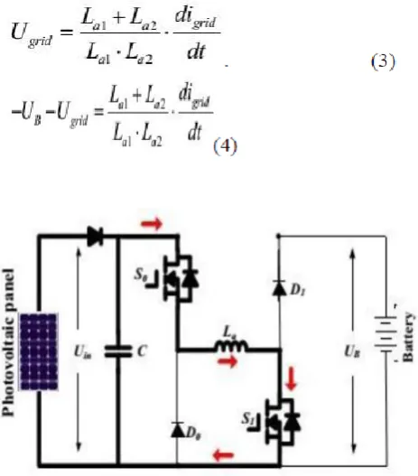
The single phase grid charging are supported by the topology that has been proposed. As there are four base charging states in this So is off. When the grid voltage is more than zero there are two states are available. The voltage in the grid charges the phase winding La2, the switches S1 will be in off and switch S1 conducts, the S1nad S2 switches are in series to the phase winding in order to charge battery.When the phase windings are connected that charges battery.
Fig.12: (7a) Grid charging state
Fig.13:(7b) Grid charging state at 2 (U grid >0)
(7c) Grid charging state 3
International Journal of Innovative Technology and Exploring Engineering (IJITEE) ISSN: 2278-3075, Volume-8 Issue-10, August 2019
(1)
(2)
[image:5.595.315.545.50.244.2]Two states are been introduced. When the instanteneous momentary voltage will be less than zero. The switches S1 and S2 direct the voltage and the winding La1 and La2 charges the network . When switch S2 is off and the switch S1 is turned-on and conducting in La1 and La2 which the battery is charged . The comparing equations are
[image:5.595.55.287.194.458.2]Fig : 14 Charging at phase inductance
[image:5.595.309.548.270.663.2]Fig.15 :Grid-connected charging control
Fig.17:controlstrategyforSRMundersinglesource mode
V. RESULTS
[image:5.595.61.270.543.750.2]Torque and speed
VI. CONCLUSION
Inthisprojectsoastohandletherangeuneasinessofutilizing EVsandreducetheoverallcost,acombinationofthePVand SRM is proposed as for the EV driving system. In this paper, 4-kW SRM is utilized Six working modes are created to accomplish adaptable vitality stream for driving control, driving/charging mixture control and charging control. A novel-grid matrix charging topology is shaped without a requirement for outer power hardware gadgets. A PV-panel, battery charging control plan is created to improve solar based vitality use. Since PV panel board EVs are a greener
and more reasonable innovation than ordinary ICE vehicles, this work will give an achievable answer for decreasing the absolute expenses and CO2 discharges of charged vehicle..It is demonstrated that the exhibited hybrid controller for SRM drive has optimizing ability, less consistent state error and is strong to stack aggravation. The total speed control of the SRM drive joining the half and half control was executed. The above results shows that the proposed controller has good response in speed due to the simple structure. Speed controller, Speed range and any type of environment condition and loading wereachieved.
REFERENCES
1. A. DEmadi, L. young-joyo, and K. Rajasekar,”Power electronics and motordriveinelectricalhybridelectric,IEEETrans.IndElectron,vol. 65, no.7, pp. 2227-2245, Jun2008.
2. L.K. Bosse, “Global energy scenario and impact of the power electronics in 21st century, “ IEEE Trans. Ind Electron, vol. 70, no. 8,pp.2648-2651,jul.2012.
3. J. Dee Santiaggo et al., “Electrical motor driving lines in commercial allelectricvehicle:Areview,”IEEETrans.Veh.Technol.,vol.51,no. 2, pp. 465–474, Feb.2012.
4. Z. Ajadi and S. K. Wiliamson, “Power- electronics based for plug-in hybrid electric vehicles and energy storage and management systems,” IEEE Trans. Ind. Electron., vol. 56, no. 3, pp. 6008–615, Feb. 2010..
5. A. Kauperman, U. Evy, J. Gornn, A. Zaansky, and A. Savvernin, “Battery chargers for electric vehicles traction battery switching station,”IEEETrans.Ind.Electron.,vol.61,no.12,pp.531–539,Dec. 2013 6. S. G. Li, S. M. Sarkh, F. C. Waalsh, and C. N. Zhaang, “Energy and
battery management system for a plug-in hybrid electric vehicle using fuzzylogic,”IEEETrans.Technol.,vol.61,no.7,pp.3671–3415,Oct. 2012.
7. H. Kimm, M. Y. Khim, and G. W. Mon, “A modular charge equalizer using a battery monitor IC for parllel connected Li-ion battery strings in electric vehicle,” IEEE Trans. Power Electron., vol. 27, no. 9, pp. 3789–3717, May2013.
8. Z. Ping, Z. Jiing, L. Ranan, T. Cengde, and W. Qian, “Magnetic characteristics investigation of an axial flux compound-structure PMSM used for HEV,” IEEE Trans. Magnn., vol. 48, no. 7, pp. 2191– 2194, Jun.2010.
9. A.Koli,O.Béoux,A.DeBerardinis,E.Laburé,andG.qoquery,“PWM controlsynthesisforanH-bridgedriveinelectricvehicle,”IEEETrans. Technol., vol. 60, no. 7, pp. 441–3452, Jul.2012.
10. Y. Huu, C. Gaan, W. Ccao, W. Li, and S. Fienney, “Central-tapped nodes link modular faults tolerance topology for SRM based EV applications,” IEEE Trans. Power Electron., vol. 37, no. 3, pp. 1571– 1654, Feb.2015.
11. ] S. M. Yang zyun and J. Y. Chen wang, “Controlled dynamic braking for the switched reluctance motor drive with a rectifier front end,” IEEE Trans. Ind. Electron., vol. 60, no. 10, pp. 3913–3919, Nov.203.
AUTHORS PROFILE
T.Vinay kumar is an M. Tech scholar in the department of Electrical and Electronics Engineering at
KoneruLakshmaiah Education Foundation,
Vaddeswaram, AP, India. He received his B. Tech degree in Electrical and Electronics Engineering from SRM university, chennai, India.