Abstract: A spiral fork shaped hexagonal micro strip patch antenna is designed to operate at different frequencies, which are in ultra-wide band range (3.1-10.6GHz). The newly presented antenna is simulated on a Flame Retardant - 4 (FR4) epoxy material with dielectric constant 4.4and overall size of structure is 28*28mm2. Coplanar waveguide feeding (CPW) is used in this design for easy simulation. This proposed triband structure resonates at 1.36GHz, 5.74GHz and 8.8GHz. The proposed pentaband antenna resonates at 2.38GHz, 3.64GHz, 6.76GHz, 7.36GHz and 8.98GHz with corresponding impedance bandwidths are 200MHz, 70MHz, 170MHz, 520MHz and 420MHz. The peak gains at their resonant frequencies are 1.77dB, 2.45dB, 3.53dB, 4.54dB and 2.28dB respectively with good radiation characteristics. These antennas are suitable for S - , C - and X - band applications.
Index Terms: Spiral fork shaped antenna, CPW feed, UWB, Triband, Pentaband, Peak gain.
I. INTRODUCTION
Wireless communication is one which transfers information between two or more points without any contacting medium from source to destination. It is easier to provide connectivity and accessing to the network from anywhere. Multiple members can access the communication through wireless connectivity simultaneously. From few years onwards, there is data traffic due to large number of wireless devices releases into markets. There is a necessary to implement short range wireless communication systems, which supports data and voice simultaneously [1].
Antenna plays an important role in wireless communication systems. It is used in both transmitting and receiving sections for transmission of radio frequency signals. In fact antenna is used to convert high frequency current into electromagnetic waves and vice versa. A transmitting antenna converts electrical energy into EM waves. A receiving antenna converts Electro Magnetic waves into electrical energy. In general wireless antenna is required to available to extend a wide frequency bandwidth. An antenna expected to be in small size.
The micro strip patch antenna (MPA) consists of pattern on
Revised Manuscript Received on October 05, 2019.
Ch Murali Krishna, Assistant Professor, Department of ECE, Ramachandra College of Engineering, Eluru, Andhra Pradesh, India.
P James Vijay, Assistant Professor, Department of ECE, S.R.K.R.Engineering College, Bhimavaram, Andhra Pradesh, India.
P Satya Sai, UG Student, Department of ECE, Ramachandra College of Engineering, Eluru, Andhra Pradesh, India.
D Mounkeswari, UG Student, Department of ECE, Ramachandra College of Engineering, Eluru, Andhra Pradesh, India.
top of dielectric substrate and ground plane on opposite or bottom side of it. MPA is operating at microwave frequencies. It has several advantages such as smaller in size, low profile, easy to fabricate, low cost and low spurious radiation [2]. Microstrip antennas are able to supporting number of frequency bands and support dual polarization types .These are resistant to shock and vibration. There are different irregular shape microstrip antennas are available such as rectangular [3], square [4], circular [5], triangular, modified triangular [6] and elliptical [7] etc.
The main aspect in the microstrip antenna design is impedance matching to transmit information. There are several impedance matching techniques such as transmission line feed, coaxial feed, inset feed, aperture coupled feed and proximity coupled feed methods [8-9]. Compared with these methods, Coplanar Waveguide feed has several advantageous like broad bandwidth, high gain and radiation pattern, circular polarization and good radiation efficiency [10-11].
In this paper, initially six sided microstrip antenna has been designed with CPW feeding. The UWB antenna design methodology and its working principles are explained in section II. Section III explains the triband antenna design. Section IV expresses the miniaturized pentaband antenna design. The simulated results of all these antennas are illustrated in section V. The performance results of various designed antennas are described in section VI. Finally, the overall work is concluded in section VII.
II. ULTRAWIDEBAND(UWB)ANTENNADESIGN METHODOLOGYREVIEW STAGE
Initially hexagon shaped microstrip patch antenna has been simulated on FR4 epoxy dielectric material having relative permittivity 4.4, loss tangent is 0.02 and thickness of its material is 1.6mm [12-14]. The miniaturized size of antenna is 28mm x 28mm x 1.6mm.
Figure 1 shows the designed hexagon microstrip antenna design. In this design CPW feeding method used for wide band (3.1-10.6GHz) to cover UWB wireless applications. The simulation results of this design are shown and explained in section V.
The side length L1computed from the rectangular microstrip antenna design area. This can be expressed as
Miniaturization of Strips loaded Hexagonal
Microstrip Patch Antenna for Advanced
Communication
… (1)
Fig 1: Hexagonal shaped Microstrip antenna design III. TRIBANDANTENNADESIGNMETHODOLOGY
Multiband antenna is necessary in some wireless communication streams. In the literature reviews, multiple resonances can be produced by PIFA antennas [15], modified circle shaped antenna [16], Log periodic array antennas [17] and modified triangle antennas [18] etc.
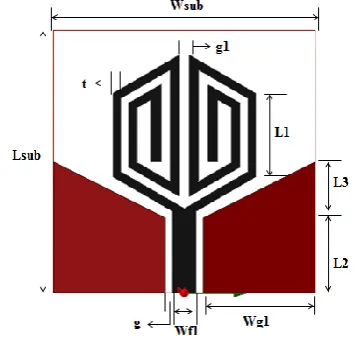
[image:2.595.357.497.50.194.2]A triple frequency CPW feed modified hexagonal patch antenna is designed for multiband applications. The proposed tribands antenna has been implemented in three steps. The hexagon shape modified into U-shape with long stubs and it will consider as first iteration as shown in figure 2(a). Figure 2(b) & 2(c) shows the second and third iteration structures. Finally, antenna – 3 resonates at three different resonant frequencies. All the simulated resulst are depicted in section – V. The design parameters of designed antennas are represented in figure 2(c). All these parameters are described in table I.
Table I: Parameters depicted on figure 2 (All the units are in mm)
Lsub Wsub Lg L Wg Wf L1
28 28 7 2 11.5 3 8.8
g g1 t Wf2 Wg1 L2 L3
1 1 0.85 2.5 12 8 6
(a) Antenna – 1 (b) Antenna – 2
[image:2.595.77.289.50.247.2](c) Antenna – 3
Fig 2: Implementation of triband antenna IV. PENTABANDANTENNADESIGN
METHODOLOGY
With slight modifications in the tribands antenna design, this antenna resonates at five frequencies with good radiation pattern characteristics. The proposed pentaband antenna is shown in figure 3. Parameters mentioned on design are shown in table I.
Fig 3: Pentaband antenna design top view V. SIMULATIONRESULTSANDDISCUSSION A. UWB antenna results
[image:2.595.342.522.314.487.2]Figure 4 shows the reflection coefficient characteristics of hexagon shaped patch antenna. This antenna covers a wide range of bandwidth over 3.15-10.75GHz with good reflection coefficient. The voltage standing wave ratio (VSWR) plot for this corresponding design is shown in figure 5. Figure 6 & 7 shows the far field reports of hexagon antenna design.
[image:2.595.45.293.508.734.2]Fig 5: VSWR characteristics of UWB antenna design
Fig 6: 3D gain plot
Fig 7: radiation pattern (Red – E - plane & black – H-plane)
B. Triband antenna results
Figure 8 shows the return loss characteristics comparison between antenna – 1, 2 & 3. Finally, this antenna -3 resonates at three frequencies such as 1.36GHz, 5.74GHz and 8.80GHz with impedance bandwidths are 20MHz, 1.68GHz, 570MHz respectively.
Fig 8: Return loss characteristics comparison between antenna – 1, 2 & 3
C. Pentaband antenna results
By changing the slight modifications in antenna – 3, a new structure has been introduced. It resonates at five frequencies such as 2.38GHz, 3.64GHz, 6.76GHz, 7.36GHz and 8.98GHz with their corresponding bandwidths are 200MHz, 70MHz, 270MHz, 520MHz and 420MHz respectively. The simulated reflection coefficient characteristics are shown in figure 9 and VSWR is shown in figure 10.
Fig 10: Return loss characteristics of pentaband antenna
Fig 11: VSWR characteristics of pentaband antenna The gains at their operated frequencies are 1.77dB, 2.45dB, 3.53dB, 4.54dB and 2.28dB respectively. The radiation patterns at these resultant frequencies are shown in figure 12.
a) 2.38GHz b) 3.64GHz c) 6.76GHz
d) 7.36GHz e) 8.98GHz
Fig 12: Graphical representation of E- & H- field characteristics of pentaband antenna
(Red- E-plane & Black –H-plane)
a) 2.38GHz b) 3.64GHz
c) 6.76GHz d) 7.36GHz
[image:4.595.58.277.50.425.2]e) 8.98GHz
Fig 13: Magnitude current distribution of pentaband antenna at their resonant frequencies.
VI. DESIGNSUMMARY
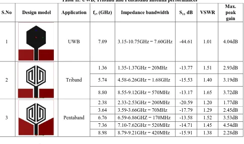
All these designed antennas performances are presented in table II.
VII. CONCLUSION
This paper stated with UWB application obtained from hexagonal shaped microstrip patch antenna with CPW feeding on FR4 epoxy material, which covers 3.15-10.75GHz range suitable for S-, C- and X- band wireless applications. Later by applying several iterations on hexagon, it results triple resonances at 1.36GHz, 5.74GHz and 8.50GHz with good radiation characteristics. Finally, multiple resonances obtained for pentaband antenna at 2.38GHz, 3.64GHz, 6.76GHz, 7.36GHz and 8.98GHz with maximum peak gains are 1.77dB, 2.45db, 3.53dB, 4.54dB and 2.28dB respectively. This proposed antenna has impedance matching and radiation efficiency. This antenna is suitable for GSM1800, Bluetooth, WiFi, WiMAX and Satellite applications.
REFERENCES
1.Elsheakh, D., & Abdallah, E. (2018). Ultra-wide-bandwidth (UWB)
microstrip monopole antenna using split ring resonator (SRR)
structure. International Journal of Microwave and Wireless
Technologies,10(1), 123-132. doi:10.1017/S1759078717001131
2.Anders G. Derneryd, “Microstrip Array Antenna”, IEEE Explore, 19th
March 2007. 10.1109/EUMA.1976.332297
3.Tale Saeidi, Idris Ismail, Wong Peng Wen, Adam R. H. Alhawari, and Ahmad Mohammadi, “Ultra-Wideband Antennas for Wireless Communication Applications,” International Journal of Antennas and
Propagation, vol. 2019, Article ID 7918765, 25 pages,
2019. https://doi.org/10.1155/2019/7918765.
4.Zhangfang Hu, Yinping Hu*, Yuan Luo, and Wei Xin, “A Novel
Rectangle Tree Fractal UWB Antenna with Dual Band-Notched Characteristics”, Progress In Electromagnetics Research C, Vol. 68, 21–30, 2016
5.Zhu, Shaozhen, Keneth L. Ford, Alan Tennant and R. J. Langley. “Small
antenna over AMC surface with/out vias.” 2012 6th European
Conference on Antennas and Propagation (EUCAP) (2012): 2712-2715.
6.Anju A Chandran , Shiney Thankachan, “Triple Frequency Notch in
UWB Antenna with Single Ring SRR loading”, 6th International Conference On Advances In Computing & Communications, ICACC 2016, 6-8 September 2016, Cochin, India
7.J. Wang, S. Qu, J. Zhang, H. Ma, Y. Yang, C. Gu, and X. Wu., “A
Tunable Left-Handed Metamaterial based on Modified
Broadside-Coupled Split-Ring Resonators”, Progress In
Electromagnetics Research Letters, Vol. 6, 35–45, 2009
8.B. Premalatha1, M. V. S. Prasad and M. B. R. Murthy, “Compact
Hexagonal Monopole Antenna”, Indian Journal of Science and Technology, Vol 10(19), DOI: 10.17485/ijst/2017/v10i19/91388, May 2017.
9. Sourabh Bisht, Shweta Saini, Dr Ved Prakash, Bhaskar Nautiyal, “Study
The Various Feeding Techniques of Microstrip Antenna Using Design and Simulation Using CST Microwave Studio”, International Journal of Emerging Technology and Advanced Engineering (ISSN 2250-2459, ISO 9001:2008 Certified Journal, Volume 4, Issue 9, September 2014)
10.Sompop Pimpol, “Design and experimental wideband hexagonal slot
array patch antenna”, IEEE Explore 12th July 2011.
DOI: 10.1109/ECTICON.2011.5947806
11.Ch.Murali Krishna, P.James Vijay, “Design and Analysis of Integrated PIFA for Wireless Applications”, International Journal Of Research In Electronics And Computer Engineering, Vol. 6 Issue 3, July - September 2018
12.P. Krishna Kanth Varma, Ch. Murali Krishna, G. Santhi Ratna Priyanka,
“Performance Improvement of Sri Yantra Shaped Multiband Antenna with Defected Ground Structure”, International Journal of Engineering & Technology, 7 (3.31) (2017) 40-44
13.Ch Murali Krishna, P James Vijay, M Ravi, “Compact Log Periodic
Dipole Array Antenna For Multiband Applications Using S-Fractal Curve”, International Journal of Research in Engineering and Technology, Volume: 07 Issue: 06 June-2018
14.AmandeepSingha, SurinderSinghb, “A modified coaxial probe-fed
Sierpinski fractal wideband and highgain antenna”, International Journal
of Electronics and Communications, 2015
http://dx.doi.org/10.1016/j.aeue.2015.02.001
15.Yun Jing Zhang, Dan Wang, Li Zhang, and Mei Song Tong, “A Modified
Planar Inverted-F Antenna with Triple-Band for Wi-Fi and LTE Applications”, Progress In Electromagnetics Research M, Vol. 73, 173–181, 2018
16.Garima, D. Bhatnagar, J.S. Saini and V.K. Saxen, “Modified circular patch antenna with key shape slot for wireless communication systems”, International Journal of Microwave and Optical Technology, Vol.5, No.6, November 2010
17.Md Shahriar Istiak, Sunny & Rahman, Iftekhar & Aftab, Syed & Muhammad, Shaikh & Islam, Md. Ashraful. (2017). Design and Performance Analysis of a Log Periodic Dipole Antenna with a Frequency Range of 1350 to 2690 MHz. 4. 6-12.
Table II: UWB, Triband and Pentaband antenna performances
S.No Design model Application fr, (GHz) Impedance bandwidth S11 dB VSWR
Max. peak gain
1 UWB 7.09 3.15-10.75GHz = 7.60GHz -44.61 1.01 4.04dB
2 Triband
1.36 1.35-1.37GHz = 20MHz -13.77 1.51 2.93dB
5.74 4.58-6.26GHz = 1.68GHz -15.53 1.40 3.19dB
8.80 8.55-9.12GHz = 570MHz -13.17 1.65 3.72dB
3 Pentaband
2.38 2.33-2.53GHz = 200MHz -20.59 1.20 1.77dB
3.64 3.59-3.66GHz = 70MHz -17.79 1.29 2.45dB
6.76 6.59-6.86GHZ = 170MHz -13.58 1.52 3.53dB
7.36 7.10-7.62GHz = 520MHz -14.71 1.45 4.54dB
8.98 8.79-9.21GHz = 420MHz -15.91 1.38 2.28dB
AUTHORSPROFILE
Ch.Murali Krishna is presently working as an assistant professor in the department of ECE, Ramachandra College of Engineering, Eluru. He is currently working on Micro strip patch antennas design for wireless communications with various feeding techniques. Present focusing on optimization using artificial neural intelligence techniques.
P James Vijay is presently working as an assistant professor in the department of ECE, S.R.K.R. Engineering College, Bhimavaram. He is currently working on practical antennas design and Image processing.
P.Satya Sai pursuing B.Tech in ECE, Ramachandra college of Engineering in Eluru, Andhra Pradesh. Her
areas of interests are Antenna designing and
communications.