International Journal of Innovative Technology and Exploring Engineering (IJITEE) ISSN: 2278-3075, Volume-9 Issue-2, December 2019
Abstract: A typical magnetic resonance based wireless power transfer (WPT) system comprises a transmitter coil and an embedded receiver coil used for wireless charging of the electrical and electronics devices. It has been investigated that the coil structure influence the power transfer efficiency of the wireless charging system .The investigations have been carried out in order to determine a suitable coil type and geometry so as to achieve higher efficiency of a wireless power transfer system. The present investigation will afford the design strategy for an efficient wireless charging system .
Keywords: Charging Coil Structure, Magnetic resonance, Wireless charging, Power transfer efficiency
I. INTRODUCTION
During this time of an Earth-wide temperature boost because of Carbon Dioxide (CO2) discharges, regional authorities everywhere throughout the world are scrambling today to execute arrangements so as to decrease CO2 outflows from their private and public vehicles [1]. Thus, there is much interest has been laid by the transportation industry towards electric vehicles to minimize the carbon emission [2-3]. Although the plug in vehicle charging system is adopted for charging vehicle but to overcome the associated difficulties as well as to improve the convenience and usability of EVs, there is a need to develop wireless power transfer system (WPTS) for charging of EVs. Many research reports [4-8] revealed that the non radiative magnetically coupled WPTS, which illustrated the possibility to transmit power more efficiently for EV charging than the conventional inductive systems. The idea of magnetic resonance based wireless charging for EVs is recently getting much attention by industry as well as academic groups [9-12]. Nonetheless, for designing practical EV charging setup, it is not adequate to just substantiate the power transmission between the transmitting and receiving charging coils but utmost needed to surmount the associated key issues that influence the power transfer efficiency. Hence, simulation and experimental investigation have been done in the present work to delineate the design guidelines for wireless EV charging.
II. Study of Different Coil Structure
The open planar spiral coil with concentric spirals as shown in Fig.1. The outer diameter is 30 cm and the
Revised Manuscript Received on December 05, 2019. * Correspondence Author
Praveen P Nayak, Associate prof in ECE, Siksha O Anusandhan University, Bhubaneswar, Odisha, India([email protected])
[image:1.595.306.558.230.319.2]innermost diameter is 24.35cm. The wire diameter used is 2mm, the spiral spacing used is 5mm and the number of turns used is 5.
Fig.1 open planar spiral coil with concentric spirals
The simulation is done using CST. Frequency domain solver of the CST Microwave studio is used for the simulation. Frequency domain solver is used since the dimensions of the coil are very small compared with the wavelength of the signal frequency. The simulated results are shown in Fig.2
Fig.2 simulation result of open planar spiral coil with concentric spirals using CST
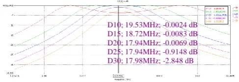
The simulation is carried out for different spacing between the transmitter and receiver coil. The spacing is varied from 10cm to 30cm. The interval is 5cm. The efficiency is calculated based on the square of the magnitude of S21. The efficiencies obtained for different spacing are as follows.
Table 1
Distance
(cm)
Frequency (MHz)
S21 (dB)
Efficiency (%)
1 10 19.53 -0.0024 99.8
2 15 18.72 -0.0083 96.2
3 20 17.94 -0.0069 99.7
4 25 17.94 -0.9148 65.6
5 30 17.98 -2.848 26.9
The results of the simulation are presented in the Table 1. This structure can provide very good efficiency for distances up to 20cm between the transmitter and receiver coils. But beyond 20cm, the efficiency falls
drastically. Another thing to be
Effect of Coil Structure on the Efficiency of
Wireless Power Transfer System
Jagadish C Padhi, Sushree Sangita BiswalDurga P Kar, Praveen P Nayak, and Satyanarayan
Bhuyan
[image:1.595.317.561.419.503.2]noted is that though very high efficiency is achievable for distances up to 20cm, the frequency at which that efficiency is achievable is different for different distances. For example, at the distance of 10cm, 99.8% efficiency is obtained at 19.53MHz whereas for 20cm distance, the frequency shifts to 18.72MHz for 96.2% efficiency.
For implementing this coil structure foe wireless charging, it is necessary to have a frequency agile feedback system so as the tune the operating frequency of the system for different distances between the coils. The thickness of this coil structure is very small since the spiral is planar. So this type of an coil structure can be easily mounted on the electric vehicle.
The open helix coil structure is one in which the signal is fed to one port of the helix and the other port is an open port. The number of turns used is 5. The diameter of the wire used for the construction of the helix is 2mm. The diameter ratio between the first turn and the last turn is one meaning that all the turns have the same diameter. The diameter of the helix is 30cm.The pitch or the spacing between the turns is 5mm. The helical coil is shown in Fig.3
Fig.3 helical coil
The overall height of each helix is about 2.5cm. Frequency domain solver is used since the dimensions of the coil are very small compared with the wavelength of the signal frequency. The results of the simulation are shown in Fig.4.
Fig.4 simulation of helical coil
[image:2.595.314.537.248.339.2]Identical helical coils are used as transmitter and receiver coils. The simulation is used to calculate S21 to provide a measure of how much power is transferred from the transmitter coil to the receiver coil. The spacing between the coils is varied from 10cm to 30cm and S21 is calculated for each of the spacing. Overall power transfer efficiency is calculated from the simulated S21 and is presented in the Table 2 shown below.
Table 2
Distance (cm)
Frequency (MHz)
S21 (dB)
Efficiency (%)
1 10 13.11 -6.1 6.03
2 15 14.65 -1.65 46.77
3 20 14.53 -3.77 17.62
4 25 14.32 -2.62 29.92
5 30 13.85 -1.33 54.2
The results obtained from the simulation as shown here is not encouraging. The efficiency obtained for various spacing is far too low compared to the objective, the maximum being
54.2% at a distance of 30 cm. From the simulation is can be observed that each graph has two peaks. This is caused by the coupling between the two helical coils. As the spacing increases, the coupling becomes lower. So we see that generally the efficiency is better as the spacing is larger
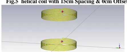
In order to improve the efficiency of the helical coil, a new type of feed structure for the helical coil was designed. This new feed structure is an offset feed structure. The diameter of the wire used for constructing the helix is 2mm. All the turns have the same diameter and the transmitter and receiver coils are identical. The pitch is 8mm. The helical coil with the modified feed structure is shown in Fig.5 . The helical coil used in this schematic has 6 turns. For this simulation the diameter of the coil is made variable. The simulation is done at two fixed distances i.e. 15cm and 25cm. The idea is to determine the most suitable diameter for the coils
Fig.5 helical coil with 15cm Spacing & 0cm Offset
The result of the simulation is shown in Fig.6 . In this simulation the coils are placed vertically without any offset distance between them. It is seen that for different diameters, the frequency for maximum power transfer is different. S21 for each of the diameters are also shown. The results are presented in Table 3
[image:2.595.50.290.307.399.2]Fig.6 simulation for a fixed spacing of 15cm between the coils and for various coil diameters
Table 3
Diameter
(cm)
Frequency (MHz)
S21 (dB)
Efficiency (%)
1 25 17.442 -0.198 91.28
2 30 14.137 -0.234 89.76
3 35 11.842 -0.277 88.02
4 40 9.042 -0.293 87.36
5 45 7.852 -0.292 87.42
6 50 6.884 -0.319 86.31
[image:2.595.61.298.454.545.2]International Journal of Innovative Technology and Exploring Engineering (IJITEE) ISSN: 2278-3075, Volume-9 Issue-2, December 2019
Fig.7 helical coil with 15cm Spacing & 15cm Offset
[image:3.595.312.554.52.272.2]The result of the simulation for various diameters is shown in Fig.8
Fig.8 simulation for helical coil with 15cm Spacing & 15cm Offset with various diameters
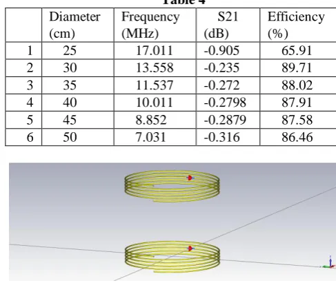
[image:3.595.52.296.142.295.2]The power transfer efficiency is calculated from the results of the simulation for various coil diameters and is presented in Table 4.
Table 4
Diameter (cm)
Frequency (MHz)
S21 (dB)
Efficiency (%)
1 25 17.011 -0.905 65.91
2 30 13.558 -0.235 89.71
3 35 11.537 -0.272 88.02
4 40 10.011 -0.2798 87.91
5 45 8.852 -0.2879 87.58
6 50 7.031 -0.316 86.46
Fig.9 helical coil 15cm Spacing & 0cm Offset
[image:3.595.52.296.338.545.2]The helical coil shown in Fig. 9 has 5 turns. For this simulation also the diameter of the coil is made variable. The simulation is done at two fixed distances i.e. 15cm and 25cm.
Fig.10 simulated result for helical coil 15cm Spacing & 0cm Offset
The efficiencies calculated from the readings obtained from the simulation for various coil diameters are shown in Table 5
Table 5
Diameter (cm)
Frequency (MHz)
S21 (dB)
Efficiency (%)
1 25 21.44 -0.1496 93.34
2 30 17.53 -0.1713 92.41
3 35 14.85 -0.1877 91.72
4 40 11.39 -0.1999 91.21
5 45 9.847 -0.2226 90.12
6 50 8.6 -0.2334 89.81
Fig.11 helical coil 15cm Spacing & 15cm Offset
The simulation results for a spacing of 15cm and an offset of 15 cm is shown in Fig 12.
Fig.12 simulated result for helical coil 15cm Spacing & 15cm Offset
The efficiencies calculated from the readings obtained from the simulation for various coil diameters are shown in Table 6
Table 6
Diameter (cm)
Frequency (MHz)
S21 (dB)
Efficiency (%)
1 25 21.12 -1.62 47.42
2 30 16.91 -0.3407 85.48
3 35 14.378 -0.1862 91.78
4 40 12.467 -0.1962 91.36
5 45 10.976 -0.2164 90.51
6 50 8.79 -0.2334 89.81
[image:3.595.61.295.607.687.2]From these results, it is seen that a coil with 5 turns and having a coil diameter of 35, 40 or 45cm can meet the power transfer efficiency requirement for 15cm spacing and 15cm offsetThe performance of the same set of coils is evaluated at a spacing of 25cm. The simulation result for 25cm spacing without any offset is presented in Fig 13. The efficiencies calculated from the simulation results presented in Fig 13 for various coil diameters are shown in Table 7.
[image:3.595.320.555.667.723.2]Table 7
Diameter (cm)
Frequency (MHz)
S21 (dB)
Efficiency (%)
1 25 21.108 -2.61 30.06
2 30 16.911 -1.007 62.89
3 35 14.161 -0.3039 86.94
4 40 12.163 -0.2032 91.07
5 45 10.238 -0.2173 90.47
6 50 8.95 -0.234 89.78
Fig. 14 simulated result for helical coil 25cm Spacing & 15 cm Offset
The efficiencies calculated from the simulation results presented in Fig 14 for various coil diameters are shown in Table 8
Table 8
Diameter (cm)
Frequency (MHz)
S21 (dB)
Efficiency (%)
1 25 21.137 -5.48 8.01
2 30 16.925 -2.81 27.41
3 35 14.175 -1.188 57.86
4 40 12.047 -0.422 82.34
5 45 10.484 -0.217 90.49
6 50 9.065 -0.2383 89.61
From the simulations it is seen that an coil having a diameter of 45 cm can meet the range and offset requirements.
Simulation using the helical coil with 5 turns gave better results compared to the helical coil with 6 turns, another set of simulations are carried out with helical coil having 4 turns. The simulation is done at two fixed distances i.e. 15cm and 25cm and for offsets of 0cm and 15cm.
Fig.15 helical coil with 4 turns 15cm Spacing & 0cm Offset
The simulation is carried out for various diameters of the coils ranging from 25cm to 50cm. The simulation results are presented in Fig 16.
Fig 16 simulation helical coil with 4 turns 15cm Spacing & 0cm Offset
The efficiencies calculated from the simulation results presented in Fig 16 for various coil diameters are shown in Table 9.
Table 9.
Diameter (cm)
Frequency (MHz)
S21 (dB)
Efficiency (%)
1 25 25.609 -0.2916 87.43
2 30 21.053 -0.1388 93.8
3 35 17.977 -1.1413 93.7
4 40 14.046 -0.1529 93.2
5 45 12.122 -0.172 92.38
6 50 10.592 -0.179 92.08
Fig 17 helical coil with 4 turns 15cm Spacing & 15cm Offset
The simulation results for a spacing of 15cm and an offset of 15 cm as shown in Fig 18.
Fig 18. simulation results for a spacing of 15cm and an offset of 15 cm
The efficiencies calculated from the simulation results presented in Fig 18 for various coil diameters are shown in Table 10.
Table 10.
Diameter (cm)
Frequency (MHz)
S21 (dB)
Efficiency (%)
1 25 25.718 -3.266 22.22
2 30 20.675 -1.144 59.04
3 35 17.186 -55.74 71.12
4 40 14.97 -0.1529 93.2
5 45 12.44 -0.166 92.64
6 50 11.878 -0.1798 92.05
International Journal of Innovative Technology and Exploring Engineering (IJITEE) ISSN: 2278-3075, Volume-9 Issue-2, December 2019
Fig 19 simulation results for a spacing of 25cm and an offset of 0 cm
[image:5.595.61.297.52.136.2]The efficiencies calculated from the simulation results presented in Fig 19 for various coil diameters are shown in Table 11. The horizontal offset is increased to 15cm for the simulation. The simulated results are shown in Fig 20
Table 11
Diameter (cm)
Frequency (MHz)
S21 (dB)
Efficienc y (%)
1 25 25.707 -4.43 13
2 30 20.674 -2.29 34.83
3 35 17.27 -1.03 62.23
4 40 14.737 -0.404 83.02
5 45 12.845 -0.189 91.66
6 50 11.118 -0.181 92
Fig 20 simulation results for a spacing of 25cm and an offset of 15 cm
[image:5.595.55.292.229.429.2]The efficiencies calculated from the simulation results presented in Fig 20 for various coil diameters are shown in Table 12
Table 12
Diameter (cm)
Frequency (MHz)
S21 (dB)
Efficiency (%)
1 25 25.74 -7.79 2.77
2 30 20.641 -4.69 11.53
3 35 17.286 -2.59 30.34
4 40 14.704 -1.29 55.2
5 45 12.813 -0.556 77.41
6 50 11.316 -0.2468 89.26
The helical coil with 4 turns shows good performance in terms of efficiency when the spacing between the coils is 15cm. But when the spacing is increased to 25cm, the performance becomes worse than that of the helical coil with 5 turns. From this study of the helical coil with offset feed, it is clear that the coil having 5 turns with a diameter of 45 cm can meet the performance objective of the system
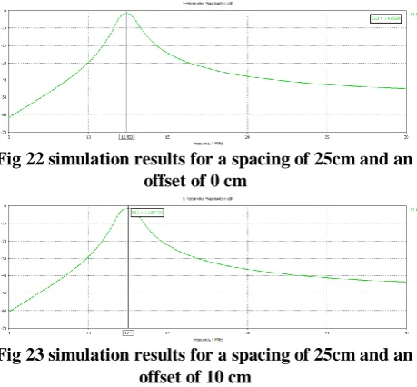
The performance of the helical coil system with modified feed structure when the transmitter coil diameter is larger than the receiver coil diameter. In this case even when there is a large offset between the centres of the coil, the position of the receiver coil lies with in the coverage area of the transmitter coil. The schematic diagram of such a configuration is shown in Fig 21.
Fig 21 transmitter coil diameter is larger than the receiver coil diameter
[image:5.595.319.549.281.494.2]The receive coil has 6 turns and the diameter is 30cm and the transmit coil has 4 turns and the diameter is 50cm. The transmitter and the receiver coil coils have different number of turns since the diameters are different. This is required to ensure that both resonate at the same frequency. The spacing between the coils is 25 cm. Simulation is done for two offset positions, one without any offset and another with 10cm offset. The result of the simulation with offset is given is Fig. 22 and the one without offset is given in Fig. 23
Fig 22 simulation results for a spacing of 25cm and an offset of 0 cm
Fig 23 simulation results for a spacing of 25cm and an offset of 10 cm
From the results it is seen that the overall efficiency of the system is much lower than the earlier simulations. But it can be seen that the variation in S21 is not that significant
III. CONCLUSION
The present investigation represents that the planar spiral coil structure provides very good efficiency for distances up to 20cm between the transmitter and receiver coils. The thickness of this antenna structure is very small since the spiral is planar. So this type of coil structure can be easily mounted on the electric vehicle. In order to improve the efficiency of the helical antenna, a new type of feed structure for the helical antenna is designed. It can be seen from the results that the new feed structure provides a much higher efficiency. The effect of different coil structure on the power transfer efficiency results provides the design guidelines for an EV charging system.
REFERENCES
1. D. P. Kar, P. P. Nayak, S. Bhuyan, S. K. Panda, “Automatic frequency tuning wireless charging system for enhancement of efficiency”, Electronics Letters, vol. 50, no. 24,
[image:5.595.55.296.509.617.2]2. Li S, Mi CC. Wireless power transfer for electric vehicle applications. IEEE J Emerg Sel Top Power Electron 2005;3:4–17
3. A. Kurs, A. Karalis, R. Moffatt, J. D. Joannopoulos, P. Fisher, and M. Soljacic, "Wireless power transfer via strongly Coupled magnetic resonances," Science,vol. 317,no. 5834,pp.83–86,2007.
4. D. P. Kar, S.S. Biswal, P.K. Sahoo, P. P. Nayak, S. Bhuyan, “Selection of maximum power transfer region for resonant inductively coupled wireless charging system,” AEU-International journal of Electronics and Communications, vol. 84, pp.84-92, 2018.
5. Z. N. Low, R. A. Chinga, R. Tseng, and J. Lin, "Design and test of a high-power high-efficiency loosely coupled planar wireless power transfer system," IEEE Transactions on Industrial Electronics, vol. 56, no. 5, pp. 1801–1812, 2009.
6. D. P. Kar, P. P. Nayak, S. Bhuyan, D. Mishra, “Bi-directional magnetic resonance based wireless power transfer for electronic devices”, Applied Physics Letters vol. 107, no. 13, pp. 133901, 2015
7. A. P. Sample, D. A. Meyer, and J. R. Smith, "Analysis, experimental results, and range adaptation of magnetically coupled resonators for wireless power transfer," IEEE Transactions on Industrial Electronics, vol. 58, no. 2, pp. 544–554, 2011.
8. B.Wang,K.Teo,T.Nishino,W.Yerazunis,J.Barnwell,andJ.Zhang,“Expe riments on wireless power transfer with metamaterials,” Appl. Phys. Lett., vol. 98, pp. 254101–254103, Jun. 2011.
9. S. Sahany, S.S. Biswal, D.P. Kar, P.K. Sahoo, S. Bhuyan, “Impact of functioning parameters on the wireless power transfer system used for electric vehicle charging,” Progress in Electromagnetic Research, vol. 79, pp.187-197, 2019.
10. B. L. Cannon, J. F. Hoburg, D. D. Stancil, and S. C. Goldstein, “Magnetic resonant coupling as a potential means for wireless power transfer to multiple small receivers,” IEEE Trans. Power Electron., vol. 24, no.7, pp. 1819–1825, Jul. 2009.
11. A. K. RamRakhyani, S. Mirabbasi, and M. Chiao, “Design and optimization of resonance-based efficient wireless power delivery systems for biomedical implants,” IEEE Trans. Biomed. Circuits Syst.,vol.5, no.1,pp.48–63,Feb.2011.
12. A.P.Sample,D.A.Meyer, and J.R.Smith, “Analysis experimental results, and range adaptation of magnetically coupled resonators for wireless power transfer,” IEEE Trans. Ind. Electron., vol. 58, no. 2, pp. 544–554, Feb. 2011.
AUTHORS PROFILE
Mr. Jagadish Chandra Padhi received M.Tech degree in Microelectronics from Siksha O Anusandhan University, Bhubaneswar, Odisha in 2014 and Perusing his PhD in the areas Wireless power Transfer
Dr.Durga Prasanna Kar received PhD degree from Siksha O Anusandhan University, Bhubaneswar, Odisha in 2017. His research interest includes Wireless power transfer and electromagnetism.
Dr. Praveen Priyaranjan Nayak currently Associate Professor from Siksha O Anusandhan University, Bhubaneswar, Odisha. He was awarded PhD. in the year 2017 from Siksha O Anusandhan University, Bhubaneswar, Odisha. His research interest includes Wireless power transfer and electronic devices
Dr.Satyanarayan Bhuyan is currently Associate Professor from Siksha O Anusandhan University, Bhubaneswar, Odisha. His present research interests include wireless drive of piezoelectric components, wireless charging for electric vehicles.