Rochester Institute of Technology
RIT Scholar Works
Theses
Thesis/Dissertation Collections
2008
Imaging the airways
Betsy Skrip
Follow this and additional works at:
http://scholarworks.rit.edu/theses
This Thesis is brought to you for free and open access by the Thesis/Dissertation Collections at RIT Scholar Works. It has been accepted for inclusion in Theses by an authorized administrator of RIT Scholar Works. For more information, please [email protected].
Recommended Citation
IMAGING THE AIRWAYS
ROCHESTER INSTITUTE OF TECHNOLOGY
A Thesis Submitted to the Faculty of
The College of Imaging Arts and Sciences
In Candidacy for the Degree of
MASTER OF FINE ARTS
ETSY SKRIP
Medical Illustration
3D Modeling of a Complete Respiratory Airway for Use in
Computational Flow Dynamics Studies of Particle Deposition in the Lungs Creation of an Educational Animation about the Respiratory System for Use in the Human Visualization Project and CollaboRITorium
INTRODUCTION
The IMAGING THE AIRWAYS proj-ect consists of two main parts, with the first part further separated into three sections.
Part I. 3D Modeling of a Com-plete Respiratory Airway for Use in Computational Flow Dynamics
ABSTRACT
The IMAGING THE AIRWAYS thesis project is a multidiscipline and multimedia endeavor consisting of two main parts: I. 3D Modeling of a Complete Respiratory Airway for Use in Computational Flow Dynamics Studies of Particle Deposition in the Lungs and II. Creation of an Educational Animation about the Respiratory System for Use in RIT’s Human Visualization Project and CollaboRITorium.
Part I involved collaboration with RIT’s Mechanical Engineering Department to construct a 3D model of one complete respiratory pathway, from the oral cavity to the site of gas exchange between the lungs and the blood. The project is a continuation of thesis work completed by Jackie Russo, MS Mechanical Engineering, Class of 2007 and Jessica Weisman, MFA Medical Illustration, Class of 2007. Russo and Weisman constructed a model of the upper respiratory tract, from the oral cavity to generation 5 (as defined by Des Jardins, 2007). Weisman also constructed a model of a respiratory acinus (generation 20-28).
Part I of the IMAGING THE AIRWAYS thesis project involved creating a Maya model of generations 6-19 to bridge the two existing models and creating a Maya model of the respiratory membrane to study nanoparticle translocation from the lungs to the blood. Part I of the project also involved creating promotional materials that were featured in the March 17-April 9, 2008 thesis show and at the 2008 Imagine RIT Innovation and Creativity Festival. The promotional materials consist of a 35” x 43” poster, a postcard, a website, and a one-minute promotional video.
Part II of the project involved creating a 5-minute animation about the respiratory system for use by RIT’s Human Visualization Project (HVP) and CollaboRITorium, as well as an HVP website.
I M A G I N G T H E A I R W A Y S
3D Modeling of a Complete Respiratory Airway for Use in Computational Flow Dynamics Studies of Particle Deposition in the LungsCreation of an Educational Animation about the Respiratory System for Use in the Human Visualization Project and CollaboRITorium
Betsy Skrip Medical Illustration, Rochester Institute of Technology
CONTENTS
INTRODUCTION
1
Part I.I Bronchi/Bronchiole Model ORIGINAL THESIS STATEMENT 2
BACKGROUND 2
THE BODY OF WORK 4
CONCLUSIONS 8
Part I.2 Respiratory Membrane ORIGINAL THESIS STATEMENT 10
BACKGROUND 10
THE BODY OF WORK 12
CONCLUSIONS 16
Part I.3 Promotional Materials ORIGINAL THESIS STATEMENT 17
BACKGROUND 17
THE BODY OF WORK 17
CONCLUSIONS 38
Part II Respiratory System Animation ORIGINAL THESIS STATEMENT 39
BACKGROUND 39
THE BODY OF WORK 40
CONCLUSIONS 46
OVERALL CONCLUSIONS
50
ACKNOWLEDGEMENTS
50
REFERENCES
50
Studies of Particle Deposition in the Lungs
The main thesis project, conducted for RIT’s Mechanical Engineering Depart-ment under the direction of thesis su-pervisors Dr. Risa Robinson, Jim Perkins, and Glen Hintz, as well as professors Nancy Ciolek and Ann Pearlman.
Part I.I Bronchi/Bronchiole Model Modeling of the respiratory path be-tween the upper tract and a respira-tory acinus.
IMAGING THE AIRWAYS
Par t I.I ORIGINAL THESIS STATEMENT, BACKGROUNDel will then be meshed to the two existing models to form one com-plete model.
The complete model will be im-ported into two computational flow dynamic engineering software pro-grams (Fluent and Comsol) in order to study particle flow and deposi-tion in the lungs.
Effectiveness and accuracy of the model will be evaluated based on comparisons to published data, such as that derived from biological specimens.
Current methods for creating an ac-curate model of the respiratory air-ways include scanning and creating casts from cadavers; however, these methods create only a static model. The main contribution of working in Maya is the ability to generate a modifiable model in which research-ers can vary different parametresearch-ers of the tract’s morphometry and exam-ine the effects of those variations.
The ability to alter different param-eters of an airway model will en-hance research to better define the mechanics of breathing and changes in particle flow and deposition among different disease states, such as asthma and emphysema.
Maya also allows for the creation of a more organically shaped model than current engineering CAD (Com-puter-Aided Design) programs.
BACKGROUND
Over several years, Dr. Risa Robin-son in RIT’s Mechanical Engineering Department and Dr. Richard Doo-little in RIT’s Allied Health Sciences Department have spearheaded stu-dent research to better understand the mechanics of breathing.
In 2006, two graduate students–
Jackie Russo (MS Mechanical Engi-neering, Class of 2007) and Jessica Weisman (MFA Medical Illustration, Class of 2007)–designed their thesis projects to model parts of the re-spiratory system using 3D comput-er software. The models wcomput-ere then analyzed using engineering compu-tational flow dynamics software in order to study fluid flow and par-ticle deposition in the respiratory system.
Russo and Weisman produced the following models:
1. A model of the upper respira-tory tract
Created by Russo (2007) and Weis-man (2007)
This model consists of three mod-els, each created using different methods: (1) the oral cavity, (2) the oropharynx, laryngeopharynx, and larynx, and (3) the trachea through bronchi generation 5.
2. A model of a respiratory aci-nus
Created by Weisman (2007)
This model was constructed us-ing the same overall methods and consists of generations 20-28 (the respiratory bronchioles, alveolar ducts, and alveolar sacs).
Several systems exist for number-ing the structures of the respira-tory tree. Differences among these systems result in part because the number of branches beyond the bronchi differ among individuals and among the lungs’ regions. For this project, Des Jardin’s (2007) system was used, in which the structures are numbered as follows:
Generation
Trachea 0
Main stem bronchi 1
Lobar bronchi 2
Segmental bronchi 3 Subsegmental bronchi 4-9 Bronchioles 10-15 order to visualize nanoparticle
trans-port from the lungs into the blood-stream.
Part I.3 Promotional Materials Creation of promotional materials for the project to educate the RIT commu-nity and other interested audiences.
Part II. Creation of an Educational Animation about the Respiratory System for Use in the Human Vi-sualization Project and CollaboRI-Torium
An animation and website created for RIT’s Human Visualization Project and CollaboRITorium under the direction of thesis supervisors, as well as Dr. Rich-ard Doolittle, Shaun Foster, and Dr. Jake Noel-Storr.
Part I.I Bronchi/Bronchiole Model Modeling of the respiratory path be-tween the upper tract and a respira-tory acinus.
ORIGINAL THESIS STATEMENT
The aim of this project is to create a 3D computer-generated model of generations 6-19 of a single respira-tory airway.
The model will bridge existing com-puter-generated models created for use by the Mechanical Engineer-ing Department: models extendEngineer-ing from the oral cavity to generation 5 and a model of a single acinus (gen-erations 20-28).
The end product of this project will be a complete model of a respira-tory airway extending from the oral cavity to the alveoli.
mod-IMAGING THE AIRWAYS
Par t I.I BACKGROUNDTerminal bronchioles 16-19 Respiratory bronchioles 20-23 Alveolar ducts 24-27 Alveolar sacs 28
Generations 0-19 are termed “con-ducting” structures, for they channel air from the mouth and nose to the respiratory acini (as well as in the opposite direction from the acini to the atmosphere). Gas exchange with the blood occurs within the respiratory acini, which each consist of generations 20-28.
Previous Research
In her study, 3D Reconstruction of a Female Lung Using the Visible Human Data Set to Predict Cigarette Smoke Particle Deposition, Russo utilized two upper respiratory models: one with the normal oral cavity model (meant to represent a non-smoker) and one with an oral cavity model in which the casting material was si-phoned through a straw (represent-ing the mouth structure of a smoker at the time of inhalation).
Russo’s procedure for importing the upper respiratory models into the computational flow dynamics software involves three main steps:
1. Importing the original models generated with Maya or 3D Doc-tor into VP-Sculpt for refinement and to combine the separate model components into one model.
2. Importing the VP-Sculpt models into Solid Works in order to con-vert the models from a surface tex-ture to a closed volume. (The sur-face model represents the physical, hollow-interior airway, whereas the closed volume model represents the space inside the airway.)
3. Importing the Solid Works mod-els into computational flow dynam-ics software, such as Gambit, Com-sol, or Fluent.
Using Gambit, Russo calculated a higher air velocity and turbulence in the smoker model. For the particle deposition analysis, Russo injected 0.1-µm (micrometer), 1-µm, 3-µm, 5-µm, 9-µm, and 10-µm particles into both models and calculated deposition in five regions: the oral cavity, throat (i.e, the oropharynx, laryngeopharynx, and larynx), tra-chea, left main bronchi, and right main bronchi.
Russo found that over twice as many particles deposited in the smoker model than in the non-smoker model. Specifically, Russo found that in the smoker model, 45% of all particles deposited in the upper air-way, and in the non-smoker model, only 21% of the particles deposited in the airway.
Russo’s results suggest that the greater air velocity and turbulence in the smoker airway somehow in-fluence particle deposition. Russo hypothesizes that, instead of flow-ing smoothly along the contours of the airway as they would in a non-smoker, the particles in a smoker’s lungs become forcefully propelled into the airway walls, where they then remain.
Russo’s results further suggest that in a smoker, more particles are likely to become trapped in the upper air-way, whereas in a non-smoker, more particles are likely to continue flow-ing to deeper parts of the respira-tory system.
For future research, Russo pro-poses analyzing airflow and particle deposition in those deeper regions, such as in Jessica Weisman’s model of the acinus.
Therefore, the IMAGING THE AIR-WAYS thesis project (specifically, Parts I.1 and I.2) sought to construct models of the deeper regions of the respiratory system and to combine
them with Russo and Weisman’s models. This effort would thereby establish a complete pathway from the oral cavity (the site of gas ex-change between the atmosphere and the lungs) to the respiratory membrane (the site of gas exchange between the lungs and the blood). To the best of our knowledge, such a model has never before been cre-ated.
Completing the pathway would in-volve creating a model of genera-tions 6-19 (to connect the models of the upper respiratory tract and the respiratory acinus) and a model of the respiratory membrane (see Part 1.2).
In order to provide more detail about the overall, collaborative modeling project and to establish a clearer understanding of the meth-ods used to construct Parts I.1 and I.2, the following is a summary of the methods used to create the origi-nal model’s individual parts. (Note: These descriptions, with some varia-tions, also appear on the IMAGING THE AIRWAYS website, http://www. betsyskrip.com/thesis.)
The oral cavity models
Created by Russo (2007)
The oral cavity models were made from a cast of a female student’s mouth. Aquasil Ultra LV Smart Wetting Impression Material was spooned into the student’s mouth and allowed to dry. For the non-smoker model, the mouth was left slightly open and at rest. For the smoker model, the casting mate-rial was also siphoned through a straw placed in the student’s mouth (in order to represent the mouth structure of a smoker at the time of inhalation).
IMAGING THE AIRWAYS
Par t I.I BACKGROUND, THE BODY OF WORKRomer Cimcore Infinite Arm. The arm attachment was used to trace over the surface of the casts and tranferred the data into the com-puter to create a 3D model.
The oropharynx, laryngophar-ynx, and larynx model
Created by Weisman (2007)
The oropharynx, laryngopharynx and larynx model was based on dimensions taken from multiple sagittal and anterior medical pho-tographs of cadavers and a partial cadaver cast of the throat.
The cadaver of an elderly woman was prepared, and silicone rubber was injected through the bottom of the trachea and through the mouth.
The casting material was then al-lowed to dry and removed from the cadaver. Sketches were made and used in Maya to create a 3D model.
The trachea to generation 5 model
Created by Russo (2007)
The trachea/bronchi model was cre-ated using slices of the thoracic cav-ity from the Female Visible Human Project. The slices were imported into 3D Doctor and converted to greyscale in order to increase con-trast among the different anatomical structures. Outlines of the desired structures were then generated by the software based on those con-trasts. Some boundaries were also drawn and refined by hand.
The software rendered a 3D surface model by connecting the defined outlines from all of the segmented images using polygon-based surfac-es. The file was exported as an OBJ and imported into VP-Sculpt for further processing. VP-Sculpt was used to smooth the surface and to trim or delete incomplete branches. Specifically, branches beyond the 5th generation were trimmed off.
The acinus model
Created by Weisman (2007)
Dimensions of the acinus were ob-tained through scanning electron microscopy. The acinus from a male human lung was observed through a scanning electron microscope (SEM), and the dimensions of the respiratory bronchioles, alveolar ducts, and alveolar sacs were mea-sured.
Sketches were made and used in Maya to create a 3D model.
Present Research
As previously mentioned, the upper respiratory model extends to only the 5th generation of branching. Branches beyond the 5th genera-tion were indistinguishable on the Female Visible Human slices. There-fore another method was devised to create a model of generations 6-19 (subsegmental bronchi, bronchioles, and terminal bronchioles) to bridge the models of the upper respiratory tract and the respiratory acinus.
Without access to a human cast, the best solution was to use data published by Horsfield et al.(1971). The researchers created a resin cast of the respiratory tree from a male cadaver and measured the lengths, diameters, and angles of branching for all structures down to 0.7 mm in diameter. They then broke off a single branch to measure structures smaller than 0.7 mm in diameter.
For our model, the data set chosen was for the pathway corresponding to what Horsfield et al. define as the lower posterior lobe of the left lung. The left lung was chosen arbitrarily; however, the pathway to the lower posterior lobe was selected specifi-cally because of its length. From the oral cavity, air must flow the great-est distance to reach the lower pos-terior lobe than to any other lobe. Therefore, our model would allow for analysis of airflow and particle
deposition at the farthest regions of the respiratory system.
A complete pathway model in gen-eral would also allow for the deter-mination of the transition point at which particles stop moving by con-vection and begin moving by diffu-sion. Broadly, this phenomenon re-sults from the mixing of inhaled air and residual air (i.e., air that remains in the lungs even after a forceful ex-halation). It is suspected that each lobe has its own transition point; therefore, our model would en-able determination of the transition point in the lower posterior lobe of the left lung.
THE BODY OF WORK
Horsfield et al. (1971) categorize the branches into orders, which they describe as follows: “...the most dis-tal branches comprise the first or-der, two of these meet to form a second-order branch, and so on.” Whereas the branching generations defined by Des Jardins (2007) are numbered from top-down (i.e., with the trachea labeled as 0, the main bronchi as 1, and so forth), orders are numbered from bottom-up.
For our model, the required Hors-field et al. (1971) data were orga-nized into Table 1. A sketch was also made in order to visualize the correlation between the Des Jar-dins’ (2007) branch generations and Horsfield et al.’s system of orders (Figure 1).
Modeling in Maya
IMAGING THE AIRWAYS
Par t I.I THE BODY OF WORKHorsfield et al.’s data provide the numerical values for each angle of branching, which they define as “the angle by which the line of the axis of the daughter branch deviates from the line of the axis of the parent branch.” In this system, the branch-es are categorized from top-down, with parent branches being a lower order number than their daughter branches.
However, Horsfield et al. (1971) do not indicate in which direction (right or left) each branch deviates from the parent axis. Several imag-es were used as referencimag-es in order to determine the directions, such as images from Pernkopf (1980) and Des Jardins (2007). However, dif-ferences existed among the differ-ent models, and many of the lower branches were either obscured by other branches or too small to dis-cern.
In addition, Horsfield et al.’s data also do not include the branch an-gles’ deviation from the parent axis anteriorly or posteriorly.
Therefore, in order to estimate the branching angle directions, a model of the left lung was constructed in 3D Doctor, and the bronchi/bron-chiole model was constructed to fit within the lower posterior lobe. Specifically, the individual branch models were placed inside of the lung model and adjusted to fit with-in the lower posterior region. The final directions and angles are listed in Table 2.
After the angles of branching were set in the x-axis for each individual branch model, the models were combined (Mesh > Combine). The bottom face of each parent branch was cut in the z-axis, and the two resulting faces were deleted, leav-ing UVs in the center of the two parallel edges. The face of the top of each daughter branch was also
Branch Gen. Order Diameter (mm) Length (mm) Angle (°)
6 23 5.50 10.20 32
7 22 3.90 7.60 30
8 21 4.80 10.00 32
9 20 3.30 8.93 30
10 19 3.37 8.00 30
11 18 3.14 13.68 30
12 17 2.87 9.05 36
13 16 2.60 7.12 36
14 15 2.46 7.26 36
15 14 2.33 6.90 36
16 13 2.16 5.50 36
17 12 1.95 4.91 43
18 11 1.70 4.83 43
19 10 1.43 4.01 43
Table 1 Dimensions for the pathway supplying the lower poste-rior lobe of the left lung
Figure 1 An initial sketch of the bronchi/bronchiole model comparing the order numbers to the generation numbers. The “a” and “b” designations were not used by Horsfield et al.; they were implemented to facilitate keeping track of the 27 branches.
Orders Gen.
23a 6
22a, 19b 7
21a, 18b 8
20a, 17b 9
19a, 16b 10
18a, 15b 11
17a, 14b 12
16a, 13b 13
15a, 12b 14
14a, 11b 15
IMAGING THE AIRWAYS
Par t I.I THE BODY OF WORKdeleted, and the top UVs on each daughter branch were then merged to their corresponding UVs on the bottom of the parent branch.
The combined, unsmoothed indi-vidual branch models are shown in
Order Horsfield et al. angle (°) Direc-tion (+/-)
(Angle x direction) + final angle of parent branch (°)
Final angle (°)
23a 32 - -32 + 0 -32
22a 30 + 30 + (-32) -2
21a 32 + 32 + (-2) 30
20a 30 - -30 + 30 0
19a 30 + 30 + 0 30
18a 30 - -30 + 30 0
17a 36 + 36 + 0 36
16a 36 - -36 + 36 0
15a 36 + 36 + 0 36
14a 36 - -36 + 36 0
13a 36 + 36 + 0 36
12a 43 - -43 + 36 -7
11a 43 + 43 + (-7) 36
10a 43 - -43 + 36 -7
19b 30 - -30 + (-32) -62
18b 30 - -30 + (-2) -32
17b 36 + 36 + 30 66
16b 36 - -36 + 0 -36
15b 36 + 36 + 30 66
14b 36 - -36 + 0 -36
13b 36 + 36 + 36 42
12b 43 - -43 + 0 -43
11b 43 + 43 + 36 79
10b 43 - -43 + 0 -43
9b 43 + 43 + 36 79
8b 50 - -50 + (-7) -57
7b 50 + 50 + 36 86
Table 2 Angles of branching
The individual branch models for each order were first positioned roughly within the lung model in order to estimate their directions of branching–either right (+) or left (-) from the parent branch from an anterior view. The final angles were then calculated by adding Horsfield et al.’s (1971) angles of branching to the calculated final angles of the parent branches. The final angles were then entered into the “Rotate x” field in Maya for each of the branch models.
Figure 2.
The overall model was then smoothed, and a rig was created with a joint at each point of bifurca-tion. The model was bound to the rig, and the joints were rotated in
the z-axis (anteriorly or posterior-ly) in order to fit the model within the boundaries of the lung model.
The history for the bronchi/bron-chiole model was then deleted (in order for the model to keep its
edge loop
edge loop
IMAGING THE AIRWAYS
Par t I.I THE BODY OF WORKshape once the rig was removed). The rig was deleted, and the model was exported as an OBJ to be im-ported into VP-Sculpt.
Figures 3 and 4 show the final model from the anterior and side views.
Figure 3 lists the joints and their angles of rotation (in Maya) in the z-axis.
3D Doctor Lung Model
The model of the left lung was con-structed in 3D Doctor using slices from the thoracic region of the Fe-male Visible Human Project (VHP), similar to Jackie Russo’s methods for constructing the trachea/bron-chi model.
6th generation branch of the bron-chi/bronchiole model fit to the 5th generation branch of Russo’s mod-el, and so that the 19th generation branch reached the bottom edge of the lung model (leaving some space for generations 20-28).
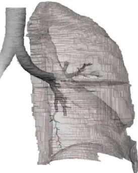
The lung model, trachea/bronchi model, and bronchi/bronchiole model (with rig) are shown in Fig-ure 8.
For approximately 600 slices, boundary lines were hand-drawn around the edges of the left lung, as well as around the trachea and dis-cernible bronchi (Figures 6 and 7). The computer then generated a 3D model from the stack of boundary lines, and the model was saved as an OBJ file and imported into Maya.
In order to ensure that the bron-chi/bronchiole model and the lung model were approximately the same scale, Russo’s (2007) tra-chea/bronchi model was used as a guide. The 3D Doctor model was scaled in Maya so that its trachea and bronchi portions fit directly over Russo’s model. The two mod-els were then scaled so that the
Figure 5 Left side view of the final bronchi/bronchiole model. A Maya rig was created in the model, with a joint at each point of bifurcation. Each joint’s angle of rotation in Maya’s z-axis is listed.
Joint Angle (°)
Figure 3 Anterior view of the final bronchi/bronchiole model, with the branch orders labelled. The sequence of orders remains the same as in Figure 1, however the directions of the branch-es was altered to fit the model within the lower posterior region of the left-lung model created with 3D Doctor.
Figure 4 Left side view of the final bronchi/bronchiole model, with the branch orders labelled. A rig was created with a joint at each point of bifurcation, and the joints were rotated in the z-axis in order to fit the model within the lower posterior region of the left-lung model created in 3D Doctor. 23a 22a 21a 20a 19b 18b 17b 16b 15b 14b 13b 12b 11b 10b 18a 17a 16a 15a 14a 13a 12a 11a 10a 19a 9b 7b 8b 23a 22a 21a 20a 19b 18b 17b 16b 15b 14b 13b 12b 11b 10b 18a 17a 16a 15a 14a 13a 12a 11a 10a 19a 9b 7b 8b
6 -4.887
7 -18.957
8 6.272
9 0
10 25.688
[image:9.612.69.545.75.507.2]IMAGING THE AIRWAYS
Figure 8 3/4 view in Maya of the left-lung model created in 3D Doctor, Russo’s trachea/ bronchi model, and the bronchi/bronchiole model (with joints, which are colored). The trachea and bronchi portions of the lung model were scaled to fit over Russo’s trachea/ bronchi model, and the bronchi/bronchiole model was angled to fit within the lung model. Figure 6 In 3D Doctor, boundaries (green lines) were drawn
around the edges of the lungs, as well as around the trachea and discernible bronchi, for approximately 600 Female Visible Human Project slices.
Figure 7 A screen shot from 3D Doctor with the list of slices (top left), the boundary outline from an anterior view (bottom right), and the boundary outline from a side view (bottom left). At this stage, boundaries for only the top portion of the lung were completed.
CONCLUSIONS
Creation of the bronchi/bronchiole (generations 6-19) model provided valuable experience in problem solving, as multiple challenges were overcome:
• where to obtain data since the lower generations are not discern-ible in the VHP slices, and no cast of those structures was available for SEM analysis
• how to arrange the branches and angle them anteriorly and posteri-orly, since the Horsfield et al. (1971) article does not provide such data.
The project was also a reinforce-ment of modeling skills using Maya and a learning experience using 3D Doctor.
After the bronchi/bronchiole model was completed in Maya, it was ex-ported as an OBJ file and success-fully imported into VP-Sculpt. Cur-rent RIT students in Mechanical Engineering and Medical Illustration will connect the model to the up-per respiratory and acinus models and conduct computational flow dynamics (CFD) studies with the complete airway model.
To the best of our knowledge, this model will be the first model of a
[image:10.612.74.348.293.636.2]IMAGING THE AIRWAYS
complete respiratory pathway–one that extends from where oxygen enters to where gas exchange oc-curs with the blood.
Future plans with the complete air-way model include studying the ef-fects of changes in lung morphom-etry due to certain disease states, such as asthma. In an asthmatic, the airways become contricted; in Maya, the dimensions of the airway model components can be altered (e.g., di-ameters reduced) to represent the airway of an asthmatic.
Knowledge of how airflow and par-ticle deposition compare between asthmatic and healthy airways would aid in the treatment of asthma, in-cluding the design of more effective inhalation therapy methods.
Future plans also include using more of Horsfield et al.’s data to constuct a pathway model for each lobe of the left and right lungs. CFD research with such models would show how and where air flows and particles deposit not only within each pathway, but also throughout the respiratory tree. Mechanical Engineering researchers would also be able to determine the transition point (i.e, the point at which parti-cles stop moving by convection and begin moving by diffusion) for each lobe.
Also, once more of the airways are constructed, a 3D printout of the entire model will be generated for demonstration purposes.
IMAGING THE AIRWAYS
gram used in common practice to study particle deposition.
BACKGROUND
Research for the IMAGING THE AIRWAYS thesis project was initi-ated in Summer 2007. An extensive literature review about the respi-ratory system was conducted, and several articles of current interest were selected as references. Spe-cifically, articles were chosen con-cerning nanoparticle translocation across the respiratory membrane.
According to Orberdorster et al. (2005), “Berryet al. (1977) were the first to describe the translocation of NSPs (nanosized particles) across the alveolar epithelium.” Berry et al. (1977) reported that 30 minutes after injecting 30-nm colloid gold particles into the tracheas of rats, the particles were found within platelets of the alveolar capillaries.
In more recent studies with rats and humans, UFPs (ultrafine par-ticles) have been shown to cross from the lungs into the systemic cir-culatory system to reach the liver, heart, spleen, lymph nodes, kidneys, and bone marrow (Orberdorster et al. 2005).
Nanoparticles, NSPs, NPs, and UFPs
According to McShane (2006), “No standard definitions have been es-tablished for the terms UFPs and nanoparticles, which has led to some confusion because the words are often used interchangeably.” From the articles researched, four terms were encountered: nanopar-ticles, NSPs (nanosized particles), NPs (engineered nanoparticles), and UFPs (ultrafine particles). All four terms refer to particles with diameters <100 nm. However, the origin of the particles differ.
Par t I.2 ORIGINAL THESIS STATEMENT, BACKGROUND
Part I.2 Respiratory Membrane Modeling of the respiratory membrane at the cellular and molecular levels in order to visualize nanoparticle trans-port from the lungs into the blood-stream.
ORIGINAL THESIS STATEMENT
Gas exchange in the lung requires the diffusion of molecules across an extremely thin membrane, known as the blood-air barrier. With a thick-ness of only 500 nm (nanometers) or less, this membrane represents the interface between a capillary lumen and a pulmonary alveolar air space.
Other 3D models of the respira-tory system do not extend beyond the alveolar level (~250,000 nm in diameter). The goal of this project is to continue this visual reduction to the nanoscale level (less than 100 nm), in an effort to model cel-lular and molecular detail of the respiratory membrane’s five main components: (1) surfactant (a lipid monolayer), (2) surface lining fluid, (3) alveolar epithelial cells, (4) base-ment membrane, and (5) endothe-lial cells.
Recent research has shown that nanoparticles (particles less than 100 nm in at least one dimension) can cross the respiratory mem-brane; however, the mechanisms of transport are not well known.
In order to understand the pos-sible health effects and medical ap-plications of nanoparticle inhalation, use of virtual and real models will help to define these mechanisms of transport.
In particular, respiratory membrane models created in Maya will serve as models in a computational flow dynamic engineering software
pro-NPs are manufactured, or engi-neered, particles, created through the growing field of nanotechnology. Knowles (2006) defines nanotech-nology as: “the design, character-ization, production, and application of structures, devices, and systems by controlling shape and size at the nanometer scale.” Further, Orber-dorster et al. (2005) state that the term NP “includes only spherical [particles]; other engineered nano-sized structures will be labeled ac-cording to their shape, for example, nanotubes, nanofibers, nanowires, nanorings, and so on.”
UFPs are created unintentionally as by-products of natural and anthro-pogenic processes. Gwinn and Val-lyathan (2006) state that the term ultrafine “is frequently used to de-scribe nanometer-size particles that have not been intentionally pro-duced but are the incidental prod-ucts of processes involving industri-al, combustion, welding, automobile, diesel, soil, and volcanic activities.”
Nanoparticles and NSPs are general terms that include NPs and UFPs. Knowles (2006) defines nanopar-ticles as parnanopar-ticles that are “found widely in the natural world as prod-ucts of photochemical and volcanic activity, created in plants and algae, and from products of combustion, food cooking, and diesel exhaust; also manufactured particles such as metal oxides (titanium dioxide, zinc oxide); used in cosmetics, textiles, paints, targeted drug delivery sys-tems, and sunscreens.”
Health Effects of Nanopar-ticles
IMAGING THE AIRWAYS
Par t I.2 BACKGROUNDincreased biologic activity can be either positive and desirable (e.g., antioxidant activity, carrier capacity for therapeutics, penetration of cel-lular barriers for drug delivery) or negative and undesirable (e.g., toxic-ity, induction of oxidative stress or of cellular dysfunction), or a mix of both.”
Harmful effects of UFPs to the respiratory system and extrapul-monary organs have already been documented through studies with humans, rats, and in vitro cell cul-tures. Adverse respiratory and cardiovascular effects resulting in morbidity and mortality have been associated with UFPs in air pollution (Orberdorster et al. 2005; Gwinn and Vallyathan 2006). In laboratory experiments, UFPs have induced in-flammatory responses in rats and in vitro cell cultures, and caused oxida-tive stress to in vitro cell cultures, resulting in changes to gene expres-sion and cell signalling pathways (Orberdorster et al. 2005).
While such effects may be undesir-able for normal cells, they could be utilized through NPs for anticancer treatments and gene therapy appli-cations. Also, because NPs can be coated with biological micromol-ecules such as antibodies and pro-teins and can travel to target organs from the respiratory system, they are being developed for drug deliv-ery and as in vivo and in vitro immu-nofluorescent probes (Gwinn and Vallyathan 2006).
The potential for NPs to cause adverse health effects still exists, however, particularly for NPs that may be released into the environ-ment through maufacturing pollu-tion and degradapollu-tion of products through normal use and disposal. According to McShane (2006), “... the current state of knowledge concerning the exposure risks as-sociated with nanotechnology are
poor.” Gwinn and Vallyathan (2006) state: “One major challenge facing industry and government is the lack of information on the possible ad-verse health effects caused by ex-posure to different nanomaterials.” Therefore, as Yacobi et al. (2007) summarize, “Further knowledge about the mechanisms by which particles injure, interact with and/or are transported across the alveo-lar epithelium is thus of consider-able importance for understanding health effects related to inhalation of ultrafine [and engineered nano-] particles in ambient air.”
Mechanisms of Transport
While numerous studies have shown that nanoparticles cross the respiratory membrane to enter the bloodstream and extrapulmonary organs, many studies also state that little is known about how nanopar-ticles cross the respiratory mem-brane:
• Berry et al. (1977): “The pathways by which inhaled metallic particles cross the gas exchanging surface in the pulmonary alveoli (where only the finest particles are deposited), must be identified in order to study the action of those contaminants on the respiratory system and on the body generally. The mechanism of this migration still remains uncer-tain and controversial.”
• Churg (2000): “The determinants of particle uptake remain poorly defined....It is still impossible to provide any generalized explana-tion of the marked differences in uptake seen with different types of particles, and little is known of the mechanisms of this process.”
• Hoet et al. (2004): “The litera-ture on the translocation of very small particles from the lung into the blood circulation is limited and often conflicting.”
• Geiser et al. (2005): “To date, the mechanisms by which UFPs pen-etrate boundary membranes...are largely unknown.”
• Gwinn and Vallyathan (2006): “...currently the process of UFP translocation is poorly under-stood...”
• Rothen-Rutishauer et al. (2006): “So far, little is known about the in-teraction of nanoparticles with lung cells, the entering of nanoparticles, and their transport through the blood stream [sic] to other organs. ...The entering mechanisms for nanoparticles into cells are still not yet known.”
Such statements indicate a sig-nificant need for research about nanoparticle mechanisms of trans-port across the respiratory mem-brane. Therefore, it was decided for the IMAGING THE AIRWAYS thesis project to create a model of the re-spiratory membrane using available data and to study fluid flow and par-ticle movement through the model using CFD (compuational flow dy-namics) analysis.
Maya models were created of the respiratory membrane’s five main layers: surfactant (a lipid monolay-er), surface lining fluid, an alveolar Type I epithelial cell (with lipid bi-layer and caveolae), basement mem-brane (made of proteins perlecan, laminin, entactin, and collagen IV), and an endothelial cell (with lipid bilayer and caveolae).
However, challenges existed to us-ing the model in Mechanical Engi-neering CFD studies:
(1) Mechanisms of transport through or between cells
IMAGING THE AIRWAYS
• diffusion
• caveolae transport (transcytosis) • receptor-mediated transcytosis • movement between cellular tight junctions
Diffusion and movement through cellular tight junctions could easily be studied through CFD analysis. However, the current model rep-resents only a representative sec-tion of an alveolar Type I cell and an endothelial cell; therefore, another model would have to be construct-ed in order to include cellular tight junctions. Further, CFD cannot eas-ily be used to study transcytosis be-cause the process involves biologi-cal and chemibiologi-cal factors, including caveolae movement along cytoskel-etal elements.
(2) Properties of basement membrane proteins
Although the basement membrane proteins were modeled based on available data, the representations are more iconic than literal. Even space-filling, ball-and-stick, and sur-face models are representations of the spaces occupied by electrons, and do not represent molecules as literal solid structures. Therefore, in order to run CFD analysis through the basement membrane model, we would need to learn more about the chemical properties of the indi-vidual proteins (such as polarity and other factors that could influence interactions with nanoparticles).
(3) Properties of nanoparticles Different nanoparticle properties, such as size, charge, surface chem-istry, and concentration of particles may influence which mechanism of transport is used. Therefore, for our study, we would need to learn more about the properties of cer-tain types of nanoparticles.
Moving Forward
In order for our research to be credible, we would need to work
with experts in biology, chemistry, and nanotechnology–people who could not only generate new data for us to work from, but to also help us interpret existing data.
With these concerns in mind, a meeting was established in the Fall 2007 quarter with Dr. Gunter Orberdorster, Professor of Environ-mental Medicine at the University of Rochester and author of numerous papers about nanotoxicology. Dr. Orberdorster was shown the respi-ratory membrane model; however, he confirmed that much informa-tion is lacking in the scientific com-munity in terms of understanding how nanoparticles cross the respi-ratory membrane.
The decision was eventually made to change the focus of the thesis research from nanoparticle translo-cation across the respiratory mem-brane to completing the respiratory pathway model using data that was known to exist. Other Mechanical Engineering students could then follow Russo’s (2007) methods for conducting the computational flow dynamics studies, and Russo’s data could be compared with the newly generated data.
Research using the respiratory membrane model would be con-ducted when more resources and background data became avail-able. In the meantime, the model was used for promotional materials about the IMAGING THE AIRWAYS project and in the Human Visualiza-tion Project animaVisualiza-tion about the structure of the respiratory sys-tem.
THE BODY OF WORK
Over Summer 2007, Maya models were constructed of the respiratory membrane’s five main components: surfactant (a lipid monolayer),
sur-face lining fluid, an alveolar Type I epithelial cell (with lipid bilayer and caveolae), basement membrane (made of proteins perlecan, laminin, entactin, and collagen IV), and an en-dothelial cell (with lipid bilayer and caveolae).
The models were constructed from available data and are to scale.
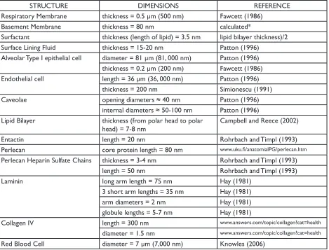
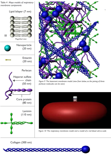
Table 3 lists the dimensions of each respiratory membrane component and the references from which the data was obtained. Table 4 shows some of the models and their rela-tive sizes, and Figure 9 shows the basement membrane model. Fig-ure 10 shows the complete respi-ratory membrane model in scale compared to a model of one red blood cell, and Figure 11 labels the components of the complete respi-ratory membrane model.
Orientation of the basement membrane components
The basement membrane models were organized according to de-scriptions by Crouch et al. (1991) and from an illustration of a base-ment membrane by David Goodsell (2000).
The entactin models were placed to link the collagen IV models to the laminin models where the short arms of laminin intersect.
The core protein of the perlecan models were placed within the base-ment membrane meshwork, with the heparan sulfate chains extending along the surface of the basement membrane adjacent to the epithe-lial cells. According to Crouch et al. (1991), the heparan sulfate chains form a negatively charged barrier that prevents the passage of nega-tively charged molecules greater than 3-5 nm in diameter.
The perlecan models were arranged in groups of three, according to the
IMAGING THE AIRWAYS
Par t I.2 THE BODY OF WORKSTRUCTURE DIMENSIONS REFERENCE
Respiratory Membrane thickness = 0.5 µm (500 nm) Fawcett (1986)
Basement Membrane thickness = 80 nm calculated*
Surfactant thickness (length of lipid) = 3.5 nm lipid bilayer thickness)/2 Surface Lining Fluid thickness = 15-20 nm Patton (1996)
Alveolar Type I epithelial cell diameter = 81 µm (81, 000 nm) Patton (1996) thickness = 0.2 µm (200 nm) Fawcett (1986) Endothelial cell length = 36 µm (36, 000 nm) Patton (1996)
thickness = 200 nm Simionescu (1991)
Caveolae opening diameters ≈ 40 nm Patton (1996)
internal diameters ≈ 50-100 nm Patton (1996) Lipid Bilayer thickness (from polar head to polar
head) = 7-8 nm
Campbell and Reece (2002)
Entactin length = 20 nm Rohrbach and Timpl (1993)
Perlecan core protein length = 80 nm www.uku.fi/anatomialPG/perlecan.htm
Perlecan Heparin Sulfate Chains thickness = 3-4 nm Rohrbach and Timpl (1993) length = 50 nm Rohrbach and Timpl (1993)
Laminin long arm length = 75 nm Hay (1981)
3 short arm lengths = 35 nm Hay (1981) arm diameters = 2 nm Hay (1981) globule lengths = 5-7 nm Hay (1981)
Collagen IV length = 300 nm www.answers.com/topic/collagen?cat=health
diameter = 1.5 nm www.answers.com/topic/collagen?cat=health
[image:15.612.75.544.380.737.2]Red Blood Cell diameter = 7 µm (7,000 nm) Knowles (2006)
Table 3 Dimensions used to create the respiratory membrane model
*The thickness of the basement membrane was calculated using the following formula:
([thickness of respiratory membrane] - [(thickness of surfactant) + (thickness of surface lining fluid) + (thickness of alveolar Type I epithe-lial cell) + (thickness of endotheepithe-lial cell)]).
Goodsell (2000) illustration.
The laminin models were connect-ed by the globules at the ends of the four arms. The models were rigged with a Maya joint system in order to bend them around the other base-ment membrane protein models.
Future Work
In the current model, the heparan sulfate chains extend only toward the alveolar Type I epithelial cell. Future work with the model should involve creating a second layer of perlecan models oriented in the op-posite direction, with the heparan sulfate chains facing the endothelial cell.
The collagen IV models were
origi-nally arranged with bonds between the globules of two molecules and between the N-terminals of four molecules. However, the models were rearranged in order to bet-ter simulate the greabet-ter density of collagen IV molecules beneath the meshwork of entactin, laminin, and perlecan, as illustrated by David Goodsell (2000).
As shown in Figure 9, the collagen IV models are still arranged with bonds between two globules; how-ever, the ends of the models are no longer arranged in groups of four. Future work with the model should involve using the collagen IV models in their orginal orientation.
The orginal, rigid arrangement of
collagen IV was based on a diagram by Crouch et al. (1991); however, the authors state that their model represents “the most extended structure, which is likely to be very much condensed via lateral aggrega-tion.” Therefore, the original col-lagen IV models could be modified, such as with a Maya joint system, in order to create a more condensed collagen IV meshwork.
IMAGING THE AIRWAYS
Magnified view
Table 4 Maya models of respiratory-membrane components
[image:16.612.227.513.65.394.2]Collagen (300 nm)
Laminin
(110 nm)
Perlecan
Entactin
(20 nm)
Nanoparticle
(20 nm)
Lipid bilayer (7 nm)
[image:16.612.70.539.66.725.2]Figure 10 The respiratory membrane model and a model of a red blood cell, to scale Figure 9 The basement membrane model (view from below, as the joining of three perlecan molecules can be seen)
Heparan sulfate
chain
(50 nm)
Core protein
(80 nm)
IMAGING THE AIRWAYS
Figure 11 Complete model of the respiratory membrane
Surfactant Surface lining fluid Lipid bilayer
Alveolar Type I epithelial cell
Caveolae
Basement membrane Lipid bilayer
Lipid bilayer
Lipid bilayer Endothelial cell
Caveolae
Blood plasma Nanoparticle
IMAGING THE AIRWAYS
PART I.2 CONCLUSIONSCONCLUSIONS
Creating the respiratory membrane model honed valuable research skills, as well as modeling skills in Maya.
The respiratory membrane model and its use in the Human Visualiza-tion Project animaVisualiza-tion were signifi-cant first steps into this area of re-search, not only for RIT researchers, but also for the scientific community at large. As previously stated, little is known about the mechanisms by which nanoparticles cross the respiratory membrane. However, piecing together what data is cur-rently available has allowed for the creation of a model that will serve as the foundation for RIT’s future studies about the respiratory mem-brane. In fact, such research is being conducted over the Summer 2008 quarter, where the model was suc-cessfully imported into VP-Sculpt.
Again, to the best of our knowledge, this model is the first model of the respiratory membrane–one that in-cludes all layers and their compo-nents (i.e., surfactant; surface lining fluid; an alveolar epithelial cell with lipid bilayer and caveolae; the base-ment membrane with proteins per-lecan, laminin, entactin, and collagen IV; and an endothelial cell with lipid bilayer and caveolae).
IMAGING THE AIRWAYS
PART I.3 Promotional Materials Creation of promotional materials for the project to educate the RIT commu-nity and other interested audiences.
ORIGINAL THESIS STATEMENT
No written proposal was submitted for Part 1.3 of the project. Howev-er, it was discussed with thesis advi-sors that the promotional materials, featured in the March 17-April 9, 2008 thesis show, would be a poster, a website, and a video.
BACKGROUND
The poster, postcard, website, and video were inspired and created through assignments in two classes: 1. An independent study in Nancy Ciolek’s Information Design class 2. Ann Pearlman’s Digital Video class
The Information Design class greatly helped to reinforce the principles of good design, such as structure (e.g., alignment through use of the grid system), emphasis (e.g., of words and images with use of color, size, and style), and information flow. Principles were reinforced with ex-amples from innovators in informa-tion design, such as Edward Tufte, as well as through class critiques, both throughout the design process and on project due dates.
The Digital Video class was an in-valuable introduction to Final Cut Pro and helped to reinforce the principles of filming and documen-tary design, such as digital-video-camera use, lighting, sound, story-boarding, titling, and editing. Virginia Orzel, an RIT alum and currently an independent filmmaker, also assisted (outside of class) with aspects such as image enhancement (e.g., size and color correction).
THE BODY OF WORK
Promotional materials for the IM-AGING THE AIRWAYS thesis proj-ect consist of a poster, a postcard, a website, and a one-minute video. These materials were presented in the March 17-April 9, 2008 the-sis show in the Bevier Art Gallery. The poster, website, and video were also presented at Imagine RIT, May 3, 2008.
Images associated with the upper respiratory and acinus models were acquired from a PowerPoint de-signed by Jackie Russo for her thesis defense. All other research images were created from Parts 1.1 and I.2 of the IMAGING THE AIRWAYS thesis project.
THE POSTER
Figure 12
Dimensions: 35” x 43” Media: Illustrator, Photoshop
The IMAGING THE AIRWAYS poster was designed in Professor Nancy Ciolek’s Information Design class. Many design principles were applied, such as:
• alignment of text and images through use of the grid system • establishment of information hier-archy through use of font size and color
• establishment of relationships among pieces of information through use of color (e.g., all mod-els created as part of the IMAGING THE AIRWAYS thesis project are highlighted in orange-red to match the title along the left side of the poster)
• information flow (e.g., the com-plete pathway model is the largest and most prominent image, drawing attention first to the center/upper left of the poster; the eye is then drawn around the poster in a clock-wise direction.)
Image color, size, and resolution were also considered and adjusted for printing in CMYK at a relatively large size.
THE POSTCARD
Figures 13-14
Dimensions: 4.25” x 6” Media: Illustrator, Photoshop
The postcard was designed specifi-cally to advertise the March 17-April 9, 2008, thesis show and for visitors to take. The design of the front of the postcard mimics the design of the poster.
THE WEBSITE
Figures 15-29
Media: Flash, Illustrator, Photoshop http://www.betsyskrip.com/thesis
The IMAGING THE AIRWAYS web-site was first designed as a Power-Point in Professor Nancy Ciolek’s Information Design class. The im-ages, text, and design elements were then transferred into Flash.
The design for the original Power-Point also influenced the design for all of the IMAGING THE AIRWAYS promotional materials. The colors, fonts, project logo, and other ele-ments are consistent among the website, poster, postcard, and video.
The website buttons were designed using Photoshop and Illustrator. Some button logos were created in Photoshop by altering the origi-nal images (i.e., isolating the models from their backgrounds and making the models solid white). All other logos were created in Illustrator either with the pen tool or with Wingding and Apple Symbols char-acters.
IMAGING THE AIRWAYS
Par t I.3 THE BODY OF WORK: POSTERIMAGING THE AIRWAYS
Par t I.3 THE BODY OF WORK: POSTCARDFigure 13 IMAGING THE AIRWAYS Postcard (front)
IMAGING THE AIRWAYS
Figure 14 IMAGING THE AIRWAYS Postcard (back) 4.25” x 6” Illustrator
IMAGING THE AIRWAYS
Par t I.3 THE BODY OF WORK: WEBSITEIMAGING THE AIRWAYS
Figure 16 IMAGING THE AIRWAYS Website: Anatomy 780 x 600 px Flash, Illustrator, Photoshop
IMAGING THE AIRWAYS
Figure 17 IMAGING THE AIRWAYS Website: Model 780 x 600 px Flash, Illustrator, Photoshop
IMAGING THE AIRWAYS
Figure 18 IMAGING THE AIRWAYS Website: Oral Cavity Model 780 x 600 px Flash, Illustrator, Photoshop
IMAGING THE AIRWAYS
Figure 19 IMAGING THE AIRWAYS Website: Larynx Model 780 x 600 px Flash, Illustrator, Photoshop
IMAGING THE AIRWAYS
Figure 20 IMAGING THE AIRWAYS Website: Trachea Model 780 x 600 px Flash, Illustrator, Photoshop
IMAGING THE AIRWAYS
Par t I.3 THE BODY OF WORK: WEBSITEIMAGING THE AIRWAYS
Par t I.3 THE BODY OF WORK: WEBSITEIMAGING THE AIRWAYS
Par t I.3 THE BODY OF WORK: WEBSITEIMAGING THE AIRWAYS
Par t I.3 THE BODY OF WORK: WEBSITEIMAGING THE AIRWAYS
Par t I.3 THE BODY OF WORK: WEBSITEIMAGING THE AIRWAYS
Par t I.3 THE BODY OF WORK: WEBSITEIMAGING THE AIRWAYS
Par t I.3 THE BODY OF WORK: WEBSITEIMAGING THE AIRWAYS
Par t I.3 THE BODY OF WORK: WEBSITEIMAGING THE AIRWAYS
Par t I.3 THE BODY OF WORK: WEBSITEIMAGING THE AIRWAYS
Par t I.3 THE BODY OF WORK: VIDEOTHE VIDEO
Title: IMAGING THE AIRWAYS Promotional Video
Duration: 1 min Medium: FInal Cut Pro
h t t p : / / w w w. b e t s y s k ri p. com/thesis
(Movie section)
The IMAGING THE AIRWAYS Pro-motional Video is a “sneak peek” at the overall thesis work, meant to at-tract people’s attention and interest. The video does not fully explain the research or the images presented.
However, the video is contained within the website where such in-formation can be obtained and does summarize the project, condensing all of the most important informa-tion into a one-minute, visually and aurally aesthetic presentation. Spe-cifically, images of the models and segments from interviews with Dr. Doolittle and Dr. Robinson were carefully selected to highlight the most important aspects of the the-sis research.
The video presents: • the project’s participants
Interviews introduce Dr. Doolittle and Dr. Robinson (Figure 31), and Dr. Doolittle mentions those in-volved.
• the project’s purpose
Dr. Doolittle explains that the proj-ect involves looking at particle de-position in the human lung; Dr. Rob-inson explains that the model will be a pathway from the upper airway to the site of gas exchange.
• the models
Models of the airway, respiratory membrane (Figure 32), and alveolar sacs with capillaries (Figure 33) are featured.
• how the models were created
Images from 3D Doctor are shown (Figure 30); they are explained else-where on the website.
• significant aspects of the project
Dr. Doolittle highlights the model of the basement membrane; Dr. Rob-inson states that the project is the first to create a complete model of the airways from the atmosphere to the site of gas exchange.
Methods
The video was created in Professor Ann Pearlman’s Digital Video class using Final Cut Pro. Many meth-ods had been learned in previous class assignments (e.g., principles of digital-video-camera use, light-ing, sound, storyboardlight-ing, titllight-ing, and editing). Some methods, however, were learned specifically through
creation of this video:
• Overlapping animations
Still images were animated in Final Cut by keyframing image proper-ties such as location, scale, and opacity. The animations were then overlapped with each other or with still images. Examples include the nanoparticle moving across the re-spiratory membrane (Figure 32, left) and the project logo moving with the acinus model (Figure 33, right).
•Importing QuickTime movies The movie of the alveolar sacs (Fig-ure 33) is a QuickTime file import-ed into Final Cut Pro. Discovery of this method for bringing Maya- and Flash-generated animations into Fi-nal Cut made creation of the HVP and CollaboRITorium animation possible.
• Importing a QuickTime movie into Flash
Once the video was completed in Fi-nal Cut, it was exported as a Quick-Time file and imported into the Flash website. Importing involves converting the QuickTime file to an FLV (Flash Video) file. Learning this method fascilitated importing the HVP and CollaboRITorium anima-tion into the HVP website.
IMAGING THE AIRWAYS
Par t I.3 THE BODY OF WORK: VIDEOFigure 31 Interviews with Dr. Richard Doolittle and Dr. Risa Robinson
Figure 32 Left, nanoparticle crossing respiratory membrane; right, basement membrane proteins
IMAGING THE AIRWAYS
Par t I.3 CONCLUSIONSCONCLUSIONS
The Poster and Postcard
Creation of the poster and postcard as part of Professor Nancy Ciolek’s Information Design class was an in-valuable learning experience in the principles of design. Projects fol-lowing the thesis project have been greatly influenced by the experience and knowledge gained through the Information Design class.
The Website
Design principles were reinforced through creation of the website as well, which was first designed as a PowerPoint presentation in Pro-fessor Ciolak’s Information Design class. The PowerPoint was created before the poster; therefore, de-signing the PowerPoint was also a worthwhile experience in gathering and summarizing information for presentation to a specific audience and inspired the style for all of the project’s promotional materials.
Creating the website reinforced skills in Flash, as well as in Photo-shop and Illustrator (particularly with designing the buttons). The procedure for importing a Quick-Time movie into Flash as an FLV (Flash Video) file was also learned.
The Video
IMAGING THE AIRWAYS
dents explore a topic of current research on campus through inter-actions with faculty and research groups while learning about aspects of science communication and pre-sentation and developing a digital in-teractive, immersive, science learn-ing experience.”
This project will help to greatly en-hance my skills with Maya, particu-larly in texturing and creating realis-tic environments. Such a large-scale teaching project will also test and greatly increase my medical illustra-tion skills—particularly the art of organizing and presenting informa-tion in understand, easy-to-navigate, and attractive formats.
BACKGROUND
The Human Vizualization Proj-ect (HVP)
The HVP is a collaboration to cre-ate an interactive model of the hu-man body and an online learning platform available for students and teachers both within and outside the RIT community. The project will consist of models and anima-tions of the body’s systems (e.g., skeletal, muscular, cardiovascular, respiratory, urinary, endocrine, and digestive), both at the macroscopic and microscopic levels.
The team spans different graduat-ing classes and disciplines: Biological Sciences and Chemistry (College of Science), Medical Illustration (Col-lege of Imaging Arts and Sciences), Computer Gaming and Information Technology (College of Computing and Imaging Sciences), and Mechani-cal Engineering (College of Engi-neering).
The CollaboRITorium
The CollaboRITorium is an immer-sive learning environment and an in-cubator for the design of new tech-nologies, designed by RIT students
Par t II ORIGINAL THESIS STATEMENT, BACKGROUND
II. Creation of an Educational Animation about the Respiratory System for Use in the Human Vi-sualization Project and CollaboRI-Torium
ORIGINAL THESIS STATEMENT
In previous quarters, Maya (a 3D computer graphics program) was used to create models of the re-spiratory tract and the rere-spiratory membrane’s five main components: (1) surfactant (a lipid monolayer), (2) surface lining fluid, (3) alveolar epithelial cells, (4) basement mem-brane, and (5) endothelial cells.
In the Spring 2008 quarter, an ani-mation will be made using the pre-viously created models in order to educate viewers about the respira-tory system and about current stud-ies in nanoparticle transport across the respiratory membrane into the bloodstream.
The work will be projected in RIT’s CollaboRITorium, a specialized classroom designed by RIT students. The CollaboRITorium features four large (wall-height) screens whose orientation can be changed to form a cube, making the learning experi-ence immersive. The work will also be available online as part of RIT’s Human Visualization Project, an in-teractive learning tool created by RIT students.
The project will be created through two independent studies: the ani-mation and website will be created through collaboration with profes-sor Shaun Foster from the Com-puter Graphics Design Department; projection in the CollaboRITorium will be accomplished through an in-dependent study in Dr. Jake Noel-Storr’s Honors class Frontiers of Science II, a course in which
“stu-and faculty.
Spearheaded by Dr. Jon Schull in In-formation Technology and his class Innovation and Invention, the project currently features three immersive DOMEs (Digital Omnidirectional Multimedia Environments). Each DOME consists of four screens that can be folded into a cube. Viewers stand inside of the cube as images are projected onto each of the four walls, thus creating an immersive environment.
Furthermore, most images and ani-mations projected in the cubes are interactive. Using a Wii remote, viewers can navigate through a vir-tual landscape or an educational game and rotate, zoom, and pan through 3D models.
Independent Studies
The IMAGING THE AIRWAYS ani-mation and revised Human Visualiza-tion Project website were created in the Spring 2008 quarter through two independent studies:
1. A three-credit independent study with Shaun Foster from the Com-puter Graphics Design Department 2. A one-credit independent study in Dr. Jake Noel-Storr’s Honors class, Frontiers of Science II.
For the animation, several new methods using Maya were learned and implemented through working with Shaun Foster:
• use of the Paint Effects tool and manipulation of the resulting mod-els to create the bronchial tree (Fig-ure 38)
• the creation and animation of glowing edges (e.g., the texture on the human figure) using a ramp shader
• the creation of metallic-looking surfaces for the basement mem-brane proteins using an environ-mental ball shader (Figures 51 and 53)
IMAGING THE AIRWAYS
Par t II BACKGROUND, THE BODY OF WORK: ANIMATIONH.264 codec
Professor Foster also provided valu-able feedback about the aesthetics, pace, and understandability of the animation at its various stages of development.
The Frontiers of Science II class re-quired students to research a topic of their choice and develop content to present their research in the Col-laboRITorium classroom (A-400).
Work completed as part of the in-dependent study included:
• creating an interactive platform (i.e., the revised Human Visualiza-tion Project website) to feature the animation
• designing part of the animation to extend to all four walls of the cube.
THE BODY OF WORK
Animation and website at:
h t t p : / / w w w. b e t s y s k ri p. com/hvp
(Note: The animation is located in the Respiratory section.)
THE ANIMATION
Duration: 5 min
Media: Flash, Final Cut Pro
The HVP and CollaboRITorium animation is a video to educate viewers about the structure and function of the respiratory system and about current research (i.e., nanoparticles and the respiratory membrane model). Unlike in the thesis promotional video, the im-ages in the animation are explained through narration.
The animation illustrates gas ex-change at the macroscopic level (Figures 36 and 37) and microscopic level (Figure 44) and guides view-ers through this visual reduction in size.
The video contains six main sec-tions:
1. Introduction
2. O2 and CO2 Exchange
3. The Respiratory Membrane 4. Current Research
5. The Basement Membrane 6. Summary
Methods
The overall animation consists of many smaller animations created in Maya and Flash. These short anima-tions were exported from Flash as QuickTime files and imported into Final Cut Pro, where they were ar-ranged and compiled with narration and music.
Introduction
The animation first provides an orientation of the lungs inside the human body (Figures 34 and 35). The lung models were created in Maya in Summer 2007 using Netter illustrations (Netter, 1979) as ref-erences. The model of the human body was purchased by the Human Visualization Project and has been used in other student animations for the HVP. The larynx model was created by Weisman (2007), and the trachea/bronchi model was created by Russo (2007).
To visually explain the inhalation of oxygen and exhalation of carbon dioxide, the thoracic wall and lungs were animated in Maya to expand and contract (Figures 34 and 35), and colored layers were animated in Flash to highlight the path between the atmosphere, lungs, and body (Figures 36 and 37).