Int. J. Electrochem. Sci., 13 (2018) 4267 – 4275, doi: 10.20964/2018.05.42
International Journal of
ELECTROCHEMICAL
SCIENCE
www.electrochemsci.org
Short Communication
Effects of Graphene Oxide on the Conductivity and Capacitance
of Polypyrrole
Changjing Fu2, Qiang Ma1,*, Hongfan Liu1, Wenyan Tang1 1
School of Electrical Engineering & Automation, Harbin Institute of Technology, Harbin 150001, P.R.China
2
School of Materials Science & Engineering, Heilongjiang University of Science &Technology, Harbin 150022,P.R. China
*
E-mail: [email protected]
Received: 5 January 2018 / Accepted: 28 February 2018 / Published: 10 April 2018
A polypyrrole and graphene oxide (PPy/GO) composite was synthesized by a chemical in situ polymerization method at low temperature to modify and improve the dispersibility and conductivity of polypyrrole. Graphene oxide was prepared by the modified Hummers’ method. The phase composition, microstructure, conductivity and capacitance of the composite were characterized and measured using XRD, SEM, a source meter and an electrochemical workstation, respectively. The results showed that pyrrole could evenly cover the surface of GO due to the oxygen-containing functional groups on the surface and edges of GO. The highest conductivity the composite achieved was 27 times higher than that of PPy. The specific capacitance of the composite remained at 389 Fg-1 under a current density of 2 Ag-1 after 1000 cycles, and the capacitance loss was only 3.47%, which exhibited that the PPy/GO composite had a high specific capacitance and good cycle stability as an electrode material for supercapacitors.
Keywords: Polypyrrole, Graphene oxide, In situ polymerization, Capacitance
1. INTRODUCTION
design the electrode material. Among the numerous electrode materials for supercapacitors, carbon materials were applied first and are still widely used as electrode materials [7-11].
In recent years, with the rapid development of conductive polymer materials, their excellent electrochemical properties have gradually improved [12-14]. Among them, polypyrrole is considered to be one of the best ideal electrode materials for supercapacitors, as it has good biocompatibility and stability [15]. Polypyrrole can be simply synthesized from readily available materials. Moreover, it has a reversible redox reaction with a high charge storage density [16, 17]. However, as a supercapacitor electrode material, polypyrrole shows poor mechanical performance, and its structure, which is composed of long polymer chains, is easily damaged in the process of charge/discharge cycling, resulting in attenuation of its specific capacitance [18]. To overcome the above problems of polypyrrole for use in supercapacitors, the construction of carbon materials and polypyrrole composites may be a promising strategy to obtain high-performance electrodes.
Graphene oxide, as a kind of carbon material, has not only a high specific surface area and good mechanical strength but also a large number of hydrophilic oxygen-containing functional groups [19, 20]. Therefore, graphene oxide is an effective substrate or template for the dispersion and polymerization of pyrrole [21]. With the rapid development of graphene, PPy/graphene and PPy/rGO composites have evoked tremendous attention as supercapacitor electrodes.. Although graphene has high electronic conductivity and large specific surface area which helps to make up the shortcoming of PPy, the instability of microstructure and the difficulty to dispersing are the common problems hard to solve for both of them, which is also one of the reasons resulting in the poor cycle performance of PPy/graphene and PPy/rGO electrodes. Thus, in view of the deficiency of PPy/grphene and PPy/rGO composites, in this article, a polypyrrole and graphene oxide (PPy/GO) composite was prepared by a chemical in situ polymerization method, which is scarcely reported as far as we known, and the effects of graphene oxide on the conductivity and cycle stability of polypyrrole were examined in detail.
2. EXPERIMENTAL
2.1. Raw materials & reagents
Pyrrole (py, molecular weight = 67.09), sodium lignosulphonate (96%) and ferric chloride hexahydrate (FeCl36H2O, AR, 99%) used for the polymerization of pyrrole were purchased from Sinopharm Chemical Reagent Co., Ltd. (Shanghai, China) and used without purification. The reagents used for the preparation of graphene oxide, such as potassium permanganate (95%), concentrated sulfuric acid (98%), concentrated hydrochloric acid (37%), sodium nitrate (99%) and hydrogen peroxide (30%), were all analytically pure, and distilled water was used to synthesize the materials.
2.2 Preparation of the PPy/GO composite
lignosulphonate as the doping agent, 0.002 mol sodium lignosulphonate and 100 mL distilled water were first added to a three-necked flask, which was then placed into an ice water bath accompanied by magnetic stirring for 15 min. After that, a certain amount of GO solution was added into the three-necked flask, and stirring was continued for another 15 min. Then, 2 mL of freshly distilled pyrrole was slowly injected into the mixed solution. It took approximately 1 h to achieve a homogeneous mixture under continuous stirring in an ice water bath. Meanwhile, ferric chloride hexahydrate was mixed with 100 mL distilled water and cooled in the ice water bath. The molar ratio of ferric chloride hexahydrate to pyrrole was 1.2. After 30 min, the ferric chloride mixture was transferred into a constant-pressure funnel, and the solution was slowly added dropwise into the three-necked flask. After a certain reaction time, all the products were treated by vacuum filtration and washed with distilled water and anhydrous ethanol until the filtrate was colorless. The final products were obtained after vacuum drying at 80°C for about 1 day.
2.3 Characterization of the PPy/GO composite
X-ray diffraction (XRD) analysis of the composites was carried out with a Rigaku-D/max diffractometer equipped with Cu Kα radiation (=0.15406 nm). The scanning range was set from 2θ = 10° to 90°, and the scanning rate was 5°min-1. The working current was controlled at 30 mA, and the accelerating voltage was 40 kV. The morphology of the prepared composites was observed by a Hitachi SU800 scanning electron microscope (SEM). The accelerating voltage was set to 15 kV, and the resolution was 9.4 nm.
2.4 Electrochemical measurements of the PPy/GO composite
The conductivity of the PPy/GO composite was measured by the DC four-probe method using a Keithley 2400 digital source meter. The composite powder was cold-pressed by a 769YP-24B powder compressing machine and attached with silver leads before testing.
The electrochemical properties were tested in a three-electrode system using an electrochemical workstation (CHI660E). A Pt wire and Ag/AgCl electrode were used as the counter electrode and reference electrode, respectively. The working electrode was obtained by ultrasonically dispersing 4 mg of the powder sample in 1 mL chitosan solution for 4 h and then dropping 6 L of the mixture onto a carbon electrode, which was then air dried. The galvanostatic charge/discharge test was performed over a range of -0.4 to 0.6 Ag-1 in saturated KCl solution.
3. RESULTS AND DISCUSSION
3.1. Conductivity of the PPy/GO composite
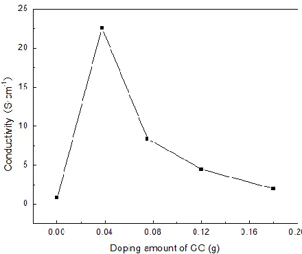
can be seen from Fig. 1 that with an increase in the GO content, the conductivity of the PPy/GO composite initially increased and then, after reaching the highest value, gradually decreased, which may be due to the fact that with an increase in GO content, the adsorption position and space of pyrrole expanded, inhibiting aggregation of the pyrrole monomer. In addition, a strong electrical interaction between the pyrrole monomer and GO exists. Moreover, as the result of the good stickiness of the block copolymer along with the help of magnetic stirring, a good conductive network formed, inducing an increase in the initial conductivity of the composite.
Figure 1. Effects of the introduction of GO on the conductivity of the /PPy/GO composite.
The highest conductivity of the composite (22.571 Scm-1) was achieved in the sample with the addition of GO controlled at 0.0375 g, which was more than 28 times higher than that of PPy (0.79 Scm-1). Moreover, this value is nearly 5 times that of the graphite nanosheet (NanoGs)/PPy composite (4.61 Scm-1) [23] and 7 times higher than that of the graphene/PPy (3.21 Scm-1) [24]. However, the conductivity of the composite decreased with an increase in the GO content after reaching the highest value of 22.571 Scm-1 This phenomenon was due to the fact that too much GO made the pyrrole too disperse to interact with other molecules and form a good conductive network, thus destroying the conductive path of PPy and GO, reducing the carrier mobility between PPy chains, and increasing the differences between energy bands, resulting in a decrease in the conductivity of the PPy/GO composite. When the addition of GO increased to 0.18 g, the conductivity of GO reduced to 2.0 Scm-1, closed to that of PPy. Besides, the high conductivity of PPy/GO composite also reveals that good 3D structure of the composite is even more important for achieving a high conductivity, though graphene and graphite has a higher conductivity than GO.
3.2. X-ray diffraction analysis of the PPy/GO composite
[image:4.596.187.407.209.394.2]
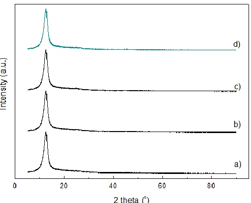
respectively. It can be clearly observed that for each sample a strong diffraction peak appeared at a 2 value of approximately 12.7°, which could be assigned to the characteristic (001) peak of graphite oxide and is similar to the report by Marcano and Kosynkin demonstrating that it is a few-layer graphene oxide[25]. The diffraction angles of the samples with different GO contents were nearly the same, revealing that pyrrole polymerized only on the surface of GO without entering its lattice. Moreover, the characteristic peaks of graphite did not appear in Fig. 2, confirming that the graphite flake was almost completely oxidized during the process of graphite oxidation and GO was not reduced in the process of pyrrole polymerization. In addition, the adsorption peak of GO is sharp and strong, indicating the high crystallinity of the PPy/GO composites with few defects and neatly arranged grains.
Figure 2. XRD patterns of the PPy/GO composites: a) PPy/GO composite with 0.0375 g GO, b) PPy/GO composite with 0.075 g GO, c) PPy/GO composite with 0.12 g GO and d) PPy/GO composite with 0.18 g GO.
3.3. Morphology analysis of the PPy/GO composite
[image:5.596.172.427.260.466.2]
contributes to constructing an ideal three-dimensional conducting path, reducing the electron-transfer resistance and shortening the carrier transfer path.
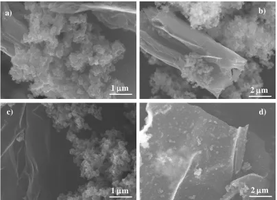
Figure 3. SEM images of the PPy/GO composites: a) PPy/GO composite with 0.0375 g GO, b) PPy/GO composite with 0.075 g GO, c) PPy/GO composite with 0.12 g GO and d) PPy/GO composite with 0.18 g GO.
Moreover, this kind of hierarchically structured feature favors ion migration, which increases the active interface of PPy. However, with an increase in the addition of GO to the composite from 0.075 g to 0.18 g, the distribution of PPy on the surface of GO becomes increasingly discrete, as shown in Fig. 3b-d. Figure 3d shows the SEM image of the PPy/GO composite with 0.18 g GO, where the pyrrole monomer is evenly distributed on the surface of GO. A large amount of GO addition to the composite could provide sufficient attachment positions for pyrrole polymerization, which leads to the discrete distribution of PPy and inhibits the formation of an interconnected conducting path, which increases the electron-transfer resistance and lengthens the carrier transfer path, thus reducing the conductivity of the composite. The microstructural properties of the composites could reasonably explain the difference in their conductivity.
3.4. Capacitance of the PPy/GO composite
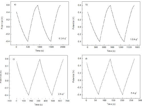
The PPy/GO composite with the highest conductivity was chosen to examine the capacitance of a supercapacitor electrode. The charge/discharge performance of the composite was tested using a three-electrode system. The galvanostatic charge/discharge curves of the sample are shown in Fig. 4.
a)
1 m
b)
2 m
d)
2 m c)
[image:6.596.101.505.130.421.2]
The tested current densities were 0.5 Ag-1 (Fig. 4a), 1 Ag-1 (Fig. 4b), 2 Ag-1 (Fig. 4c) and 5 Ag-1 (Fig. 4d); the tested time differences (t) were 7 s, 28 s, 395 s, 184 s and 69 s; and the tested potential differences were 0.8 V, 0.93 V, 0.92 V and 0.89 V. The calculated specific capacitances of the samples were 455 Fg-1, 424 Fg-1, 400 Fg-1 and 388 Fg-1, using the values of t and V obtained from Fig. 4. The specific capacitance (Cm) was calculated using the following formula:
m
i t t
C I
m V V
(1)
where i is the charge/discharge current (A), I is the current density (Ag-1), t is the discharge time (s), V
[image:7.596.52.549.236.605.2] is the potential change during discharge (V) and m is the quality of the composite in the electrode.
Figure 4. Potential of the PPy/GO composite over time under different current densities: a) 0.5 Ag-1, b) 1.0 Ag-1, c) 2.0 Ag-1 and d) 5.0 Ag-1.
performance. Furthermore, a synergistic effect between GO and PPy also contributed to the excellent electrochemical properties of the composite. Thus, the PPy/GO composite has a good microstructure to achieve high capacitance.
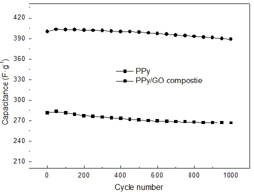
[image:8.596.157.411.371.563.2]The cycle stability of the composite and PPy prepared by the same method were tested under a current density of 2 Ag-1, as shown in Fig. 5. According to Fig. 5, the discharge performance of the PPy/GO composite remained stable even after 1000 cycles, and the specific capacitance loss was only 3.47% (decreased from 400 Fg-1 to 389 Fg-1), while the specific capacitance of PPy decreased from 281.2 Fg-1 to 266.4 Fg-1, the capacitance loss was 5.87% under the same condition, demonstrating that with the help of GO, PPy/GO composite electrode presented a better cycle performance. Not only that, the cycle stability of the PPy/GO composite electrode was also better than that of PPy/rGO nanoscrolls, the capacitance loss of which was over 12% after only 200 cycles, though it is with a high initial capacitance of 667 Fg-1[28], indicating that PPy/GO composite material was with even better cycle stability than PPy/rGO or PPy/graphene as the electrode of supercapacitors. The superior cycle stability of the PPy/GO composite should be attributed to GO which provided the pyrrole monomer with a fixed position for polymerization and effectively inhibited the capacitance attenuation maybe caused by the microstructural damage of PPy.
Figure 5. Cycling performance of the PPy and PPy/GO composite under a current density of 2 Ag-1.
4. CONCLUSIONS
1 Ag-1, 2 Ag-1 and 5 Ag-1, respectively. The superior capacitance and excellent cycle stability demonstrate that the PPy/GO composite has a promising future for application in supercapacitors.
ACKNOWLEDGEMENT
This work was supported by the Heilongjiang Provincial Natural Science Foundation (B201416) and the Scientific Research Starting Foundation for the Returned Overseas Chinese Scholars, Heilongjiang Province.
References
1. A.C. Forse, C. Merlet, J.M. Griffin, C.P. Grey, J. Am. Chem. Soc., 138 (2016) 5731. 2. M. Cakici, K.R. Reddy, F.A. Marroquin, Chem. Eng. J., 307 (2017) 151.
3. V Aravindan, W Chuiling, M.V. Reddy, G.V.S. Rao, B.V.R. Chowdari and S. Madhavi. Phys. Chem. Chem. Phys., 14 (2012) 5808.
4. P. Pattananuwat, D. Aht-ong, Electrochim. Acta, 224 (2017) 149.
5. M Lazzari, M Mastragostino, A.G. Pandolfo, V. Ruiz and F. Soavi J. Electrochem. Soc., 158 (2011) A22.
6. J.D. Strenge-Smith, A Guethner, J Cash, J. Electrochem. Soc., 157 (2010) A298. 7. L.M. Dai, D.W. Chang, J.B. Baek, W. Lu, Small, 8 (2012) 1130.
8. X. Du, L. Wang, W. Zhao, Y. Wang, T. Qi and C.M. Li, J. Power Sources, 323 (2016) 166.
9. G.Q. Zu, J. Shen, L.P. Zou, F. Wang, X.D. Wang, Y.W. Zhang and X.D. Yao, Carbon, 99 (2016) 203.
10. L.L. Zhang, X.S. Zhao, Chem. Soc. Rev., 38 (2009) 2520. 11. E. Frankowiak, Phys. Chem. Chem. Phys., 9 (2007) 1774. 12. P. Simon, Y. Gogotsi, Nat. Mater., 7 (2008) 845.
13. G.A. Snook, P. Kao, A.S. Best, J. Power Sources, 196 (2011) 1. 14. G. Wang, L. Zhang, J. Zhang, Chem. Soc. Rev., 41 (2012) 797. 15. Q. Meng, K. Cai, Y. Chen, L. Chen, Nano Energy, 36 (2017) 268.
16. Y. Chen, W. Ma, K. Cai, X. Yang and C. Huang, Electrochim. Acta, 246 (2017) 615. 17. J. Huang, K. Wang, Z. Wei, J. Mater. Chem., 20 (2010) 1117.
18. Y. Song, J.L. Xu, X.X. Liu, J. Power Sources, 249 (2014) 48. 19. V.H. Pham,T. Gebre, J.H. Dickerson, Nanoscale, 7 (2015) 5947.
20. J. Zhu, T. Feng, X. Du, J. Wang, J. Hu and L. Wei, J. Power Sources, 346 (2017) 120. 21. Z. Chen, W. Liao, X. Ni. Chem. Eng. J., 327 (2017) 1198.
22. C.J. Fu, G.G. Zhao, H.J. Zhang, S Li, Inter. J. Electrochem. Sci., 8 (2013) 6269.
23. Z.L. Mo, D.D. Zuo, H.Chen, Y.X. Sun and P. Zhang, Chinese J. Inorg. Chem., 23(2) (2007) 265. 24. J.H. Liu, S.L. Zhang, M. Yu, J.W. An and S.M. Li, J.Inorg. Chem., 28(4) (2013) 403.
25. D.C. Marcano, D.V. Kosynkin, J.M. Berlin, A.Sinitskii, Z.Z. Sun, A. Slesarev, L.B. Alemany, W. Lu and J.M. Tour, ACS Nano, 4(8) (2010) 4806.
26. Z.H. Chen, W.F. Liao and X.Y. Ni, Chem. Eng. J., 327 (2017) 1198.
27. C.J. Fu, S. Li, C.L. Song, L.L. Liu and W.L. Zhao, Acta Mater. Compos. Sin., 33 (2016) 572. 28. P. Atri, D.C. Tiwar and R. Sharma, Synth. Met., 227 (2017) 21.