i DESIGN OPTIMIZATION OF EXTERNAL COOLANT FILTER
FOR METAL MACHINING MACHINE
AIMADUDDIN AZFAR ABD. BASHIR
A report submitted
in fulfillment of the requirements for the degree of Bachelor of Mechanical Engineering (Hons)
Faculty of Mechanical Engineering
UNIVERSITI TEKNIKAL MALAYSIA MELAKA
ii SUPERVISOR’S DECLARATION
I have checked this report and the report can now be submitted to JK-PSM to be delivered back to supervisor and to the second examiner.
iii DECLARATION
I hereby declare that the work in this thesis entitled “ Design Optimization of External Coolant
Filter for Metal Machining Machine” is my own except for summaries and quotations which
have been duly acknowledged. The thesis has not been accepted for any degree and is not
concurrently submitted in candidature of any other degree.
Signature: ………..
Author: AIMADUDDIN AZFAR B. ABD. BASHIR
iv DEDICATION
To Ibu and Ayah, I did my very best and I hope I make you proud.
v ACKNOWLEDGEMENT
I would like to express my heartfelt appreciation to my supervisor Mr. Febrian bin Idral
for giving me this opportunity to conduct and complete my final year project. He never
hesitated to give me advice and guidance whenever I was confronted by problems.
Furthermore, I am extremely thankful for his patience and advice while leading me in this
project.
I would also like to express my gratitude for my parents for their undying support be it
in terms of moral and financial. Words will never be enough for me to portray my gratitude
and love. Aside from that I would also like to thank my lecturer for design optimisation, Dr.
Faiz Redza for his guidance on the topic itself.
Lastly, I would like to express my appreciation to Panasonic Air Conditioning (M) Sdn.
Bhd, Mr. Hasanul Sazali for their comment and assistant on the study as well as for providing
vi ABSTRACT
Machining has been one of the fundamental processes in engineering when it comes to
metal processing as well as product forming. Machining process can be briefly described as
the process of removing material from a work piece. This study focuses on designing and
optimising the selected design of an external coolant filter for metal machining machine. The
use of coolant in metal machining process is to obtain a higher quality surface finish. Without
proper handling of the coolant in use, the workpiece may even be damaged. The design of the
external coolant filter was made in reference to an existing product. In order to prevent this
from happening, analysis had been done. By using thermal equilibrium concept, the
temperature can be controlled. Aside from that, particle size during machining process was also
vii ABSTRAK
Proses pemotongan menggunakan mesin merupakan salah satu proses terpenting di
dalam proses yang melibatkan pemprosesan besi dan juga pembentukan produk. Proses ini
boleh dinyatakan sebagai proses membuang bahagaian dalam bentuk serpihan berskala kecil
dari bahan yang diproses. Kajian ini memfokus pada mereka bentuk dan mengoptimumkan
rekaan tersebut bagi kegunaan mesin pemproses besi. Penggunaan penyejuk dalam proses
tersebut adalah untuk mendapat kualiti pemprosesan yang lebih tinggi. Tanpa pengendalian
penyejuk yang betul, bahan yang diproses juga berkemungkinan untuk rosak dari proses.
Rekabentuk penapis tersebut dibuat dengan rujukan dari produk sedia ada. Bagi mencegah
kerosakan dari berlaku, analisa telah pun dilakukan. Dengan mengaplikasikan konsep
kesamaan termal, suhu sejuk penyejuk dapat dikawal. Selain itu, saiz serpihan yang terhasil
dari proses tersebut juga telah diambil kira sekaligus menentukan media penapis yang terbaik
viii CONTENT PAGE DECLARATION ii DEDICATION iv ACKNOWLEDGEMENT v ABSTRACT vi
ABSTRAK vii
TABLE OF CONTENT viii
LIST OF FIGURES LIST OF TABLES LIST OF SYMBOLS
LIST OF ABBREVIATIONS
xi xv xvi xvii CHAPTER
1. INTRODUCTION 1.1 Background 1.2 Problem Statement
1 2
1.3 Objective Study 3
1.4 Scope Project 3
1.5 Methodology View 4
2. LITERATURE REVIEW
2.1 Introduction to Literature Review 5
2.2 Metal Machining 5
2.3 Coolant Use in Machining Processes 2.3.1 Properties and Types of Coolant
7
7 2.4 Coolant Filter
2.4.1 Types of Filtration Mechanism 2.4.2 Coolant Filter Positioning
9 9 11
ix 2.5.1 Basic Principles of Sedimentation 12 2.6 Basic Heat Transfer Mechanisms
2.6.1 First Law of Thermodynamics
2.6.2 Heat Transfer Mechanism in Solid Fin 2.6.3 Heat Transfer Mechanism in Tubular Frame 2.6.4 Theoretical Fin Efficiency
13 13 13 14 15 2.7 Selection Method
2.7.1 Pugh Selection Method 2.7.2 Concept Scoring
2.8 Material Consideration and Selection 2.8.1 Copper Types and Properties 2.9 Room Temperatures in Malaysia 2.10 Vortex Tube
3. DESIGN SPECIFICATIONS
17 17 18 21 21 23 24
3.1 Introduction 26
3.2 Product Design Specifications 3.2.1 External Filter Parameter
3.2.2 Vertical and Horizontal Chamber 3.2.3 Filtration Media
3.3 Cooling Fins and Tube Materials 3.3.1 Maximum Service Temperature 3.3.2 Thermal Conductivity of Material 3.3.3 Melting Point
26 26 27 29 30 31 32 33 4. METHODOLOGY
4.1 Introduction
4.2 Literature Research 4.3 Concept Design
4.3.1 Morphological Chart
4.3.2 Conceptual Design of Extenal Coolant Filter 4.3.3 Pugh Selection Method
x
4.4 Three Best Concept 44
4.5 Detailed Drawing 45
5. RESULTS AND DISCUSSIONS 5.1 Introduction
5.2 Analysis of Conceptual Design
5.2.1 ANSYS Result on Heat Flow Analysis 5.2.1.1 Concept 3 Analysis
5.2.1.2 Concept 4 Analysis 5.2.1.3 Concept 5 Analysis 5.2.2 Result Analysis
5.3 Choosing Conceptual Design
49 49 49 51 52 54 56 58 61
5.4 Filter Media Size Selection 62
5.5 Design Optimization
5.5.1 Summary of Temperature Drop
63 66
6. CONCLUSION 62
6.1 Conclusion 67
6.2 Recommendation 68
xi LIST OF FIGURES
FIGURE TITLE PAGE
2.1 Straight turning motion 6
2.2 Cutting process by turning 6
2.3 Slab milling process 6
2.4 Milling motion 6
2.5 Mechanism of particle capture 10
2.6 Conduction through a cylindrical wall 15
2.7 Heat exchanger with plate fin 15
2.8 Rating for relative performance 18
2.9 Properties of Cold Rolled Copper 20
2.10 Thermal properties of copper vs. stainless steel 21
2.11 Working Mechanism of a vortex tube 22
2.12 Summary of temp. drop for vortex tube cold outlet and
pressure rise for hot outlet based on cold fraction
xii 3.1 Fracture toughness (Pa.m^0.5), Maximum Service
temperature
28
3.2 Thermal conductivity vs Price per kg 29
3.3 Melting point of material in Celsius vs. price per kg in MYR 30
4.1 Concept 1 35
4.2 Concept 2 35
4.3 Concept 3 36
4.4 4.5 4.6 4.7 4.8 4.9 4.10 4.11 4.12 Concept 4 Concept 5
Concept 5, 4 and 3 arranged based on rankings starting from
left
Detail drawing of concept 5 in isometric view
Detail drawing of concept 5 with outline
Detail drawing of concept 4 in isometric view
Detail drawing of concept 4 with outlines
Detail drawing of concept 3 in isometric view
Detail drawing of concept 3 with outlines
37 37 39 40 40 41 41 42 42 5.1 5.2 5.3 5.4 5.5
Air and coolant flow direction for concept 3,4 and 5
respectively
Sample of an ANSYS analysis
Coolant inlet temperature set at 27 ℃
Corresponding coolant outlet temperature of 25 ℃
Air inlet temperature set at 22 ℃
44
45
46
46
xiii 5.6 5.7 5.8 5.9 5.10 5.11 5.12 5.13 5.14 5.15 5.16 5.17 5.18 5.19 5.20
Corresponding air outlet temperature of 25 ℃
Coolant inlet temperature set at 27 ℃
Corresponding coolant outlet temperature of 25.05 ℃
Air inlet temperature set at 22 ℃
Corresponding air outlet temperature of 25 ℃
Coolant inlet temperature set at 27 ℃
Corresponding coolant outlet temperature of 26.5 ℃
Air inlet temperature set at 22 ℃
Corresponding air outlet temperature of 24.7 ℃
Temperature in for selected conceptual design against
temperature out for coolant
Temperature out against temperature in for air
Temperature out against the mass flow rate
Distribution of particle sizes (left) and the frequency of
occurrence of certain particle sizes (right)
Comparison of coolant temperature between optimised results
with previous result for concept 4
Comparison of air temperature between optimised results with
previous result for concept 4
xiv LIST OF TABLES
TABLE TITLE PAGE
Table 2.1 Concept Scoring 19
Table 3.1 Dimensioning for reference products 25
Table 3.2 Vertical chamber high pressure filter specifications 26
Table 3.4 Horizontal Chamber High Pressure Filter dimensions 26
Table 3.5 Filtration media dimensioning with particle size
tolerance
27
Table 4.1 Morphological chart for external coolant filter 33
Table 5.1 Table on Summary of Coolant Temperature Reduction 55
xv LIST OF SYMBOLS
𝑄̇𝑐𝑜𝑛𝑣 - Convection Energy
Ƞ𝒕𝒉 - Efficiency
℃ - Degree Celsius
As - Surface area through which convection takes place
E - Energy
h - Convection heat transfer in W/m2. C
K - Thermal conductivity of material
Kg - Kilogram
L - Length
r - Radius
T∞ - Surrounding temperature
xvi LIST OF ABBREVIATIONS
AiRTX - Air Research Technology Company
ANSYS - Analysis of System Software
ASTM - American Society for Testing and Materials
CAD - Computer Aided Drawing
xvii LIST OF APPENDICES
APPENDIX TITLE PAGE
A Gantt Chart for study 73
B1 Detailed drawing of concept 3 74
B2 Detailed drawing of concept 4 75
1 CHAPTER 1
INTRODUCTION
1.1 Background
Machining has been one of the fundamental processes in engineering when it comes to
metal processing as well as product forming. Machining process can be briefly described as
the process of removing material from a work piece which includes the process such as cutting,
grinding, honing and drilling by using machine tools in order to obtain the desired shape. In
high-speed machining, the most dramatic increase in applications are detected to be in the
manufacturing of aluminium components at which the volumetric material removal rates can
be extremely high which approaches thousands of cubic centimetres per minute (Davis and
Burns,2001). Generally, every process of machining for example cutting process is the result
of dynamic interactions between 3 elements which are present during the process which is the
machine tool, the cutting tool as well as the work piece (Balachandran, 2001).
Extensive research on machining was made and it was discovered that these processes
are affected by static and dynamic effects which causes the machining system to deviate from
the desired geometry. Some of the factors contributing to these effects includes slide speed
variations of chips formed and stick-slip friction of the chips (Balachandran, 2001). In order to
2 problems were reduced by the application of coolant in machining process. Coolants functions
as cooling and lubrication system in machining processes, as well as improving the surface
quality of the work piece by constantly removing fine chips from the tool and the cutting zone.
Coolants also helps in prevention of the chips to be welded on the cutting tool which in time
will affect the surface quality (Childs T et. al, 1988).
In general, a coolant flows from the reservoir to the pipelines within the machinery and
then through pipes in the working space of a machine which it will execute the cooling
processes and then reabsorbed into the reservoir via sinkhole in the workspace. That being said,
the chips which were swept away from the work piece and the tool will flow alongside the
coolant into the reservoir. Coolants shows signs of contamination when it turns brown. In
machineries which uses coolant, most often the cause to the colour change is deep within the
reservoir at which sludge starts to form. This dissertation discusses on a design which will
elongate the life time of a coolant within a machine by the use of an external filter
1.2 Problem Statement
A metal machining machine was running for 24 hours a day for Panasonic Air
Conditioning Malaysia Sdn. Bhd. in order to achieve the target production rate per day. The
parts which were processed was in variety of shape and undergoes different processes. Some
undergoes drilling while some undergoes milling and lathe process. A few examples of these
parts are the cylinder, piston as well as the upper and lower bearing of an air conditioner
compressor. Often companies tend to maximize the capabilities of each machine in order to be
cost effective. As the machines are running non-stop, the contents of the coolant used becomes
3 of the finishing of the product as well as the tool life. Most of the machines used are back dated
and roughly aged in between 20 to 10 years old. The pre-installed filter on the machines were
not able to filter contaminants thoroughly which then results in formation of metal sludge. This
leads to high cost consumption on maintenance. The challenge then comes on keeping the
coolant at optimum level in order to elongate the tool life while producing high quality product
finish. This dissertation discusses on design optimization of the current filter at which the
outcome of this research is targeted to be an external stand-alone filter which is able to filter
the coolant flow thoroughly and at the same time reduces heat level of coolant flow.
1.3 Objective Study
1. To design an external stand-alone type external coolant filter for a 24 hours working
machine
2. To ensure the reduction in temperature of the coolant up to 5%
1.4 Scope Project
1. To design and develop a 3D solid modelling of the overall system of the external
coolant filter by using CAD software such as CATIA V5R20.
2. To optimize the design of the external filter and system in order to gain the most
optimum performance by reducing heat
4 1.5Methodology View
In the initial stage, this project which is design optimization of external coolant filter
for metal machining machine was studied on the basis of coolant flow in a metal machining
machine. This later on move to the effect and importance of coolant usage when machining
metals. Then the design specifications of the external coolant filter which includes the size,
flow process and material selection is determined with reference to an existing product. These
specifications should be followed for safety, precaution and hazard purposes. This project then
proceeds to the construction of 5 conceptual designs according to the project’s requirement as
well as the filter’s criteria. The proposed design was then evaluated by using Weighted
Selection Method, followed by the matching of parts by using Pugh Selection Method in order
to produce 3 best designs. These designs are then converted into 3-Dimensional models by
using CATIA V5 R20 software. Considering the flow and the temperature of the coolant in the
machine, the temperature drop effectiveness of the filter is analysed by using ANSYS software.
The same thing is done for the flow of coolant within the designed filters as whole. Finally
with reference to the analysed results, the best design was selected and improvised in order to
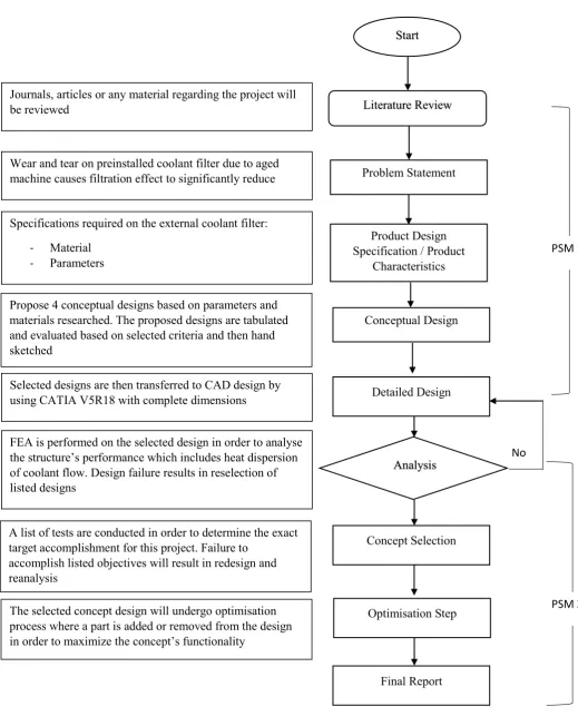
5 Figure 1.1: Overall project flowchart
Start
Literature Review
Problem Statement
Product Design Specification / Product
Characteristics Conceptual Design Detailed Design Analysis Concept Selection Final Report Journals, articles or any material regarding the project will
be reviewed
No Wear and tear on preinstalled coolant filter due to aged
machine causes filtration effect to significantly reduce
Specifications required on the external coolant filter:
- Material
- Parameters
Propose 4 conceptual designs based on parameters and materials researched. The proposed designs are tabulated and evaluated based on selected criteria and then hand sketched
Selected designs are then transferred to CAD design by using CATIA V5R18 with complete dimensions
FEA is performed on the selected design in order to analyse the structure’s performance which includes heat dispersion of coolant flow. Design failure results in reselection of listed designs
A list of tests are conducted in order to determine the exact target accomplishment for this project. Failure to
accomplish listed objectives will result in redesign and reanalysis
The selected concept design will undergo optimisation process where a part is added or removed from the design in order to maximize the concept’s functionality
PSM 1
[image:22.595.50.570.68.721.2]6 CHAPTER 2
LITERATURE REVIEW
2.1 Introduction to Literature Review
This section explains the literature review of metal machining issues which are related
to surface finish in general. This later on moves to coolant issues in industrial manufacturing
sectors revolving around filtering and flow systems in a coolant filter. The explanation
continues to the process of designing and flow analysis of the filter by generation and
evaluation of the designed concept. The source of information and data was collected from
various sources which includes academic journals, produced product specifications as well as
books.
2.2 Metal Machining
Metal machining is one of the processes categorised under machining. It is a process
where metal raw piece of materials are removed or cut into a desired geometry by a controlled
material removal. These processes are nowadays known as subtractive manufacturing. The
“controlled” term used in the definition is a variable which are controlled by many factors
7 feed removal rate. There are however other methods which are used in order to process selected
raw metals such as flame cutting and plasma cutting. Generally there are 3 types of metal
machining which are widely used until today. These classifications include turning, milling
and drilling while other operations can be considered as miscellaneous or as a sub category
from the main 3 processes including shaping, boring, planning, broaching and sawing. Going
through the 3 processes stated; turning processes are operations where the workpiece are
rotated in order to remove materials. Millings however are operations which contradicts
turning. In milling the tool rotates against the workpiece while drilling is an operation of
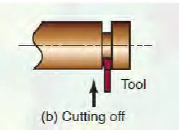
producing holes or refining them by using rotation cutter tool. Figures below shows some
common machining processes.
Figure 2.1: Straight turning motion Figure 2.2: Cutting process by turning
Figure 2.3: Slab milling process Figure 2.4: Milling motion
(Source: Chockalingam, P., Kuang, K. C., & Vijayaram, T. R. (2013))
Nowadays, instead of being manually steered, materials are often processed in an
[image:24.595.372.502.367.461.2]