l
AND COMPOUNDS OF SULPHUR
A thesis submitted for the degree of Doctor of Philosophy
in the
AUSTRALIAN NATIONAL UNIVERSITY by
LORIN L. HAWES
The work reported in this thesis was carried out under the supervision of Professor A.N. Hambly in the Department of Chemistry, School of General
studies, of the Australian National University. The research project began primarily as an investigation of mixed sulphur-selenium ring
comp-ounds, but as it progressed, this topic was soon eclipsed in importance by two of the tools developed along the way, the low angle coaxial camera and the SnI
4.2SS lattice.
In reporting this work, I have attempted as closely as possible to arrange the various topics in their proper chronological sequence. The first chapters deal with the development of the coaxial technique, followed by its application to showing the existence of certain cyclic interchalcogen compounds. Chapters five and six present a study of the SnI
4.2SS lattice and the use of this, in conjun-ction with the coaxial technique, in showing the existence of other cyclic interchalcogen compounds.
Two instruments, the gnomonic projector and the conical coaxial camera, which were developed in the course of the work but which were not used in the research reported in other sections are described briefly in chapter seven.
In arranging the material in this theSiS, all of the figures, except for minor sketches, are placed at the end of each chapter, followed by the plates.
I wish to thank Mr B. Chappell and Mr K. ill-iams of the Geology Department of this University for their kind assistance in obtaining coloured
I
TABLE OF CONTENTS
CHAPTER ONE
DIFFICULTIES IN MEASURING LATTICE PARAMETERS FROM LOW ANGLE REFLECTIONS
CHAPTER T 0
THE DEVELOPMENT OF AN ACCU RATE LO ANGLE
i
CAMERA -5
Theoretical considerations 5
Practical considerations 9
Film measurement and film shrinkage 9 Specimen thickness and absorption i i
Line breadth 11
Errors due to camera construction and alignment
Camera construction and use
CHAPTER THREE
INTERPRETATION OF THE COAXIAL DIFFRACTION
14 14
RECORD 25
Calibration and film measurement 25 Conversion of Z values to other functions
and the correlation of coaxial films with
oscillation, rotation, and related diagrams 29 Treatment of data to minimize the effects
of random errors 30
Selection of lines to be used 33
CHAPTER FOUR
SOLID SOLUTIONS IN THE ORTHORHOMBIC SULPHUR LATTICE OF SULPHUR-SELENIUM AND
SULPHUR-TELLURIUM COMPOUNDS Preliminary work
General scheme for the measurement of
37 37
lattice parameters of a-sulphur solid solutions 39 Solid solubility of SeS in a-sulphur 43 Investigation of the mixed molecules 45 Solid solubility of Se
4S4 in a-sulphur 46 Solid solubility of se
Molecular weight and chemical analysis of Se 2
s
6 54 Solid solution of tellurium in the a-sulphurlattice 55
SUmmary of results of the solid solution
studies in a-sulphur 57
CHAPTER FIVE
COMPOUND FORMATION BETWEEN SULPHUR AND
STANNIC IODIDE 62
Monoclinic SnI
40 2S8 66
GeI402S8 67
X ray investigation of orthorhombic SnI402S8 67 Determination of cell size and space group 68 Placement of heavy atoms in the unit cell 70 Placement of the sulphur atoms in the unit cell 74 Twinning and the false unit cell 79
Discussion of structure 81
CHAPTER SIX
COMPOUND FORMATION BETWEEN STANNIC IODIDE AND CYCLIC INTERCHALCOGEN COMPO UNDS
Evidence for the existence of SeS7
X ray study of SnI402SeS7: experimental Exposure technique
Structure determination: preliminary consideration
a ysis of oscillation films
Further study of sulphur crystals containing tellurium
Determination of TeS7 in a-sulphur solid solution
CHAPTER SEVEN
THE GNOMONIC PROJECTOR AND THE CONICAL COAXIAL CAMERA
The gnomonic projector The conical coaxial camera
REFERENCES APPENDICES
93 93 94 96
97 98
105
107
113 113 115
i
CHAPTER ONE
DIFFICULTIES IN MEASURING LATTICE PARAMETERS FROM LOW ANGLE REFLECTIONS
The lattice parameter changes which accompany substitutional solid solution in crystals have been studied extensively in the cases of many alloy and mineral systems, and on the basis of the proportion-ality between the solute concentration and these lattice parameter changes highly refined analytical techniques have been developed to measure the limits of solid solubility in such systems. (1)
Although straig tforward in cases involving crystals of high symmetry and high lattice energies,
1
the general method has generally proved unsatisfactory when applied to lattices of low symmetry, espec1ally those in which the cohesive forces are small. In such cases the difficulty is not attributable to any inherent failure of the principles behind the method but rather to the difficulties in the accurate measure-ment of the lattice parameter changes. In the case of a typical cubic metal lattice, for example, each line on the X ray powder diagram can yield the single
lattice parameter a
o' and, due to the small magnitude of thermal effects, it is possible to record ell resolved Ka
1 and Ka2 diffractions in the back reflect-ion regreflect-ion of the diffraction geometry here systematic errors are very small and can be effectively eliminated by well established extrapolation
teChniques(2,3~
thus leading, without undue difficulty, to lattice parameters reliable to four significant figures.Practically all solid solubility studies undertaken by X ray means have involved highly symmetrical lattices which yield diffraction lines in the high angle region
of the diffraction geometry. Unfortunately, only a
small proportion of crystalline substances have lattices of this type. In the case of the lattice of a typical van der aals solid such as sulphur, the situation is
quite different. Thermal effects tend to ruin the sharp-ness of high angle reflections, and the small size of
reliable indices to many of the reflections which are recorded. For those reflections w ich can be used, more than one line is usually necessary to determine a single lattice parameter, since, in t e case of an orthorhombic lattice such as that of sulphur, whose space group is
Fddd(4~
the position ofeac
~
!
reflection is affected simu taneously by a ,b , and c it it is0 0 0 of the type hkl; by ao and b
o if it is of the type hkO, and so forth. Reflections of the type hOO, OkO, and 001 could be used to measure the individual lattice para-meters independently, but reflections such as these are relatively rare tor space group reasons and pro-duce reflections strong enough to register on powder diagrams only in exceptional cases. Several
reflect-ions are theretore usually required for the determin-ation of a single lattice parameter, and the data for the positions of the diffraction traces must be combined by the method of least squares(5)or by some other pro-cedure hich resolves the various d spacings into their components of ao,b o ' and co'
Any random error involved in the measurement of line positions on the film will affect the various
lattice parameters differently depending upon .the indices of the planes involved, and if the diffraction charac-teristics ot the substance are such that the usable lines have, typically speaking, low h indices, medium k indices and large I indices, then it is likely that a
o will be determined with a precision less than that for b
o' and in turn the latter will be determined ith a precision less than that for co'
Partly as a result of these difficulties, research into the structures and properties of solid solutions involving low sym~etry solids, especially of the van der aals type, has lagged behind other fields of
research in structural inorganic chemistry. Virtually all solid solution studies in inorganic chemistry have been concerned with ionic compounds, and the solid solution behaviour involving small molecules has become a largely unexplored area of research.
3
th cifficulties encountered in tIe study of l1ixed eryetal systells of low lattice sy .. etry: in this study i t , as desired to determinc the ~olu
bility Ii its of the I~r .olccules in the arent iocline and bromine lattices and to detect any polar orientation effccts, using conventional record-in~ techniques and a modified least squares nethod of calcu ation. ilthough the survey of the system
waf! done as car fully as po~sible, and although thc results Drovided valuable inforillation, they left
luch to be resire~.
It pa~ cstablisl1c( that there ':as a sharp breac re1re~cltin~ the IiI i t of solubility of IBr in the brol'ine lattice , as observed on the cell volume vs. co Iposition curve, that there ~T2.S a t'lo-nllase
rcgi on in HId cll t '.e lattice parn..lCters reI minea constant ''lith cl1an""ing co positioll, followed by a second single- lhase region in which the lattice parameters clanged '\:i t; changing co: osi ti 011.
These results, in conjurction ' .... ith otiler evicence sup)orted the vie~ t:at the lattice in t' e vicinity of tile equiator.,ic cO.1)osition ",as inc'eed esse~tially different fro .. , t!le lattices of ioaine and of bromine.
Tl c u ner bre"l..(s in t.le lattice ara~!eter vs. co ~osition curve pere not observec horrever, wId t e fi LIS \;'ere C"eneral1y of oor ('Iuali ty , being
notty and having a high scatter bacl~ground , so t wt i t \. a" i ossi ble to rna e reliable intenei ty
esti .ates to provide more c.:.efi 1i te evidence concern-ing t: e snace group of t:.e IBr lattice.
The illdivi ual lattice arameter~ shm'."ec a cOlsiCerable fluctuation of axial ratios , rJuch
ore t 'an :t learec. reasonable to eJ ect fro .. l
sa,. Ie to c-ample , an nuoillore tll1lIlIa been observed in arallel stuc'icC' of tl.e coefficients of e::rpc> .. nsions
of I I re it... logens (~ , g) <ll1d i t
,~'as
c onc luued tJl< t thi s ,"as ~uc at least )Qrt y to slight variations intl c (ifferent gla~s Cu. illary tubes which enclose the P:t les in t c for er case1 but not in t .e latter cases, ,~ri ere al I.Cl1SUrelJents were ma e \'i tIl t.1
SFl.mc c i l I a r y tube .
mother,e unlly serious , source of error was
of El random nature: t: e variable of ~cct of t'le
inevitable lac~ of accuracy in reading the position of the diffraction line on the film. All of the
reflections recorded in the iodine-bromine study were 10Yl aJ glc ref1 ecti ons, lying in tile range
&= 12 0 to &= 320. It ~as found in practice to be
i p08Pibie to rea t~e line ~osition ore ~recisely than to t 1e nearest .1 mill, an tILis corres onds , at &.= 200 , vrith tlle camcra useG , to a relative error of Ell roxil ote1y . 2~ for each lattice ara eter, or
• 6~ for tile uni t co 11 vo lume. Be cause of Lle large variation in resolution with changin0, & in the
lov angle region, tIle e ... !ect of Llis ram,om error
is iffercnt for every linc and is not eli Ilnated by the least snuarcs treatment.
In viel'l of t!lese nroblems , i t was a Darent : t the outset of t:le "ork rCl)ortcd in tLis thesis
t lot the first difficulty to be overcome ~as that
5
CHAPTER TWO
THE DEVELCPtfENT OF AN CCURATE LO.: TGLE C JERA
Theoretical considerations
The technique of powder diffraction was devised
independently in the United st ates of America by Hull(1)ancJ. in Europe by Debye and
S
C
h
errer(2~
the esc-ential aifference in the t\,O methods bein 6 in the place~ent of the filII 'Wit1I relation to the specimen ... ull' s "!.r~angement consisted of a flat plate nerpcndicular to t' e ray beam so that the diffraction cones from the s ecilen intercepted thefilm as concentric circles, w~ ereas tIle l'ilm in tile Debye-.:Jcherrer arran:;ement ,~'as for:ned as a
circular cylinder whose axis was coincicent ~it~ the specinen, and perpenc:icular to tue l)rimary bea:.}.
T'lis latter arrangement ilas several aG.vantages over the fOl er: tile elltire cJ.if.L'raction record
bet,'een &=00 and &= 900 is recoruec on a single film, tIe s ecimen-to-fil~ distance is constrult t 1 S _ aci Ii ta ting in tensi ty neasure .. en ts , an t. e Brag~ ai;le & corres onding to u given reflection is irectly roportional to t~ie istances bet/een corres onding arcs on the fi lm.
Because of these advantages the iJeoye-Scherrer a1 'a gcment TIn. almost uni vers~lly ac(.;eptea as t~Le hctter metllDd for recoruing o\';der diffr.:lction patterns, an i t las been rcfine~ consi er.:lbly since first i. troduce .
The advu. tage s of ins trullen ts of LIi s type
do lot C1.ply 107 vel' t o t' e recordi g of diffr ction ata in a n alli1er ~ui table for the recise et n in"'tion of lattice ,(r~meters fron 10. sy etry lattices suc 1 as tllOse eati oned in the receding cha!)ter, for tDC ~ ility to r co non e:--istent or un sable
igh ano-Ie re.:'lcctions is of 110 value; inten i t · mC3.surc cnts O.i. the 'if.i.raction recor' are not reauircl , an, t'le very fl.,ct t lat &- is dircctly . ro'')o tiollal to the ist"nce b t,,'cen con'es on'ing
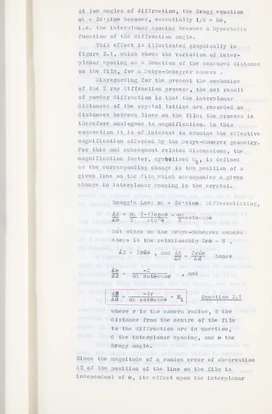
l .. t low angles of diffraction, the Drag;:::> equation n", = 2d' sine becomes , essentially 1/d
=
1{&,i . e. the inter'1lanar s acing becomes a hy crbolic function of the diffraction angle.
[image:11.578.14.558.51.879.2]T is ef:ect is illustrated graplically in figure 2.1, wi:dch shows the variati on of
inter-lanar spacing as a function of the easu~ed distance on the film, for a ebye-Scherrer crulera .
0isregarding for the resent tIle .tlec lani c s of t:le r
ray c'iffraction process, the net result .i ..
of powder diffraction is t .. lat the in tel1llanar distances of the crystal lattice are recorded as
distances bet,.'een lines on the film: tile Drocess is t lCrefore analogous to magnification. In tlis
con~ection i t is of interest to eJ~mine tle ef ective magnification af:ior'e by t e Vebye-Scr rrer geolCtry.
or t is nne;, subscquent relate discussions , the magnification factor , sy::ub lized Ii ' is efined as the corres onding c1 al1ge in tIle 90si ti on of a given line 0 t~.e fill'l which acco::. 3J1ies a given c lange in interylanar spacing in the crystal.
Bragg's Law: n).. = 2d·sine. DiiferentiG.ting ,
ltd
=
;re.
= -~).. cotecsceBut since on t;le ebye-,:,cherrer ca. era there is tile relationshi .. 2r = S ,
J. S
=
2r"-& , and tiSn
4.& -2
ad
=
l1).. cotecsce2rd.e-=
-rcr
, andhe ce
r
£is
_
I
I
~d
- n",c~t~csce
= Mi Equation 2.1where r is the camera radiUS , S the distance from the centre of the film to the if.lraction arc in question, d the int rplanar spacing, and e the Bragg angle.
Since thc nw.gni tudc of a ranc om error of observation
spacing observed for a line is inversely
,ropor-tional to ii ' that is,
.6doc nACOteCSc& r
and since cote and csc& both increase ranidly with decreasing values of 9, t~e error introduced by a given misreading of the true position of a line
will be une ual for every line.
Ideally, random erroJ..s could be minimized
mathematically if they could be equalizea for
7
all lines. This would entail a geometry \ ith a constant
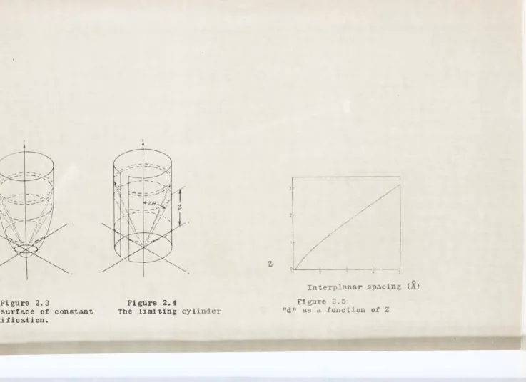
magnification factor. The sha e of such a geometry may be obtained by calculating the values of d
corres onding to various values of e , and
construct-ing a curve on the basis of these values such that
the length of the curve at any point llus a constant
proportional to ~/2 is cirectly ~roportional to d.
This construction is depicted in figure 2.2.
In this illustration, the X ray beam is
imagined to trave 1 fro. left to rigJlt acrosE' the
base line, s tri ';:i b the specill.en (S). The fi 1m
would be 11aced along the curve B, one of a fa ily
of curves of constant magniftication.
If a camera of this type ,lere constructed to the dinensions shmn i the figure , then the
spacing in
R
corl.~esponding to a point on t' e fi 1mat B would be .771 plus the istance B, measured
in inches, if Cu
r
a
X rays were em loyed.1- camera of thi s ty)e however would be di f "i
-cult to fabricate accurately anu. r:ould be sensitive
to sy~te~atic errors due to variations in film
t;lic\:ness, film shrLl~~Q.ge c.nd so forth, and ,;rould
bc Ii 'i te(~ to a Po eci fi cave lellgt 1 of ~r rays. In t 'lre e di e11si ons, the c ondi ti on for
Cons tan t rllUgni:£i c a ti on is seen to be a bu 11 e t-shape' urface OJ. revo lu ti on genera ted by rotating tIle
curve D around tIle line repres en ting t:le X ray
b0.Wl. This is sIlm.n in figure 2.3 .
.1 1 thou 11 t Ii s sur:L'ace ,'[ould bc im racti cal in
use , t e right circular cylind r which is asymp
cffect. There are no restrictions as to uavelength
in this latter case , ane... t" e purface is seen to be easy to fabricate.
In termr' of figure 2.4. a camera constructecl
on thc basis of this geo etry \,lould have t.lle X ray beam coincident Hith the Z e.~is, with the film as a cylinder coa.:ial "Ii th the beam, ane wi tIl the sDecimen at thc origin.
Taking the raCius of the film cylinder as unity, the di stance Z above the
;cr
(s"'1ecin'!en) plane isc qual to cot 2&, :lCnce , <='ubsti tu ting in t 1e Bragg e qun ti on,
=
n,,-2 sin(8.1C cot Z 2
Equation 2.2
The magnification factor for this cylindrical geo,ctry is obtaine~ ac follows:
if"erentia.ting with res ect to & as before,
d
;rz
hence
J.
Z;rcr
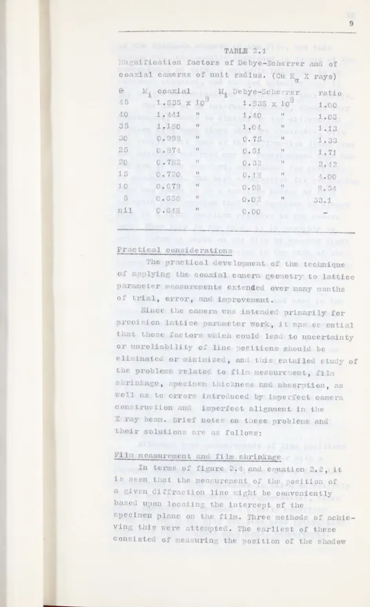
= (n"- cos 3 9) -1 = Mi uqu .... ti on 2. 3Since cos a)"'1roac~es unity as 9 becones small, L1 . a.nroaches a constnnt vc..lue. The relative .... P1uGl1ification factors of ti.le Debye-Scherrer and coa~'ial riln arrangenents are listed in Tcble 2.1 fOl: value<=:' of e les t'1m1 ",50.
It v.'ill be notec:. t:lat the relntive !.H:1gnifica
-tion uc.;.v ,ntng of t. e co "J'ial ~eo-letry becomes (l..) reciable in thc range of 9 values corres)onc'int?; to t.e usnb c reflections of tile low SYI .etry
9
---
..---TABLE 2.1
j a[!;ni:1ication factors of Debye-... cherrer ancl of coaxial camcras of unit radius. (eu T ~C rays)
0:
& 1.i coaxial ' i Dcbye- 'c 1C "er ratio
8
108
Li5 1 .835 x 1 1.335 -"'- 1.00
-0 1. L.!/1
"
1.40"
1. ,., oJ 05 1.180"
1.0"
1.13 00 0.998"
0.75"
1.3325 .874
"
O.G1"
1.712 C.782
"
0.32 112. ~2
15 C.720 11
0.18
"
4.001 0.67.
"
0.08"
'3 • Gi!,5 0.656
"
O. " r:, 11 33.1nil 0 .0;18 11
C.OO
1 ent 0:1 the tecimique
0· ... n, )lyinf, t_ c cOClYial camera geo letry to latticc parameter IlG(1"Urements ytcn eel over many 110nths of trial, error, an' i 1 rovement.
8ilC the c·( era ,2. int nued riuarily for
precision lattice cr,~met r wor'(, i t ~'D,f' ential t' nt t'lOse .Lectors \; lic~ coul' leaLi to uncertainty or unre liabi Ii ty or line o. i ti ons s:.Lould be
eli inateC. or linL.izec.., an" t:_is entailed c::tuc.:" of tHe nroble: s reI tel. to ::'il'l !easure .ent, fiLl
s'.riI:'-agc , .:'lJeci'en t.icm ss and nbsortioll, as
\J 1 a" to crrors introc.:ucea by i
cons true ti on anti im erfee t alignment in the fray JCt:L • ..3rie:.. notee on t~lese proble.ls and t leir solutions nrc as folIous:
J.'iln n t anti fi 1m sllrin:~age
In of figure 2. , e qua ti on 2. 2, i t
is se en t 1[1, t the ~eo.sUJ..~C .. 1Cn t 0':: ti.iC losi ti 011 of
a giv.n ci.L~r~ction line mig~t be convcnicntly bas t.:. u. on lac ;ting t'l€ intercept of the
8peci,en lane on the film. Three !.lethods O:L achie-ving tni,,-, \'Iere at to 1 ... ) ted • rr'l e ealli s t of these
[image:14.587.15.551.13.891.2]of tl e s eci on su ort 011 the i1. , but t1is
ct ou. "ras subs (11.. ntly a 1111 one In f.:lvour 0.1.' t 10
e onvenienee o~ usin'T C'.. sui t<:dJle c:ubst[1nee as an
i It rnal sta ar' , a lel 'a lO,t c..ctually use - in
any 0': t. 0 eter.~i lations 1'0 ortod in t is t"lcsis.
TLe use of an internal sta.daru, tough very
convenient, ten-s to clutter u tde di':" r.:1.ction
... t'::'crn i th ore lines t c 1'2 rc c:08i1'aole, wi t 1 L1C' 'csult t t so. e of tho (iJ._· ... ·actl01 linc8 "'ro
tlC s eci en ateri"'l may be pu 'crio oscd u on t.e
1c:.ttern 0': tuo ~ta.lc., r-: , an ruino' for Ul o~c,
of Jcasu o. ont. The best altelnative for overco ing
this ~7as .1.ounc to bo a s ,eci en 01 'er of suc
accurate con"truction t1at t C ppeci~en is al .:lys
hel' in a fixor' osition relative to t:.e ca, era
) 0 d Y • "e n t hi s i s t' • e c G. ~ e , i t i s 0 S ~ i b 1 e to rint '~iducial . arks on t~.c fi 1 by passin::> Ii'" It or .: rayc t. 1'0 1 : S JaIl holes iLl tIlc si e of tie
C[1I'e1'a bOGY, t cse u.a1':s tlen scrvo pi lultancotlsly
to establis; t 10 s cci .cn osi tion <.. 1 to nroviue
[1 .ean;- ... 01' correctin, for 'il s.lil::ag.
(Thi S W.:1.S t. c . et od. (,;;,' 0 te and sed i 1 t.le
mcU. ~ure lcnts subs que tly J:Ja e on LIC -suI .mr
solie. solutions rcporte in Chapter IV, but in
ore r to c ICC' on thc cons tancy of tue s cci1"on
oritioning ovcr n coursc 0 l.:1.ny e.;:") osurc s , :;>.n i Iternal stc.. 'nrU. i t:1S c.d .ed u.S i:ell. . ft r i t h'" bcen ~ta lis.le' that a constant sneci len DositiOli~g coula in eCL be ailtained, tIe
Q.' 'ition of an interno.l sta 'ard as abancione
('n ti 1'e l~", <.n' t 1e r:cc::.sure'lent c Ie ortecl in
CIa tei-S: c.- VI ,"el~e bc.seG. u)on tLc £i ucial
I"'rl~s alone.)
1 thougl good 'Ie suren en ts 0.1. line pas i ti ons
II y be l]Qc1c 'lit'l a ,li11i 'ctcr 1"'..ll or .itl a
uerger eo.suriIg
cvice(~)it
"as foune t_latt~le
e.t of line pOSitions is &i e ~cctiv ly y the uce of a 1'ccol":'ing I icro hoto cter, . i ce i t i ossiblc to pro ucc a greatly f.lugnifi c
i !l1.gC' 0 tlC fil!, iLl t cline C"u;: intensities
11
Specimen thickness and absorption
Errors in line positions caused by absorption are related to the absorption coefficient of the sample material, and to the size and shape of the sample. In the case of a nominally cylindrical sample as is used in the Debye-Scherrer camera, these errors are due primarily to uneven absorption of the primary beam before it reaches the rear portion of the sample, and to uneven absorption of the diffracted rays before they leave the sample(4~
In principle it is possible to minimize errors of this type in any diffraction geometry by using an extremely thin specimen. This is usually done when the Debye-Scherrer camera is used in lattice parameter work when high accuracy is sought.
Longer exposures are required however, and it often becomes difficult in a mechanical sense to prepare
cylindrical rods which are sufficiently thin to overcome the problem.
One of the main advantages of the coaxial geometry is that it is well adapted to the use of very thin specimens since the sample is most
conveniently prepared as a layer of powder which is suspended on a flat surface, and it is very
simple to attain a sample thickness of less than one thousandths of an inch.
The amount of specimen material which must be traversed by a diffracted beam is proportional, in the case of a flat specimen, to tan29, and hence becomes small at low angles of diffraction, rather than larger, as is the case with a cylinder.
Although it might be expected that absorption errors would increase greatly in the vicinity of
~
=
45? this shift in line position could not exceed the specimen thickness even in the case of a 'totally absorbing' specimen and is there-fore negligible if a thin specimen is used.Line breadth
factor, lloi"!evcr t.lis is t e case only if
measurc .ents 0; e<iual • rccisi on can be ,ad for
all lin c with regar to thcir intensity caks.
This is clearly not LIe casc if somc lines re
e:'trcmely broa , and t'lere i~ a tend ncy tm'ard
t'lis i. t le coa:"i"'l gem etry due to L e acute
a.nelcs at .' .. ich t'le ciif.L racted bcEl. f' stri ':c t e
fil~ . T .. crc are several factors involved in t'is,
,ost l.otographic ':ili1S uced in .l~ ray ":orc
h[we a scnsi t' vc e, mlsi on 011 eac ri e of 0.. fi l;n
be.sc. In tL C casc 0 t e ' .odirc::' fi I. used by
tlC aut:lOr, t e tlic.illes'" oj. t1C .... i l base U1S
foun ... · to iJe • 1') C.l al ' t:1e t ic" .ess of cach
e',u1;.;ion 'm~ fou to be . C G c· ... HC 1 Li e
broa c11ino cause' by tile 'ou Ie c u1sion is
i 11ustr.:1te(J. in L C c.ccor .. anyin c:~etcL.
It is so ,n that the
ovcr~11 brcadt E of
L1e line is four ti es
t e line Dread t'1 on
a si ... gle e ulsion,
as C'u i nl:; t~ c. t t:~c ~i bn
is vic 'ed i 1 L.c .on..al
:mncr, t1at ie , ~er
pel ... ' i Cll luI' to its
sur ace.
In c.:trc "c ca~ es tili s cf :ec t . 'ay leo.a to t 1e
for. "'tiOl1 o~ t' .. o 5C aratc lincs on thc fil~.
In a ition to being un esi a Ie fro the
oint of view of rru1 o. crrore , tIC ioage ror'e~
on t:le er.u sion f.:trt .. cr iro' t.l sucCi"C.l ~.i:!.l
be ·co.:~cr t 12.11 t c i a "c on t' 0 11 a 'er cmulsion,
c' Llis coul intro'uc a systc''1''tic error to
t lC 1 .:ts":i,·C entc:::. :-'O.L~ tJ.1 SC ... ·c .... ons i t is dcsir
-.1. bl c to r nove t 1e outside e .. !U lsi on fro, t lC fi lr •
uril1g roc "'. ino '
.mot. r facto· ~ue to fil claracteristics
,~rilich af ccts line brca t . is thc tC11C!cnc" for
t 10 C mlsion to scatter t 1C bcam an cause
'wi th ot er f' oure s of Ii 11e broadenir '.;, ; er all
bu t the s tron"'e st line s , <.. d i:, una.voi ab Ie in
any case in ... p' oto rai')!~ic £,i 1 1. use'.
13
The ff et of tIC divergence of the iffraet d
)e<:1-- )eco es se ~ious at : ir~1 values of Z because t'ie lar."r neci e -to-fil distance )e it.
a :; ... ~eate1' s )1'oa ilH~ out ti an at 10'.;e1' v2.1ues oj. Z.
Part of tliC' divergence i8 due to t.e inLe1'ent
i "1erfections i1 t Ie lattice of t 1e snecime_
I aterial an Cc 1 ot ;)e controllec , "->ut t e
(iVcr:sellce .. , ie i'" d 1e to t. e ~._.lte s ' ze of
t 1C .: l'ay ')ca a. l to its iver e_ ce can be
co tro lIe" to acivi.. ... n tage.
111c diver~ence of an ra - be .. fro' a
~enerator SUCl as t.e hili s P 1008 use in t~is ','01'" is a fu.etion of t~e c:mglc bet'reen tLe tlbe
tar.3et ·~ce
fil !e!lt ~re
n( tIe bea~. Llectrons ~rom t~e ocuso' electrostatically u on a
rat'ler narro 7 rea of t~c terget, eac I ortion of
.hie acts "s Joint source 0 ... : ra
.
C",
".1 i c 1~re e ' tte i 1 al' direct'ons. ~lC vLri&tioil i
( iver£:;f'l1cc '\ i t 1 ~er;ar to t e angle bet :een .t Ie
i illustrate L ... fi ure
2. G , is ceen t _at t'_e ben :12.S vi'tually
no "iv rgence in . ve -tical irection i : i t is
in tLe tar et, t' oug ~ t ler
is Li pc roSe ce "'i t: il t.e • .:11...e i t"'e L .. .
, e i s [ e 0 f t ' i '" e f ~ e e t :i t 1 re r: to
t_le co ,.:-illl crt era
b:
u ins <M fine "'lit as acolli .2.tor rat 01 t.::1..n t. e 12.1 Cil'Cule.I" 1i ole. .... ssu il1~ t at t 1 narro'l lrular bea e']i ttH"
fr01 tIe fnce 0 t~ e t~rGet i centercG a ( is c o ... ~-ia. '1. t 1 t.e ii 1 eylin er, it 'i 1 L tel.ce t
t~ e ~ eci en :l~ <. line 0 ~ fini t lcu.;t .... "",i raet .r rnys fro.! t:l s eci e 1 '711ic 1 ori ""i .<::.te at t. e centre of t ' i i . ,i 1 stri!~e t.IO "'il. ""s
'l. ~ 1 cl circlc c in snaee) b t t... dif racte r ys ::hi ell ori -ina te 0 )0 i ti ons o~ t~.e line
ot.er tl~~ t e c nt1'e i l l stri e t c ~il a
Ii s , t l .... nes 0_ ". ic: b cO"':C ';o1'e G!1
ore inc line to t'lO ca['l 1'"", (xi S Q. t 1'e tel." v< lues
ovcr tlC lcngtl 0 line ~ll convergc on a >lanc
7 icl i:- nOl..<:'..l to t e lanc 0 : t. c <:: )cci::Icn Cl to
thc lanc 0 tl C ~: ray bea . This causcs a iocusi 19
cct ','lic ro'lCCf' di ~ract:lol1 lincs .. ich arc
cry r arp on t;,'o area" of t·.8 fi 1 1800 apart.
This c;ncct i c i lustr ted in igur s 2.7 an' 2.8.
Error Lue to camera conctruction an' o..lign!'Jcnt Thc f[' bri ca ti o. OJ'> J.
r.
_accurate cylindcr of
con taLt r[l'ius is ~ easy _att ' an p ese ts no
[' ecial roh e
'.0 centerL ~ o~ LIC sli t Fyste is .ore
di ~ 'icult . o~cvc', '1.'" is al 0 t:lC reciC"e t
of t 1e co.' era in t .. e bean. Provic;.c' t at 'casona lc
care i~ tr:.::en 0 t at gro:-s errors a .... c not 1'e ent
i I t:es latv regarr
c-
,
t: C e: .... ects o. e TOl'P 'ueto t
{ vera..Jil
CQ. ses a'C' e li.linat ( readi ly Cor si >ly
t'le o<'itio.l~ 0 .... " :;iven line on C2.C 0
t. e t .. o ·i 11- _ 801veG. are H of t .. e ... i l < i "'ure
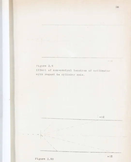
::. illustr"..te t . .le 'is lc:ce ent of th inec- C:ue
to colli " tor (all' hcncc t' irr".. iated ortiop of
t'le :- cci en) ei.~ 0
n::
C .ltre, 0..1 • figure 2.10i luc:t 'atc£' t e L 11acoIilent OoL. ~: C li ef' ~ue to
anic.;.(1v€ 'ten t t i l t o t.eca.lra )0)' it~ re~cct
to t e bca-·. It is ,ecn that i 1 bot 1 cases , L c net
c_ ct i'"' t: at .... r error, LZ, ic~ occurC" 0. one
'" ide 0 n t.le fi 1m -'i 1 a, C' 0 oC'Jur on t Ie ot 1 r si e
, e 11 , )U t i l an 0)';) 0 sit c . ire c t i on . T •• e in Ci i vi
-. e l l i .1 C ::; 0 n e i t C r sid co:: t e f i 1
b cou jcct to ~.i te .atic crrors but t l avera~c or
<'umm . line 0, itions \':ill bc ::'ree 1'0 t' em.
conI] re ['ini sources 0 SYStCi utic error
u to c.:' .cr,-,- con t 111C ti on are t:lOS C invo 1 ving tl e
loc<.tiOl 0 t'eZ=O ositiol.
is cf ccte ei ther b r t' e u e oJ.. [ill internal
"'t.:m arc. , or by carenul con<::truction of tIe SpCCirl n
su ort s'stCl an' its fi t into t c camera body.
built for use in
15
scction. of this t esis. T e first 0 t esc Tias
LIC lexperioental mocell and r:as altc.rec1 eytClF'ively
in tryin!" out ne\, ideas. The ~ cc onG. ca I era \:as constructe on t C basis 0 t.c e. erience gained
fro the u:-,c of t e irst over a erio of L.ree years.
o t:'1 came ras are 0 ap roxima te y t e sa e si Z(; , and
Gl noay t:e general features s.o~n in figure 2.13.
T. c second cam ra is illustrate in plete 2.1.
In use t cameras are neld ii ly in Dlace
on uitable brac et- so tIat t.e colli etor l i t
i s in t.e lane of t.le target of t'.e .. ray tube , or
is as near t o t n t plan e as 0 s i .... 1 e. ::. t e c ace 0 f
th Phili 1 08 generator illust_'cted in late
2.2, i t -"S nec s.ary to alter t_e tubc lolder to
ac:.ieve tl is. .i t . t .e sta. dar fi ttings i t nas
fotn i ossible to obt2.in a bea at an engle less
t an two egrees to t e tar~et DIane. urilli ~ an
: tra !101e in t e filter holder and enlarging the hole through the tube sU1)port enabled c conditi<Jl
of near coplanari ty to be achi eved. .Then i t was Gesired to use filtered radiation, en a pro riate
filter was placed inside the front aperture of the collimator.
Because of t' e l~ck of divergence of the
pri ary beam, i t i s largely i aterial ,-hether the camera i s 11ac d directly against the generator or i s .eld so_e di stance ",:ay. In order to facilitate
alignn ent the c~ . eras ~ere Lounteo. fro. one to t\70 inc lee al7ay fron t e tube nindo", QJ1u oetal s liclds ror laced surr ding the colli~ator to elioinat
t.le otel1tial
TI e c:o cci 'en
o 1 ica 0.... I ... 1 r'
due to scatter.
'1.torial is . e1 01 a t'lill sl eet
i l . secure. to the s eci en
hol'er by n very t in layer of ~D e. uri.~ tIe
ountinr; f t e ~p ei 'on, su )ort is nroviL.e.
nIacin t. C' eci en 01' r ov r a r L • reI so t .~t t.le
t in i I ' or ~ lC t i Q I ot rt )ture .
T'o co oci on i c otatc' 'JOLt tl ea era ""ds
rine :: osur Y ... € lP 0 t' e 1011("'i t'l innl ro'
""Ii C.1 e rotru ing ar 0 t e s eei .en
10 cr L'Cf'eLbly. The ro l is "rivcn by bus' 'n""
Ii .tT) ~oof e.-i t port or t e unuscd nortion
of + c ')ea~ is rovic.e -y a [' eet 0 blt:l.c C
'"
a er att<.c .e' to the rcar 0" t e drive s roc rct;
this er its th bcC' I to leave t e ell erc. ond t en
he arre. to c -tcrnall
r
,
thus 'c~ucing fo -::.;ing 0 t 1efi 1 .
"i'o 110.11n...:; e;' osure t.l0 fi 1 is ini tially
, eve 10 )Ca in t le u..,u .... l CJ.,y, mt aft r t: e dove 10
-elt 0 t s i a~e i t i9 Dlace in an ~cctic ~cid
(' to '<....t. <.:J1 t e lurn'ntrQ outer
by "ently brue- ing 1 t a ay . i t 1
ul;ion re ov r
<:.'0 t toot' ur .. ,
u<:.'i 1 lar to t e i ~raction
Ii 1 R. :;'0110"in'" t. c re oval o~ t' . s O.~' lsio the
11
t e l \ a he' Co n
an t en i 'eu in a .ar· ening ;i~;:er,
ric i. t e usual na cr.
late 2.0 illustrctes tIe a pearcnce of UCl
(.. ':-il (011 half of t 1e co lcte recor' i eo s: ... o1''11)
an. rylate 2. 1 illustrate tile sa.o ' i f "raction
pc.ttcrn as recor ed usi 1 t .. e eonve ltional !Jobye
-Scherrer tec ique .
. i ~0 2. ~1 i 1 strate a icro,' oto et r
t"cce 0" t e co :ia1 resents
t c
Lc
i 10t.c"ee-.
1C
0':- t c c ~o, oto cter ',ein
c e t ro r-i.ly tl e sa' e .u.[;ni ficL ti on
ti 01 0';: t e e oa:-1 2.::' tec ':nique to
of 1<. ttice a~. ctcrs is nresente' L
t !lc.:t c a..,te~.
e ~ .,-1 ~ Q o
~ 3 <> ~ ~ rJ)
....
't1Q)
\
M 1 __ ~ 00
C\1
Q)
~ I
~
Interplanar 8paclD~ (i)
F1 gure 2.i
t1d" as a function ot film
distance, Debye-Scherrer
camera.
\\
~~
.... ,. r O-
'" o J' . ' co ;. -' Q..' " C' •T"
"
C'~ •
-1-~
\ \-+
~; / d. ....~-I '
""
60~. . ,\
~
..
~
SCI
"....
,j~
'
\~\\.
""
" \
"
"
'\. '.., -..."
"'-~" ..1${ •
ACz, ~
.~
...
~ -z..
IL.L.· 0
"4"
&"
"
--
-
---(/5
t !: ::! .::t '¥ "-...: ':' "- ~
--. ... .... ~ ~ " ~
S"i '!~ I JOt'
, .
."
S' ..
..
,0'
",' 'V'"
' , ,"" c,'\ , '" ~\
",
-• .'1'\ ~
Figure 2.2 The oondition tor constant magnification
Figure 2.3
The surface of constant magnification.
Figure 2.4
The limiting cylinder
z
0 1 (1
Interpl~nar spacing <j)
Figure ').5
• Target
"---
- -
I
-
--
~----~ ----. -.-.. --. --..-
--..."""""---; '
Fi gure 2.6
The angular variation
of beam divergence.
'-.
----
:....
"-.- -:::..- .-/ '\
;:::.
\'
1/ \----
----
'~\
----
I I \1
I I,
'
\
\
I
---
----
/~
- - - '/-!..,\ \ / I
~ "-.. .::::::: ....
Fl gure 2.7
The focusing effect of a planar beam in the
coaxial geometry
Fi gure 2.8
The sharply resolved areas on
a flattened film.
...
-16 re 2.9
Effect of non-central lucatio of collimator
vith regarrl to cylin er axis.
- liZ
\
[image:25.568.15.556.19.687.2]+ Z
Figure 2.10
Effect of angul< r mi alignrn nt between X ray
21
0 10 20 41
~
~
oM
()
e
~
g)4. -z.z ~ h Q)
~ 11)
QZ'l El
0
~
1£/ .Q o·
ru
")(~J Pi0
g~,zo .-1 h ()
f£~ :; ~
'Z()
~
/IS ~
•
(\J ~O2
OOL. n}4 Q)
~l f£.f ,.j ~. h
I ~
..; oM
CiJ ~
+-;0
~ J
Iff 1-.
L£I ,....
#-z. 11) I
LI£ ... ~ c.>
:;-z:2 f)4 ~ • :l ,-'
~
~
o . .1
-..'
.. >
0
?
3(,
10 1-.
, j 4-l
--\
.
E! "-"
N
A • C 0 (F G H J l.M
1
=
/~
l...--
I
I
_~
////_//////l//-=///////~==:;;t-I <~r5l
A Collimalor
B I ronl ('nd pi"",
( [)ou 1.11' row hall rat I'
f) SI't'rt mcn holdu
E Kim of disc
I 'iI'CCI mt'n posit j""
C; (amn .• hody
II l"n""'"gcal'1 I.'ns,"n i lJ.; 'I'rII1Jl;
Lflnglt udrnal rl,t!
Ii: Kl'ar ,'nd I'll" f'
I "pro, ~,"I
[image:28.565.35.545.22.850.2]\1 Black piipl'r
Figure 2.13 A cOlL'ia! camera
PLATE 2.1
Components of coaxial camera
Plate 2.2
Cameras in position
PLATE 2.3
Powder diagram of S8+ 10% KCl
(5.0 cm coaxial camera)
Powder diagram of S8+ 10% KCl
(5.7
cm Debye-Scherrer camera)25
CHAPTE R THREE
INT~RPRETATION OF THE COAXIAL DIFr:'RACTION RECORD
Three steps are involved between the production of the diffraction record on the film a d the deter-mination of the lattice parameters of the sample. These are: a) Obtaining accurate Z values, b)
Con-verting the Z values to an appropriate function of
9 or d, nd c) Combining the experimental data
of the various lines in such a way as to obtain the best lattice parameters from the available data.
These topics will be discussed in turn.
a) Calibration and film measurement
The calibration scheme devised is based upon
relating the position of fiducial points on the camera body to the diffraction pattern of a stan-dard substance whose lattice dimensions are known
with a high degree of accuracy. The selection. of
a standard proved some hat of a problem. Ideally a substance in the isometric system would have been preferred, but it was found that those whose cell constants have been determined accurately and which can be readily obtained in a state of
purity either have small unit cells or else non
primitive lattices so that the number of 10 angle
reflections is small. Accordingly a mixture of .R. potassium chloride and optical quality
calcite (Mg free) was used instead.
Between them these substances yielded more
than a dozen usable lines up to Z
=
2.3, and theexisting data on the precise d spacings of these lines(1,2)were more than adequate for the purpose
of cali bration.
The fol owing paragraphs in this section detail tl e calibration of the 'experimental model' camera used in most of the subsequent work reported
in this thesis. The same basic procedure as used
also for the later camera.
(nu ber 80 drill) 'lOles tilrougl1 tile side of the
canera body. Two of these holes ere very near
t o t (: sp c1: en 4 lane posi ti ons on the tvo
sr'r IT rocused areas of the geometry and the
ot~ r two were ap.roxi ately four i1ches ffilay,
also on LIe s'larlly focused areas.
T.lC 1 01 Q '\ e £i 1 ed ,,1 tIl blaci
,'a.'
,
andr rays \ler used to ex ose t'le "i . unterleatL
prior to reeo1' 1 1'7 tie ifl.r' ction ciiagram of the
s~eci en.
ter proces"ing, t'~e fi 110 v'as ric ane'
store for a day. he two si.arply focused areas
"ere tile. trL ed may [U1 taped to a L i glass
s ectrograp: ic pI te ... ·icronloto eter tracil1gs
'ere rn 'e usil10 a Jarrel-. sh s") ,ctrograph
reacer, t.e film being carefully set so that i t
'as SCal ec i a straig ... t line centered bet ;een
tlle i'1itial anI fi £11 calibratiol Oilts 01 e c ••
s tri .
T Ie distances 0 t..e c. arts produced 1.:ere
I e' ~lr d fror::l tie first «(1Jproxi ately Z = 0)
c libration noint to each of the diffraction lines
to t e econ calibration point for eaCl s rip,
and t'lC correspo ding values fro tl e t, 0 strips
\,,rere adde together nd e. reseed as a fraction
of thc total distance b t{e n t e c~li ration
point.
Tl e observe values .ere t. en treated as
functi ons of the '~no. 1 Z values and. \ 'ere used in
so' vi '1£ the equa ti on
to find
0 ] e' s t
In
at
,
LJC Of!: bi p
D
Z = a + m(IT) f
t:le be~t valucs
::-qur r s.
equati 011 3.1
of a
in
is cot29 a~ revious
E u2.ti on 3.1
and m by t c .. e thoe
the follo\, inl::> tabular
r e:ine
,
3. is "heis Jlaccm nt in the positi ns of the
fir t fiducial point with regar to tIle specimen
l~ ne, J is t e Z qui Tale Ice 0 f tLc s1.Lullled
disti!llCe b t .cen the calibration oi Its on the
first calibra.tion oint to a given line 011 tile
record from tIe irst strip of fil. , Vi) tIe
'-'
correspol1 ing distance for th s cona strip , ,. d
D the sU,u ed value of D
1+D2•
D
f is t le fiducial di stance , the Rum of the
distances from the first calibratioll point to
the second , on t:le carts re resc tins t e two
film stri)s.
TIe data used in the calibration are listed
in Table 3.1, on tIc ~ollowing page, and lead
to the equations
2: DID •
a
=
= - .0089and
m =
2: /.; f . "Z - 14Z ZLJ I~ f
= 3 t 1177
(Z IDf )2 - 1~~(uIJf)2
quution 3.3
In tile ... ctual lcasure cut of a filt. for lattice
pa.ra ctcr et linations tI}(;reforc the value
D/Df is foun for caCll lil e, tl is is . ulti. lied
by 3. 177, fo110,,"i g '··lich . 9 is ubtr ... c:ted.
TIe result is Z for t'le line.
The fi t of the e :pe ri men tal points to the
cast squn es ine (figure 3.1) illustr tcs
27
t Ie a") ar n t lacl~ of sys tema. tic c l'rors as lli scus::;
in the pre ri us c· aptcr.
T Ie folIo in"" p.lysic,- I COllstc Its I.'e ~ used
in tIC c li)rat'oI1 :
Coppcr uvelencrtl1 (.eiohted hlCrul) .. . 1.519.R
0:
1 pa.ralcter at 260C . . . 6.2931 ~
Calcite aramcters ~ t 26 Co , a ... . . .. ~ . 989
o
KCl 400 0608 11.27 11.21 22.48 .1802 003247 .1096
Calcite 212 .638 11.80 11.80 23.60 .1892 .03579 .1207
Calcite 211 0659 12.22 12.15 24.37 .1954 003818 .1288
KCl 222 0832 15044- 15032 30.76 .24-66 .06081 .2052
Calcite 116 .883 16027 16.25 32.52 .2607 .06796 02302
Calcite 108 .915 16083 16.82 33.65 .2697 .07273 02468
Calcite 204 0927 17007 17.07 34.14- .2737 .07491 02537
Calcite 202 10065 19.63 19.65 39028 .3149 .09916 .3353
KCl 220 1.168 21.51 21.48 42.99 .3446 .11874 04025
Calcite 113 10216 22.33 22.38 44.71 .3584 012845 .4358
Calcite 110 10377 25.24 25.26 50.50 .4048 .16386 .5574
Calcite 104 10773 32.53 32.65 65018 05225 .27300 .9264
KCl 200 10852 34.00 34.06 68.06 05456 029767 1.0104
Calcite 102 2.351 42090 43.10 86.00 .6894 047527 1.6208
End calib. pt. 61.70 63.05 124.75
~ Z
=
160264 2. (D/Df )2=
19.3900D/Df = 4.7957 Z zD/D
f :: 605836
TABLE 301 l\) OJ
[image:33.897.0.892.56.539.2]b) Conversion of Z value~ to otIer functions
...
TIe fUlctio ~ cot2 is oorl" suited for
c.i rcct u e it o t cl~stallo~raphic calcul~tions
sinc eq atiOl s of relative co. lexity a ... c i
-vo vcd in (eriving ccll ara. eters. It is
accordln ly ex: cdicnt to convert t'le Z values
o t .incd from t e fi 1.s to more rcadi ly usable
functi ons. In th e r . est stages of 'or ~ .i t tile coa~ial ca era, clue cre co verteu to &,
29
t pn to sin&, nnd t en to sin2<= for use in Co len's
analytical least s U res procedure(3) mt t ds
rov d gcn rally uns~tlsfactory due to t' e number
of st ps involve~ an to t.. e loss in accuracy
accompanying eaCl ste rt r orc , ~fter tIe
favourable error characteristics of tD co.;ial
ca era er inve tigatcr
, i t b Ja clear that t e ra ley-
~y
e trapol:l ion( ) :lic' is nilteg-4al featu 'e of 'ohcn' s et 0 ' , as u neces ary
al un 'arrantec, _~~ing i t desir bl to 0 ify
t e p ocedure in obtaining lat ic~ para 2t r
fro t d t· .
T e e t 0 vise (cover d in the next
c ti on) r u ' S t .. at t' e e. rL c1.ta1 c.t ... > be
rcs t to t'le crystal's
rccinrocal lat i e for eac. line rather t [1.,1 in
ter.s asc u on the ar,...-le of diffraction of the
d"rect attice. T1 table de~igne to cco. plish
his cony ,
ion C- pe c.L: I) :a r ared by
calculating cor Z
.
')
(l/C,,'''') v<..l es
for 'o.d .. ' tely fi ·c 11m rc poL~ts u to
z
= v.o" .... , \ iell \ 'e t en lottcd on l' .Lbe calel' he fi.nal v lue of at .C 1 incremc ts
of \.er ti en r a of 0 t e grap 18 CUl tai)Ulated,
Tabl s of d a a ..Lunctio 1 of Z I ere prep 'ed in sL ilar .3.1LICr for use in i I tification
or:.:, T' csc t LIes a'c contain clldL· II,
S ecial t bles arc ot r~quirc~ lowcver or
the carr lat· on a coa' al pm.der otogr p s
\.'it )ebyc
-rotatio p!
avclc 10"t 1 i
ogr IS
t e s
tograpls or oscil atio /
rovideJ t ,'"'t til
i all c scs.
[image:34.587.26.558.22.870.2]By referencc to figure
.
-
,
,,'. i c e icts tIle t sual~r 'a,lger.!e It of a cr tal i 1 a rot ti on or
oscilla-tion gOlli 0 eter, t IC C!or clatio is
(' eri ved .... s ..lollo c.' 0:> • •
fi 1 cylln'c; ( ) 0 uni t radius is el' ,i t 1
its a_-is coinci It "i t:~ t e a is of crystal rotation
or occi 1 < tio (_) '111' erpendicular to t. e pri ary
tea. (:1). !Jif r ct';"on occur , 1'0 uci g a . ot
on t e ;i1. , loc tee' at a istn.nce. (. ea 'ured on the
fIattclc fi1. fro£1 t' vertic' 1 )is ctor and a dista ce y fro t e .LiLI equator. ~ lC lengt s of
reI vant lin ~ in figure u.2 a 'e oe n _- r Co e i
tel IS 0 f . and an i t i ~ e n t lilt
Z
=
I , 2 cos x 2 qU3tioll 3.4'-I In x + y
1.. e cor 'elatiol tee. lique is illustrated by
e on~idering a ta roo C.e rot ion di gra. of a
e ry s tal 0... : • a \J 1:
r
0 I' t. 2 2 ~ mily of reflectionusing u - radiation
a 1d 3.0 cm (radius) U ic~
g on i 0 e t e r , t e ots ~ppea~ as si 0, in figure 0.3.
("<11C t' e ca. ,1" ra ius i . r c centi eter ,
1.75 c
=
.S83 ra .... ~; si .. ~ = • t:J COSX=
.835,The 'lcig: t a ov e equ' to' of
('.
,
or . 1 tel's of t (' raci.iuspot is 1. 5
lity, y= .G50.
t' e"e ·ore Z=
J
.
= .980e value of Z202 calculate fro tie cell size is .083
The eorrelrtion roce ure is se n to b in'c o cryst 1 align I nt a maybe lse "it'lSJOtS on n' ayer Ii e ev n fro gros~Iy i set sin~I
cry t IE', or fro po, del' ... hotoorc p'lS from a ebye
-C lerrer ea.ler<..
C)Treat inimize
errors
-thOUgl .y~te atie error~ can b reduced to
a v ry 10. level ith til eo"xial c. era, i t is
vert 1 ~ p y~ically i Qcsible to cas r tw
ac t
z
.
Lie of < i 'en ILl'" on th fi 1m, all( anyr II '-. ul' !lcnt !lust t'lcrefore contain a COL')O lent
o error. In iicc, if OI'Julc,r i s t a - n i n
31
"1'0 ir..~ off", bot 1 in ea. uring t'le fi 1m and in
converting fill measurements to Zane alues.
'or on line on the film the Z value ~af e slightly
too 11igh, for another i t : ay be .,lig'ltly too low.
If these t 0 line~ represent reflections lmvin~ , for
e_;:am Ie, a high h indc. in t 1, fi rst case and
hi"h ( infc_ in t~e second, then tl values of t e
lattice arameter8 dcducible fro t esc lines will
be a,Lecte 0 the. t t 1e ap arent value of a
0 :i 11
be too large, an t. c; t of b
0 too s all. nly ','hen
the 11, 1_ alU
1 alues of t e t,"O lin s arc vcry
h,
nearly e (llal 'i 1 t ere be ef:eetivc cC'neellation
o 0.1, error by tle ot1er.
_~s this ty e 0 en'or is r:1.n( o. i nature , it
can be a r 0 ae L b ~ tat i s tic a 1 I!:. e an s , a, d i t i s
11 that t'.P. ini tial a i g; toget er of t'le t ,'0
ill asure en ts irom t 1C tro si es of t Ie
is lel)ful i t ' i s r F ect, as is Llso t e
use of aata "r m a . any linee- a~ pos i c.The
meti od of Ie st s .u"'res provides a rea y s for
t! 0 ' ining eX1)eri ental (['t~ from rw.ny ines in sue'l
c.- .ay t lilt ran'om errors are rc eed. hy .::l. 9t tistieal
proce~ so t at thc "best" or ,ost li'-ely results
".re obtaineJ lie. are .ost co.lsist lit '-it. t'le
atn ta-cn a~ a : 0 e,
The derivation 0_ t' e met.od used to determine
the tel's of ort or 10~lbic crystals
is as follo,7s:
. 0 r an y set 0 f 1 a t tic e l a n e s , tIe i 11 t e rp 1 an a r
s.<lci :::> d is r latc to t € cell cOlstants [I.nd
cry,'te Iloora)hic i 1 ices by t'IC C.- rcssion(3)
1
=
(
~~
.,
.!
2
)
-
1
.,
"-he c u
h
1-1
=
+ ~2 + t ) • Ta.~i 11f; l' ci rocalC',c ....
1 2
.,
,.,/ 2 '"'
1-1 dIlle) = 11k 1 = 2 + ~2 + ,., '"
_ re i t rod u c c , t c s be i 11 ' e fin e ,., s
C")
i /n 2
'-a = 1 =
0 = k 2 B = 1/b2
Y = 12 C = i/c 2
and , using t' is 1 otntio11, i t is seen t'lat = + 3E + YC
but coince any observed value of ~ , i l l contain an
e lemen t of ran or error L,
obs hkl = a + ~n + YC + 6
earranging 11u squaring, for ob erve ~ vu.luf's,
2= Q2+ a2~2+ S2B2+ Y2C2 - 2 :c -2)lj -~~ ·C
+ 2'L B + 2'1: ~i'C + 2~ nyC
Hffere Iti ti b i t . res ect to
,
:i3, an C, re~"
~a G
-
2 2r('(C + 21:0£ = 0')
2'"'-B 2'"' + 2:x + 2~YC = 0
2Y2C 21" + 2'Y"( + 2 Y = 0
ence , for a . rie~ of observations ,
2
B CZaY ZaQ
"C "I- +
')
E .... 13 ~ + CIS + CZ~Y
=
ZB '),.,~
...
v'" + + ru:BY
=
-Qt~
,
ADot = (Z"( Z _13 ~y ~Y Zai- 2a Zu 2 '5' -'-C") )
+ ....
)2 ') Zp2 )
- (.s ( ( .... Zo:~ .,~
LeeI' Z',{
+ oJ .. .... +
ED' = (ZaY ... BY 2 Q + 2-(3 ZY L., i' t" ~a 2 2;~ LI '\ ..., ...
2 <) "
- ( .... " ZY + Zr( Zau Zi ~ + ZI3 Xi.: ( ) .::.
CD" = ( .... IYy ZB Z (8 ZfY Za Z(( ..., '- z~2
ZY )
.... a + +
f"\
(1; tb) 2 "
-(Lla c:. ZBY ZB + ZY + ZetY ZC" Zrl' )
D~= ( 2 (LI 2 '1
Zy2 )
Y Zrv8 IY) Za ... ~ + ....
(
1
..., C") C") C")Z')-2 (Z _(' ) 2 )
-
-(LlLJY)~ + Z '"'(.., Y)'"'+
( J'is the deter inant of the sys teL1)
33
F ctoring out the ter containing t e eX}) ri. ntal uanti tics Z ,.:.~) , lld Y results in t 1e e uations
( .:. I, 2
' ) ')
(
~ )2).
-
'"' (.:.(,'Y)"') LS "( ~o:y Zo:G= .:.1 - +
-+ :y~ ( 1:0:(3 Z0Y
-
1~!Y L: ) 2)~ !Q ( u('( ~y2) L:~ ( 2~.2
(-....
TID = 1: W(
-
L: B + • ~'Y':'1 - .:.- )'")
L:"".
(
.:.rx~
1>( 2)
+ ,,0: " .)
C = 2: !-( ( L. "'l ""BY
-
~a"(')
+ Z'0.
.Y 2: '( )-
~o: 2 2)r ( L.O: 2 2
n
+ 2: ,
-
(""~ ) ~)uations <J.., .
-
bIt . i l l he noted t nt of t e nine coef icie ts of La. , ~
.
,
rul Z~ "' .scv ral arc t' e sa e so t lc.::. t on ,r J QL C:";'~_er nt Oues 11 c' b calcu "'ted.The lattice etcrs arc obtaine by t e i pIe
-
/
~
:
Thc UfC 0" tIC c e uations wil b c.olstrate in fol O"'i11'; c· t rs.
s
11 ti 0 1 i rid"s al crror i_l to t '0 CL tcgori es , syst ' .. otic .1.n rm do
,
' ep r i 19tl ) on r t . o lrc 0 " error is in'lCrent ill
t: c p aratu or \~ ctIcr it is l l C
to I '
ctor bL se U)Ol prolriJi ity an' U lQl1
o Jscrv tion.
In t1 et r 1. I tion of Intticc para ... ctcrs
orror may ~e involved ~o 0 effect i si,ultaneously
sye tcma tic an ran om, 1 t. 1 s occurs . lell t c
apnarent position of a diffraction line diffcrs
fro~ its true or theorctical osition becaus of
its close pro.~.ity to anot cr line. If i t la ens
t 1a t t\ 0 re n lef' t.: ons fro1 di f e "Cll t P lanes ave
ncarly the same value of 6 t~en a certain amou.t
o~ ovcrla ~.ill oecu. , 'it t e re ult that t e
{i ll~ record ay s 10 ... ·,' L.. ... i gle Ii e renresenting
tIlc mcrger 0 botl 1'e lecti ons. vel i t lC lines
arc np'1ar ntly rcsolve , t e C" positions. ay be
af ccted so t at t'ley appeE'r closer togetl1er t an
tIl y soul be.
This nc not be con·ninca to r flections ., 1c 1
dre themselves viRible on t e fil reflec ti on
, .0'" e , t ru c t u re a p 1 i t u ' e i s too . .u~ 11 to all 0 ' i t
to rcgister alon on t.e filL un'or a ~iven set of
condition'" . / nevert eless af ect t e ositiol 0
a nc~ rby T ea' Ii e on tl fi 1 i tl e tl,O re
9U ficieltly close toget er.
Tlis )roblc .. can Je co pIe.: if t J.e lattice
9 • ctry is 10 en one or • ore o~ L.e irect cell
e LCs is lar~c. uc c ce sUJerposition €co~es
1 ss "i 0'1 S for 101 c. 1 ~10 lin~s sinc fe er plancs
can ave cloc.-ely si i lar d s o.cin.;!=; , so in . ctice
t ifficulties 'e to 1 s 'ste .c tic-rall('o ' errors
a. cscribc be in·'.ize by ju iciously
lcctin~ 10 l ~le lines ~lie are isolateu from
o L:.ers for, 1 i c 1 t.l structure
a ) )'e i b lc .
plitu es . OJ' be
his 'as
o c i bc in t'
i all lat ic !)al' ,net l' 'orl'
subs quent ~ections.
he met10 of least squares, as
for c bi (' , te tragona l , Ie. 'a~onal ort lOr o. bi e
c ry ~ tc 1 , . bel II b 1 i s i e L
1c1'ican i cr, ogist, va!.
nd
5, 1~85 (196 )
I I
r
I
I I
t-L
L
I
/.'
~
-
~I
~
L
.... a T
"
F'i gl~ C .1
B
,l
~~
ycP
F'
+
Figure 3.2
Co rre lao t i on of c oaxi a1 anel
ransverse film cylinders
\
r-
-
-
---
--
---
--.75
-l
I
[image:41.896.250.888.14.568.2]L
_
Figure 3.3
Posltlons or
\t)
~
on rotation diagram, eu K radintlo
r
3.0 em radius camera.
CHAPTER FOUR
SOLID SOLUTIONS IN THE ORTHORHOMBIC SULPHUR LATTICE
OF SULPHUR-SELENIUM AND SULPHUR-TELL,URIUM COMPOUNDS
Preliminary work
37
As sulphur and selenium are very similar in atomic size and valency, and as both elements are known to exist in allotropes involving eight membered rings, an interesting point arises as to whether mixed molecules of
a similar nature can be formed.
No firm conclusions regarding this can be drawn from the existing literature since (with a few note orthy except-ions to be referred to later) previous studies involving sulphur-selenium compounds have been concerned either with their alleged anti-dandrutf properties in shampoos, or else
consist of phase rule studies carried out in the last cen-tury under apparently non equilibrium conditions, a
con-sequence ot the extraordinary tendency of many of the liquid
and solid forms of sulphur and selenium to exist for long periods of time in a metastable condition.
Accordingly a fresh approach, free of restrictions of chemical and pbysical equilibrium, as undertaken to explore
the possibilities ot preparing eight membered ring
comp-ounds containing SUlphur and selenium.
A preliminary experiment yielded encouraging results. hen a mixture containing ninety atomic percent sulphur and ten atomic percent selenium was heated strongly under
vacuum, it was found that the original selenium pbase,'met-allic' or hexagonal torm, vanished, and that upon cooling a uniform reddish brown mass was formed, similar to plastic SUlphur in its properties. Plastic sulphur consists primar-ily of long chains of SUlphur atoms(1) hence it appeared that a structure containing mixed chains had been tormed.
tter a period ot time the plastiC mass became hard,
and when treated with carbon disulphide it dissolved.
Evaporation of the carbon disulphide yielded a crystalline product which varied in colour from red through various shades ot orange to yello •
Halla, Bosch and Mehl(2,3) claimed to have found extensive mutual solubility between Se