City, University of London Institutional Repository
Citation
:
Arjeneh, M., Kovacevic, A. ORCID: 0000-0002-8732-2242, Stosic, N. and
Gavaises, M. ORCID: 0000-0003-0874-8534 (2014). Study of Multiphase Flow at the
Suction of Screw Compressor. Paper presented at the 22nd International Compressor
Engineering Conference at Purdue 2014, 14 - 17 July 2014, West Lafayette, Indiana.
This is the accepted version of the paper.
This version of the publication may differ from the final published
version.
Permanent repository link:
http://openaccess.city.ac.uk/20579/
Link to published version
:
Copyright and reuse:
City Research Online aims to make research
outputs of City, University of London available to a wider audience.
Copyright and Moral Rights remain with the author(s) and/or copyright
holders. URLs from City Research Online may be freely distributed and
linked to.
1353, Page 1
Study of Multiphase Flow at the Suction of Screw Compressor
Mohammad ARJENEH, Ahmed KOVACEVIC, Manolis GAVAISES, Sham RANE
Centre for Positive Displacement Compressor Technology, City University London, London, United
Kingdom, EC1V 0HB
ABSTRACT
Screw compressors are commonly used for industrial and commercial gas processing and refrigeration. These machines are known to be able to admit mixtures of gasses and liquids to a certain concentration. In oil injected compressors, oil is mostly injected in the working domain to seal, cool and lubricate. But would the injection of atomized oil or other liquid in the suction of the compressor be useful for better control of the discharge temperature and reduction in energy consumption, is still to be determined. Similarly, liquid neutral to the process may be injected in an oil free compressor suction to help controlling discharge temperature. It can be erosive and corrosive to the compressor rotors. Therefore mapping a two phase suction flow of a screw compressor may help in understanding the means to improve compressors efficiency and reliability.
This paper is the initial phase of PhD program to determine the multiphase flow characteristic at suction of twin screw compressors by means of experimental techniques. Review of most common and up to date measurement techniques in field of multiphase flow was carried out to determine their suitability and feasibility. Also Modelling of single and multiphase flow at the suction domain of a twin screw compressor were performed in order to have a better understanding of flow distribution. The research is performed on an oil free screw compressor with “N” rotor profiles of 128 mm and configuration of 3/5 lobes with L/D of 1.6 and 93 mm centre distance. A simplified CFD model of only suction domain which reduces computational time was compared with the CFD model of the entire compressor and it was found that it predicts most of flow features with same accuracy. The experimental study which will be used to validate the CFD model has been presented.
1. INTRODUCTION
Screw compressors are positive displacement rotary machines. These are widely used because of their reliability and high efficiency over the wide range of operating conditions. They are used in many industries such as construction, food and pharmaceutical industry and in any applications where the need for compressed air exists. Many industrial applications require handling of multiphase fluids. In oil and gas industry screw pumps are often used for multiphase applications and several methods are applied to overcome external compression which is often non efficient.
Multiphase flow exists in many engineering applications, thus it is of vital importance to understand what type of the flow is most likely under different conditions. Multiphase flows are more complicated to be modelled and challenging to measure even under laboratory conditions. Most of experiments on multiphase flows were carried out in vertical or horizontal tubes. The literatures on CFD modelling of multiphase flow inside the screw compressor are very rare. In one of the literatures concentration model was used to observe distribution of injected oil inside the working chamber of oil flooded screw compressor (Kovacevic et al. 2002)
1353, Page 2
A number of research publications have shown that CFD can effectively be used for visualization of flow at suction port of screw compressors. It can also be used for predication of flow losses (N. Stosic 2000). More examples on use of CFD in analysis of suction ports of screw compressor Showed possibilities to improve efficiency (Sauls and Branch, 2009) and design the shape of the port. Pascu et al, 2013 used CFD and experimental data to analyse influence of the shape and position of the radial suction port and axial suction port ).
The Aim of this research is to determine flow characteristic at the suction of screw compressor by means of modern measuring methods and to integrate obtained results with predicted values. In order to improve design and extend the range of application of screw compressors it is necessary to determine limitations of multiphase flow in the suction of these machines and provide accurate mmeasurements. Ability to determine experimental methods which are the most suitable for measurement of multiphase flow in suction of screw machines would benefit further developments of these machines and will allow full integration of multiphase flow in the existing model so that more accurate performance prediction can be achieved. Benefits of this research are represented in the ability to improve compressor design and validate models used for flow prediction.
2. MULTIPHASE FLOW
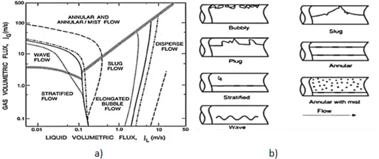
During the flow of two phases within a channel they can distribute themselves in number of ways. These distributions depend on variety of elements such as flow speed, channel geometry, direction of flow, and orientation of channel and so on. Study of two phase flow has shown that it can be categorized into number of different flow regimes.
Understanding of different flow patterns or regimes is crucial for analysis of two phase flow since the momentum, heat and mass transfer are strongly depend of the flow distribution. Hence many studies have been carried out to characterize the flow regimes of different combination of phases.
For simple case of multiphase flow within pipe (horizontal and vertical) there have been numerous literatures to investigate the dependency of the flow pattern on the mass flux, volume flux, density and viscosity and geometry. The result are usually presented in flow regime map which indicates how the flow pattern changes as one of parameter such mass flux or volumetric flux of flow changes. Figure 1 shows a typical flow map of horizontal pipe. The boundaries that have been marked in the map represent the region where the flow pattern transit to another flow pattern. This transition from one regime to another can be said to be similar to transition from laminar to turbulent in the single phase flow. However, in multiphase flow this transition can very unpredictable and depends on small and minor changes such wall shear stress. Therefore the transition that is presented in the map is not the exact transition zones.
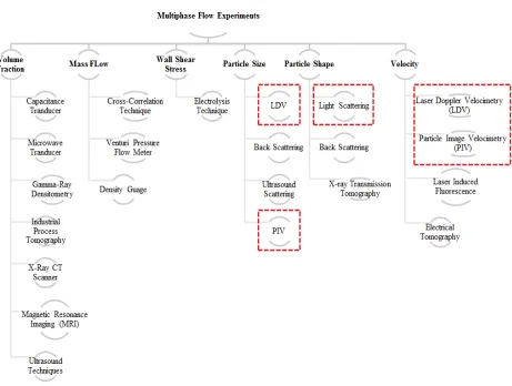
[image:3.612.121.490.318.473.2]During this literature survey some of most common and up to date measurement techniques in field of multiphase flow have been gathered. These are presented in Figure 2. There are numbers of experiments that have been proven to be successfully in measuring certain characteristics of multiphase flow. Some of experiments are only suitable for
1353, Page 3
specific phase for instance hot film probe works well when interacting with liquid and some experimental techniques have been proven to work between certain ranges of void fractions. Thus, one has to consider precisely what is needed for example what type and phases of multiphase flow will be expected during the experiments
Following the literature survey of multiphase flow measurement techniques, three measurement techniques were chosen as suitable for measurement of multiphase flow characteristics at suction of twin screw compressor. For initial experiment Light Scattering or Mie-Scattering technique will be used to observe the flow behaviour then LDV or PIV will be used to measure flow parameters in more details (3-D velocity measurement).
• Mie-scattering is one of the most frequently used techniques for visualization of flow development. It is used in the many industries for instance fuel injection in IC engines, crash test as well as visualization of multiphase flow development. This technique gives excellent information about what regime of multiphase flow is presented and transition between one to another regime(Bowers and Hrnjak 2008).
[image:4.612.73.534.125.473.2]• PIV and LDV are nonintrusive measurement techniques which allow measurement of single and multiphase flow velocities. In order to be able to use this technique flow needs to be seeded with small particles (a few microns in diameter) that allow light to be scattered and captured by the CCD camera. The tracers that can be used to determine the fluid velocity can be solid particles or liquid droplet. It is very important to select right size of tracer particles that they do not cause obstruction to the flow filed and large enough so that the light can be reflect from them. LDV techniques are well develop and it is used in varies applications. Yeh and Cummin in 1964 reported the first use of this technique. It has some similarities with PIV techniques. The only difference is that in LDV measurements the reflected beam of lights is captured
1353, Page 4
by photo detectors. LDV is single point technique meaning it measures velocity at single point whereas PIV can measure velocity of whole plane created by the beam of Laser. The CCD camera used in PIV are capable of taking tens of thousands frames per second for this reason flash lamps are not used (due to flickering effects), instead the lasers are used since they are capable of supplying short pulses and high power light beams. Simultaneous velocity measurement of each phase of gas-liquid phase of multiphase flow technique has been to be shown to be possible(Vassallo & Kumar 1999). Backward and forward scatter LDV with amplitude discrimination has been used to achieve this. LDV measurement has also been used to measure the velocities in a screw compressor (Nouri et al. 2006).
2. CFD ANALYSIS
The screw compressor used for modelling and testing in this research is oil free compressor with L/D ratio of 1.6 and 93 mm centre distance. The main rotor has 3 lobes, 127.45 mm outer diameter and wrap angle of 285º. The gate rotor has 5 lobes, outer diameter 120.38. Rotors have rack generated N profile.
SCORG (Screw COmpressor Rotor Geometry Grid generator), is the grid generator software used to generate numerical grid for screw compressors, and ANSYS CFX solver is used for calculations, (A. Kovacevic, N. Stosic 2000). SCORG uses an analytical transfinite interpolation method with adaptive meshing in order to generate full structured 3-D numerical mesh of the geometry, which can be transferred to finite volume solver. There are difficult problems which is associated with moving grid for instance stretching sliding the domain that had to be solved for robust calculations and accommodating the wide range of geometries. SCORG is integrated into DISCO (Design Integration for Screw COmpressors) software together with SCORPATH (Screw compressors profiling and thermodynamics)
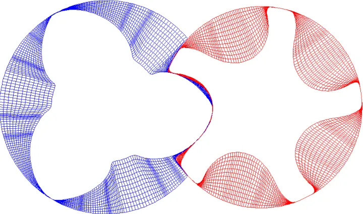
2.1 Grid Generation
[image:5.612.120.480.456.668.2]Numerical grid for the twin screw compressor was generated using SCORG is shown in Figure 3. The presented figure just shows one slice of the rotor. The grid has 65, 12, 49, circumferential, radial and angular division between each inter loop. The numerical grid then is imported into ANSYS CFX and CFX-JunctionBoxRoutines are used to read the grid as user define coordinate into the solver.
1353, Page 5
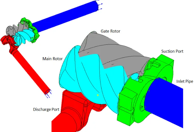
2.2 Single Phase Flow Case Setup
The grid geometry used for CFD modelling of the test compressor has been shown in Figure 4. The model consists of the circular pipe attached to the suction port, main, gate rotors and discharge port. Rotor flow domains were meshed using the SCORG while the stationary parts were meshed using ANSYS mesh generator. The working fluid is air with ideal gas properties. The suction conditions are 1.0 bar and 300 K while the discharge pressure is 2.0 bar. Convergence criteria targeted was reducing residuals by three orders of magnitude. The solver was allowed to run until satisfactory cyclic repetitions of flow were achieved across all monitored points at boundaries. SST K-Omega was chosen as turbulence model. Total mesh count for this case setup was just below 2.1 million.
2.2 Multiphase Case Setup
After solution for the whole domain was obtained, the multiphase model of the suction port was established. In the multiphase model case water was injected via a 3 mm diameter nozzle in one meter long pipe at the suction to the pipe. In order to save computational time for calculation of the multiphase flow, boundary conditions from the single
[image:6.612.136.477.192.422.2]phase calculations are extracted and applied as the boundary condition to the multiphase flow case setup.
[image:6.612.163.473.512.663.2]Figure 5 Compressor suction port setup for multiphase flow
1353, Page 6
Temperature, Velocity (x,y,z), Turbulence Eddy dissipation and Turbulence Kinetic Energy where the four parameters which were extracted from the single phase flow simulation and were applied to the outlet in the simplified geometry model.
The working fluids were air and water at 298 K. Air was the continuous phase and water was dispersed phase with droplet diameter of 30 µm. The injected water had velocity of 20 m/s. The Eulerian-Eulerian multiphase flow model was used for solving the flow in this case. The SST K-Omega was selected as turbulence model and Schiller Naumann was used for calculation of drag force. Time step size was set to match the single phase calculation because of the synchronized boundary condition.
3. RESULTS AND DISCUSSION
2.1 Single Phase
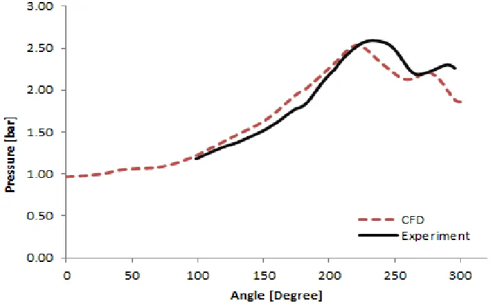
The CFD and experimental pressure rise curve up as function of angle of rotation of the male rotor is presented in Figure 6. The pressure within compressor rises to 2.5 bar which is higher than the discharge pressure which indicates over compression. The experimental pressure curve presented here was obtained by means of three pressure transducers embeded into the casing of the compressor.
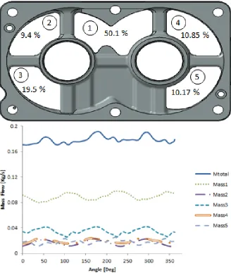
[image:7.612.123.481.273.496.2]The mass flow rate through individual parts of the suction port was calculated from the CFD. The compressor suction port was designed in way that there are five parts of the port which all connect to the rotor domains through which air can enter the compressor lobes. The majority of air flows through the middle port of the largest area. CFD result showed just over the 50 % of the flow going through this middle part of the port marked as 1. The individual mass flows through other parts of the port, namely 2, 4, and 5 are very similar to each other. The mass flow through the part of the port marked with 3 was nearly twice as much as the aggregate mass flow through positions 2, 4 and 5. The pressure at position 3 is lower than for example that at position 5 which in turn justifies the difference in flow rates. The higher mass flow through position 3 could be due to fact that Main rotor has larger suction volume compared to Gate rotor.
1353, Page 7
[image:8.612.140.468.87.475.2]For definition of boundaries in the simplified model a number of boundary conditions were tried, for example pressure, mass flow rate, velocity etc. However it was found that the velocity boundary condition gives the most accurate and repeatable boundary conditions in terms of spatial and temporal profile functions. The simplified model was first calculated for a single phase to check the results against the full case. The figures below illustrate vector plot of velocity for the two cases. It is evident that most features of velocity at suction have been captured. Thus, this simplified model can be used to model the multiphase flow at suction of screw compressor there by avoiding the presence of deforming rotor grids in the multiphase calculations. Since the pressure at suction port of screw compressor is below atmospheric pressure the air density is lower and in order to get the exact mass flow rate through the suction port the air density in this simplified model was set as constant value. The value was obtained as the average density of air at suction port for one revolution of Main rotor from the full single phase model.
1353, Page 8
Figure 8 Velocity vector plot at the suction a) Full case b) Simplified model
2.2 Multiphase Flow
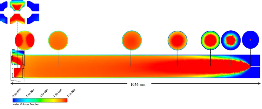
Volume fraction of water inside the suction port and the pipe is shown in the Figure 9. The volume fraction of water shown in the plot below is about 0.001 which means 0.999 of volume is occupied by air. Although this amount of water by volume might seems insignificant, it translates to just above 40 % of the mass flow due to high density. It was evident from the CFD simulation that there was no slip between the two phases and both air and water flow mixture can be assumed as homogenous flow. This could be due to the fact that the droplet diameter set for this model was just 30 µm. It was observed that the flow is fully developed by the time it reaches the midsection of the pipe. There was marginal change in water volume fraction beyond this point which means shorter pipe could have been used to achieve fully developed flow.
Figure 9 Volume fractions of water across the pipe and suction port
Water accumulation on the suction port is shown in Figure 10b. It can be seen that the water accumulates at the bottom part of the suction port. The water volume fraction in that location is above 50 %. It was found that the longer the simulation was allowed to run (more time step) the percentage of water volume fraction on surface of suction port increased further. It could have eventually reached volume fraction of 1 if the simulation was run for long enough time. This represents accumulation of liquid water in this region of the port.
Majority of water droplets flow through the middle of the window and there are no traces of water phase in the top right and left windows which is the consequence of water density. Small amount of water will enter compressor rotor from the bottom left window of the main rotor due to the higher velocity. Some of the water entering the bottom left window is the water accumulated at bottom of the suction port.
[image:9.612.85.507.400.576.2]1353, Page 9
Figure 10 a) Mixture velocities through suction port b) Water depositions on the surface of the suction port
The homogenous mixture velocity of air and water as enters the suction port has been shown in Figure 10a. Point 2 it is located at centre of the pipe and point 1 and point 3 are 35 mm either side of the midpoint. The velocity of mixture at point 1 is more than doubled as it enters the suction port. The sudden deceleration of mixture velocity as it comes to contact with bottom part of suction port can be seen from point 3. Mixture velocity at point 2 shows slight increase as it reaches the suction port.
4. EXPERIMENTAL SETUP
The test rig schematic setup for planned multiphase measurements has been presented here. Mie-Scattering technique will be used to visualize multiphase flow at suction of screw compressor. In order to visualize flow a transparent window and 1 m long transparent pipe have been installed at the suction of screw compressor. A beam of high frequency continuous light (or laser) will be used to illuminate the liquid droplet and high speed camera will be used to capture series of images.
[image:10.612.110.518.429.704.2]1353, Page 10
5. CONCLUSIONS
CFD modelling of multiphase flow at suction of screw compressor by means of simplified model has been discussed. This simplified model reduced the computational time for multiphase flow case by a factor of 10. The results of liquid injection predicted water accumulation at bottom of the suction port and showed liquid and gas phase flowing at the same velocity in the upstream pipe. It was also found that most of the injected water will flow through the middle part of the screw compressor suction port.
The future plan is to create a map of multiphase flow regime at suction port of twin screw compressor as described in the section 2 of this paper using experimental techniques and study the influence of amount and spread of the liquid phase on the performance of the compressor. Moreover, full scale simulation of multiphase in screw compressor currently is in progress, the result from this case once finished can be used to compare if the simplified model is adequate for simulating two phase flow at the screw compressor suction.
REFERENCES
A. Kovacevic, N. Stosic, I.K.S., 2000. Grid Aspects of Screw Compressor Flow Calculations. Proceedings of the ASME Advanced Energy Systems Division, 40, p.83.
Bowers, C.D. & Hrnjak, P.S., 2008. Developing Two-Phase R134a Flow after an Expansion Valve in an 8.7 mm Tube.
Brennen, C., 2005. Fundamentals of multiphase flow,
Butterworth, D.H., G.F., 1977. Two-phase flow and heat transfer,
Cao, F. et al., 2011. Experimental analysis of pressure distribution in a twin screw compressor for multiphase duties. Experimental Thermal and Fluid Science, 35(1), pp.219–225. Available at:
http://linkinghub.elsevier.com/retrieve/pii/S0894177710001858 [Accessed January 26, 2014].
J Sauls, S Branch, Trane, U., 2009. CFD analysis of refrigeration screw compressors. International Conference on Compressor and their System.
Kovacevic, A., Stosic, N. & Smith, I.K., 2002. CFD analysis of screw compressor performance. Advances of CFD in Fluid Machinery Design, Professional Engineering Publishing of ImechE, London.
M Pascu, M Heiyanthuduwage, S Mounoury, G.C. & Howden Compressors Ltd, U., 2013. Influence of the suction arrangement and geometry of the inlet port on the performance of twin screw compressors.pdf. 8th International Conference on Compressor and their System.
N. Stosic, A.K. and I.K.S., 2000. The CFD Analysis of a Screw Compressor Suction Flow. International Compressor Engineering Conference, p.Paper 1479.
N. Stosic, A. Kovacevic, Hanjalic, K. & Milutinovic, L., 1988. Mathematical Modelling of the Oil Influence Upon the Working Cycle of Screw Compressors.
Nouri, J.M. et al., 2006. Cycle-resolved velocity measurements within a screw compressor.