Simulation-based Validation of Smart Grids –
Status Quo and Future Research Trends
C. Steinbrink1, S. Lehnhoff1, S. Rohjans2, T. I. Strasser3, E. Widl3, C. Moyo3, G. Lauss3, F. Lehfuss3, M. Faschang3, P. Palensky4, A. A. van der Meer4, K. Heussen5, O. Gehrke5, E. Guillo-Sansano6, M. H. Syed6, A. Emhemed6, R. Brandl7, V. H. Nguyen8, A. Khavari9, Q. T. Tran10, P. Kotsampopoulos11,
N. Hatziargyriou11, N. Akroud12, E. Rikos13, and M. Z. Degefa14
1 OFFIS e.V., Oldenburg, Germany 2
HAW Hamburg University of Applied Sciences, Hamburg, Germany
3
AIT Austrian Institute of Technology, Vienna, Austria
4 Delft University of Technology, Delft, The Netherlands 5
Technical University of Denmark, Lyngby, Denmark
6 University of Strathclyde, Glasgow, United Kingdom 7
Fraunhofer Inst. of Wind Energy and Energy System Technology, Kassel, Germany
8 University Grenoble Alpes, G2Elab, Grenoble, France 9
European Distributed Energy Resources Lab. (DERlab) e.V., Kassel, Germany
10
Commissariat l’nergie atomique et aux nergies alternatives, Chambery, France
11
National Technical University of Athens, Athens, Greece
12
Ormazabal Corporate Technology, Bilbao, Spain
13 Centre for Renewable Energy Sources and Saving, Athens, Greece 14
SINTEF Energy Resarch, Trondheim, Norway
Abstract. Smart grid systems are characterized by high complexity due to interactions between a traditional passive network and active power electronic components, coupled using communication links. Additionally, automation and information technology plays an important role in or-der to operate and optimize such cyber-physical energy systems with a high(er) penetration of fluctuating renewable generation and controllable loads. As a result of these developments the validation on the system level becomes much more important during the whole engineering and deployment process, today. In earlier development stages and for larger system configurations laboratory-based testing is not always an option. Due to recent developments, simulation-based approaches are now an appropriate tool to support the development, implementation, and roll-out of smart grid solutions. This paper discusses the current state of simulation-based approaches and outlines the necessary future research and development directions in the domain of power and energy systems.
Keywords: Co-simulation, Cyber-Physical Energy Systems,
1
Introduction
Due to the interactions between the traditional passive network and also of ac-tive power electronic components via dedicated communication networks, smart grids tend exhibit a high degree of complexity [10]. Sophisticated automation and information technology, corresponding control algorithms and data analyt-ics methods are also of high importance for the reliable operation and opti-mization of such cyber-physical energy systems. This is so as to cope with a high(er) penetration of fluctuating renewable generation and controllable loads. As a result of these developments the validation on the system level, i.e., the testing of the integration and interaction of the connected components and al-gorithms, becomes today much more important during the whole engineering and deployment process [27, 41]. In earlier development stages and for larger system configurations laboratory-based testing is not always an option. Simu-lation in the domain of power systems is fundamental in order to understand system behaviour under normal but also in emergency situations. It also avoids costly and time-consuming real-world laboratory testing or field trials [41]. Due to recent developments, simulation-based approaches are an important tool in the development, implementation, and roll-out of smart grid solutions [29].
This paper provides a comprehensive discussion of the current state of simu-lation-based validation approaches in the domain of power and energy systems and addresses smart grid validation needs. It identifies shortcomings in today’s practice and outlines the necessary future research and development steps.
The rest of this paper is organized as follows: Section 2 briefly outlines main challenges in the validation of smart grid systems. A comprehensive overview of simulation-based smart grid development and validation approaches is given in Section 3.2 followed by a discussion of future research needs and directions. Section 5 concludes the paper with the key findings.
2
Validation Challenges
Traditionally, the separate domains of power system and Information and Com-munication Technology (ICT)/automation have been analysed individually. In the context of the smart grid advancement, and for the first time, new require-ments now demand simultaneous coverage of both domains in a comprehensive system-level validation. As already pointed out in the introduction, simulation-based approaches play a vital role in enabling this [27, 29].
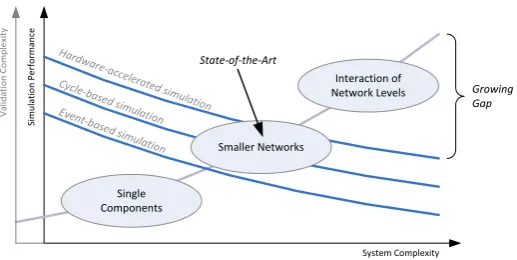
Figure 1 shows the state-of-the-art in smart grid simulation and correspond-ing validation. The system complexity grows with the extension of the analysed network part. Smart grid systems will demand modelling of the interaction of different network levels but also the integrated analysis of ICT issues.
Single Components Smaller Networks Interaction of Network Levels Si m u la ti o n P er fo rm an ce System Complexity V al id at io n C o m p le xi ty Growing Gap Hardw are-accelera ted sim ulation Cycle-b
ased simulatio n Event-b
ased simulatio n
[image:3.595.179.438.116.246.2]State-of-the-Art
Fig. 1.Growing gap between system complexity and performance of simulations
analysed at very coarse granularity. Todays tools still stem from the phase where single domains were in the focus. As soon as they get coupled with tools from other domains (ICT/automation, energy markets, customer behaviour, etc.), the performance is usually considerably reduced due to the necessary data exchange and format conversion.
In the following sections an overview of different simulation approaches is provided and future research needs and directions are derived in order to over-come the above mentioned gap.
3
Simulation-based Validation Approaches
Simulation approaches used in the power and energy domain can generally be divided into the following three areas: (i) multi-domain simulation,(ii) coop-erative simulation (also known as co-simulation), and(iii) real-time simulation and hardware-in-the-loop. An overview of all these approaches is given below.
3.1 Multi-Domain Simulation
declaration of models, strictly separating an object and interface-oriented ap-proach to “modelling” from “solving”, which is performed in a compilation step. Modelica is supported by both active open source development [11] as well as commercial packages. The third example for a purpose-built multi-domain simu-lator for smart grid algorithms is IPSYS [5, 17] and it is meant for performance-assessment of hybrid power system control strategies. Multi-domain simulators are each built on generalized principles of interaction.
Despite the powerful uses in performance assessment, system-level validation is questionable, as a multi-domain simulator typically requires the candidate sys-tem to be adapted or even reformulated to comply with the respective simulator architecture.
3.2 Co-Simulation
Overview and Distinction with other Simulation Types
Co-simulation is defined as the coordinated execution of two or more models that differ in their representation as well as in their runtime environment [37]. Representation in this context means the underlying modelling paradigm. For example, models may be represented as differential equation systems, discrete automata, etc. A runtime environment is a software system that solves model equations or generally allows the model execution. The models in a co-simulation system, therefore, have been developed as well as implemented independently. A number of simulation concepts are related to co-simulation, but differ slightly in their definitions [12]. Setups with combined development and implementation of all model systems are used for “classic” simulation. If models are developed jointly but are then separated into different runtime environments, one speaks of distributed or parallel simulation. Joint implementation and execution of models with different representation is sometimes called hybrid or merged simulation. The different types of simulation are depicted in Figure 2.
It is important to note that co-simulation implies the interaction of hardware and software components in some domains. In general, all components of a simulation setup may be either hardware or software. If hardware/software co-simulation is conducted for hardware testing, it is typically called “Hardware-in-the-Loop” (HIL) [16].
The major benefit of co-simulation is the separation of the modelling and simulation processes. Different researchers or even institutes may develop and implement simulation models representing different systems. Co-simulation users may then employ these models to analyse the dynamics of larger “systems of systems”. In other words, co-simulation supports reuse of simulation models. Ideally, these models have been created by experts of the particular domain, are properly validated, and thus acknowledged.
Generic vs. Specific Co-Simulation
Indepen-"Classic" Simulation Model
Solver Hybrid/Merged
Simulation Solver
M1 Mn
Co-Simulation S1 Sn
M1 Mn
Parallel Simulation Model
S1 Sn
Monolithic Simulation
Distributed Simulation
Monolithic Modeling Distributed
Modeling
Number of Solvers =1
>1
>1 =1
Number of Modeling Tools
[image:5.595.179.440.111.324.2]Orchestration
Fig. 2.Distinction between co-simulation and other simulation types [12, 37]
dently, the interactions of each subdomain are not yet fully understood. Many co-simulation approaches feature manual coupling of a small number of tools ad-hoc. Mainly power system and communication network simulation frameworks are regarded [20, 14, 13, 23] since they are considered the major determining fac-tors in smart grid dynamics.
Other co-simulation projects, however, support a more generic approach with a stronger inclusion of different system components. Generic co-simulation ap-proaches involve a middleware that is responsible for data exchange and tempo-ral synchronization of sevetempo-ral models. A software fulfilling these tasks is called a co-simulation framework. It typically provides a set of interfaces that may be im-plemented to establish a connection between the framework and a given model. A connected model can then indirectly exchange data with all other connected tools. The frameworks synchronization algorithm provides a common time frame for this exchange. Therefore, individual coupling between simulation tools is not necessary. This greatly reduces the likelihood of coupling errors and allows easy reuse of tools in various co-simulation studies. The difference between the man-ual ad-hoc coupling and the framework coupling is shown in Figure 3.
Model Instantiation
Simulation Software A
Simulation Software B
Co-Simulation Framework
Interface Interface
Generic Co-Simulation: Framework Coupling Simulation
Software A
Simulation Software B Interface
Specific Co-Simulation: Individual Coupling
Simulation Software C Interface
Simulation Software D Interface
Interface Interface
Interface
Simulation Software C
Simulation Software D
[image:6.595.144.432.99.316.2]Interface Interface
Fig. 3.Difference between specific and generic co-simulation [39]
might receive different inputs from a spatial resolved solar irradiation model. In other words, instantiation is used in co-simulation to account for complex inputs and boundary conditions affecting relatively simple component models. Sometimes, however, the implementation of a simulation tool does not allow for multiple instantiation of it’s models. These models are then called singletons.
Interfaces for Simulator Abstraction
words, models standardized with FMI for Co-Simulation are co-simulation-ready components while those standardized with FMI for Model Exchange are not.
All in all, it can be said that co-simulation frameworks (popular tools are Mosaik [34, 38], Ptolemy II [30], and C2WT-TE [24]) and standards are subjects to active, ongoing research. Many tools and concepts already exist with varying foci, features, and degrees of usability and popularity.
3.3 Real-time Simulation and Hardware-in-the-Loop
A simulation where a fixed time-step of the simulator, required for achieving a solution and performing I/O activities, is equal to the actual wall-clock time is commonly referred to as a real-time simulation. For validation purposes, the real-time simulation is commonly coupled with a Hardware-under-Test (HUT), adding the complexity of the hardware to the assessment procedure [16]. This advanced testing method, HIL, allows for an extensive analysis of the HUT while under a simulated broad range of operating conditions, reducing the risk associated with performing tests on an actual network and at the same time reduces the cost and time required for performing validation of power system components and energy systems.
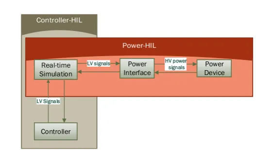
Depending on the characteristics of the HUT and the properties of interface between HUT and the real-time simulation, HIL can be classified as controller or power HIL (shown in Figure 4).
– Controller-HIL (CHIL), the HUT exchanges low voltage signals (+/-10V) with the real-time simulation. The HUT in CHIL is typically a controller device, although real-time simulations coupled to other devices such as re-lays, PMU or monitoring components are usually classified as CHIL. This devices are validated in a closed-loop environment under different dynamic and fault conditions, therefore enhancing the validation of control and pro-tection systems for power systems and energy components [40].
– Power-HIL (PHIL), the exchanged signals between simulation and HUT are of high power and therefore a dedicated power interface for amplifying the exchanged signals and injecting or absorbing power is required for coupling high power HUT with software simulation. Different approaches can be se-lected for exchanging the signals, known as interface algorithms, depending on the application and the compromise between stability and accuracy of the simulation [33]. The addition of the power interface introduces inaccu-racies into the process as the power interface cannot achieve unity gain with infinite bandwidth and zero time delay, therefore the stability and accuracy of PHIL experiments needs to be assessed before an experiment takes place. A number of compensation methods for improving the stability and the in-accuracies are frequently used within PHIL simulations [15, 42]. Hardware components without detailed simulation models are now capable of being tested through PHIL simulations.
Real-time Simulation
Power Interface
Power Device
Controller
LV signals HV power signals
[image:8.595.172.436.102.257.2]LV Signals
Fig. 4.Overview of the CHIL and PHIL simulation concepts
devices. However, sometimes the fidelity to represent the dynamics of complex power components such as power electronics converters have to be compromised due to the fixed time-step of real-time simulatons, limiting the size of the simu-lations and the transient performance [19]. For this purpose, PHIL simusimu-lations have been carried out for testing the integration of converter connected genera-tion into power systems or validating novel power converter structures [18].
4
Future Research Needs and Directions
Simulation techniques are essential in the engineering and validation of smart grid system development. As outlined above, different approaches are useful for different design stages. However, there are still several open issues related to the usage of simulations in the domain of power and energy systems. In the following, the most important research needs and target directions are discussed.
4.1 Representative Models and Model Exchange
One of the main challenges the research community faces with respect to single and multi-domain simulations is the availability of representative validated mod-els. It is crucial that the models utilized for the purpose of simulation (offline or real-time) are validated against their representative behaviour. Most domain specific simulation tools offer elementary components required in the develop-ment of complex models. These are used by the research community to develop more complex models and novel control solutions. However, the following two challenges need to be addressed:
– Intellectual Property (IP): More often than not, validated models are not shared with the wider research community due to the IP issues involved. This acts as a setback to the general progress of research.
FMI provides a potential solution to both the above challenges. FMI for Model Exchange (ME), as a standard, offers a way to develop models indepen-dent of the simulation tool, where a model is converted into a C-code, compiled, supplemented with XML-schema representing the model interactions and made available for use. As most simulation tools utilize C as their lower level language, this allows for the developed models to be imported and simulated. Furthermore, it allows for models to be exported as a black-box, protecting the IP. Although FMI-ME is well accepted within the automotive industry, at this present day, many proprietary power systems simulation tools are still yet to incorporate the FMI-ME standard. Furthermore, although the models exported from simulation tool A can be run within simulation tool B (assuming simulation tool A and B support FMI-ME), it requires both simulation tool A and B to be installed on the recipient computer, limiting the capabilities of FMI-ME.
The practice of making a software open source is widely exercised within en-ergy domains, however libraries of models are rarely open source. Open source does provide a variety of advantages that include, but are not limited to, en-couraging quality and identification of prospective collaborations.
4.2 Co-Simulation
In research, the following topics need to be addressed to meet current and up-coming requirements for co-simulation based validation of smart grid systems:
– Automated Scenario Generation/Scenario Formalization: Sets of scenarios need to be generated automatically from a relatively high-level description, if employed simulators and parameter values are known. A close-to-reality formalisation of smart grid scenarios, that can be translated into executable co-simulation scenarios (incl. validation of scenario completeness, coherence, etc.), needs to be developed.
– Simulation Interface/Description Standard:A semantic description of a sim-ulator needs to be specified. A promising interface standard is already given in form of FMI, but an additional layer providing a more direct mapping to the real world would allow automated scenario validation.
– Additional Research Domains: More research needs to be carried out in terms of integration of communication systems, economic dynamics, so-cial/psychological effects and dynamics, security-related issues, and envi-ronmental factors/dynamics into the co-simulation setup. The latter may even lead to a need of spatially resolved, GIS-based co-simulation.
to select simulators with a performance as high as possible and an output accuracy as high as necessary. Surrogate modelling should facilitate the au-tomated creation of surrogate replacements of computationally expensive simulators for performance increase.
– Data Management:Data stream management should allow for analysis, ag-gregation and monitoring of co-simulation output during the simulation pro-cess. Through big data storage, efficient long-term storage of large data sets should be enabled, allowing for data mining operations.
– Visualization:Improved tools for easy on-line monitoring and demonstration of simulation scenarios should be developed. Solutions for feeding co-simulation output into a control room/SCADA setup for the sake of training, testing or development should be realized.
– Uncertainty Quantification (UQ):The effect of the coupling of different UQ approaches handling different simulators in a co-simulation setup should be researched. Approaches for UQ should be developed, focused on uncertainty sources related with simulator interaction (e.g. different resolutions, data transformation, instable data exchange, etc). Moreover, useful aggregation and depiction of the output of UQ studies need to be developed.
4.3 Real-time Simulation and Hardware-in-the-Loop
Offering a wide range of possibilities for validation and testing of smart grid systems, current HIL technology still has several limitations. In the European project ERIGrid15, a survey was addressed at the experts in 12 top European research institutions about current limitations and mandatory future improve-ments of HIL technology (PHIL and CHIL). Current open issues can be classified into four categories:
– Limited capacity of HIL simulation for complex systems (computing power, complexity and synchronization) and for studies of non-linearity, high har-monics and transient phase.
– Limited capacity of remote HIL and geographically distributed HIL for joint experiments, mostly due to synchronization (CHIL and PHIL) and power interface stability and accuracy with respect to loop delay (PHIL).
– Difficulty in integration of HIL technology to the communication layer, par-ticularly related to the synchronization of real-time and offline simulation, as well as continuous and discrete timelines.
– Lack of a general framework to facilitate the reusability of models, infor-mation exchange among different proprietary interfaces or among different partners of a joint HIL experiment.
Due to the aforementioned issues, HIL technology needs several aspects to be improved. Overall, the following research trends can be observed and need to be addressed:
15
– Integration of Co-simulation and HIL: It is expected that integrating HIL technology into co-simulation frameworks is an important contribution to-ward a holistic approach for experimenting with cyber-physical energy sys-tems. Combining the strengths of both approaches, multi-domain experi-ments can be studied with realistic behaviours from hardware equipment under a variety of complex environments, co-simulated by appropriate and adapted simulators from the relevant domains. It will enable a complete consideration of the electrical grid to be interconnected with other domain. Until now, this is still limited. Most of the current work involving integra-tion of HIL and co-simulaintegra-tion uses only a direct coupling with the real-time simulator [4] or a CHIL setup [36].
– Remote and Geographically Distributed HIL:Latency strongly influences the accuracy (HIL) and the stability (PHIL) of a HIL test. Moreover, random packet loss due to network congestion outside of LAN may alter the in-formation and cause malfunction at the real-time simulator, including any connected hardware [31]. Up-to-now scientists have investigated the possi-bility of extending PHIL beyond laboratory geographical boundaries, and mostly, for latency tolerant applications (e.g., monitoring) [22, 28]. These developments could be a first step in enabling the possibility of remote HIL and geograhically distributed HIL.
– Interoperability and Standardization: Within a HIL-co-simulation test it is crucial to ensure seamless communication among the individual components and simulators. Additionally, when the experiments involve multiple domains or multi-laboratories, it is required to have strong interoperability between different partners [25]. A common information model is necessary to enable seamless and meaningful communication among applications. First attempts have been made towards creating a common reference model to improve in-teroperability and reusability of HIL experiments [2]. With these efforts to-wards harmonization and standardization of HIL technology, a standardized and general framework for HIL experiments can be established.
– Power Interface Stability and Accuracy: Basically, the challenge here is to synchronize and compensate the loop delay, in order to stabilize the sys-tem and increase the accuracy of a test. The first step should be selection of appropriate interface algorithms and power amplification. Recommenda-tions from [16] should be used. Secondly, a time delay compensation method could be considered, such as introducing phase shifting, low-pass filter to the feedback signal [18], extrapolation prediction to compensate for time delays [32], phase advance calibration[35] or multi-rate real-time simulation [42].
5
Conclusions
to manage, analyse and understand this novel smart grid system, simulation approaches have to be adopted.
As outlined in the paper mainly three different simulation approaches – multi-domain, co-simulation, and real-time hardware-in-the-loop – are suitable tools for analysis and validating smart grids during various development steps. Despite achievements that have been made in this area, a lot issues are yet to be solved. The main research directions related to co-simulation can be summarized as usability improvements, standardized interfaces, performance optimization, data management, and visualization. In the domain of real-time simulation and HIL, future research should address PHIL interface improvements, remote HIL, standardization and coupling with co-simulation. In summary, there remains ample space for future research in simulation-based smart grid system validation.
Acknowledgments. This work is supported by the European Communitys Horizon 2020 Program (H2020/2014-2020) under project “ERIGrid” (Grant Agreement No. 654113).
References
1. Almas, M.S., Leelaruji, R., Vanfretti, L.: Over-current relay model implementation for real time simulation & Hardware-in-the-Loop (HIL) validation. In: IECON 2012 - 38thAnnual Conference of the IEEE Ind. Electron. Society. pp. 4789–4796 (2012) 2. Andr´en, F., Lehfuss, F., Jonke, P., Strasser, T., et al.: DERri Common Reference Model for Distributed Energy Resources - Modelling Scheme, Reference Implemen-tations and Validation of Results. e & i Elektrotechnik und Informationstechnik 131(8), 378–385 (2014)
3. Bastian, J., Clauß, C., Wolf, S., Schneider, P.: Master for co-simulation using FMI. In: 8th International Modelica Conference. pp. 115–120 (2011)
4. Bian, D., Kuzlu, M., Pipattanasomporn, M., Rahman, S., Wu, Y.: Real-time co-simulation platform using OPAL-RT and OPNET for analyzing smart grid perfor-mance. In: 2015 IEEE Power and Energy Society Gen. Meeting. pp. 1–5 (2015) 5. Bindner, H., Gehrke, O., Lundsager, P., Hansen, J., Cronin, T.: IPSYS - a
sim-ulation tool for performance assessment and controller development of integrated power system distributed renewable energy generated and storage. In: European Wind Energy Conference & Exhibition (EWEC). pp. 128–130 (2004)
6. Blochwitz, T., Otter, M., Arnold, M., Bausch, C., et al.: The Functional Mockup Interface for Tool independent Exchange of Simulation Models. In: 8th Interna-tional Modelica Conference. pp. 105–114 (2011)
7. Br¨uck, D., Elmqvist, H., Mattsson, S.E., Olsson, H.: Dymola for multi-engineering modeling and simulation. In: 2ndInternational Modelica Conference (2002)
8. Davis, J., Galicia, R., Goel, M., Hylands, C., Lee, E.A., et al.: Ptolemy II: Hetero-geneous concurrent modeling and design in Java. University of California, Berkeley, Tech. Rep. UCB/ERL M 99 (1999)
9. Elmqvist, H., Mattsson, S.E.: An introduction to the physical modeling language modelica. In: 9thEuropean Simulation Symposium (ESS). vol. 97, pp. 19–23 (1997) 10. Farhangi, H.: The path of the smart grid. IEEE Power and Energy Magazine 8(1),
11. Fritzson, P.: Modelica – A cyber-physical modeling language and the OpenModel-ica environment. In: 2011 7th International Wireless Communications and Mobile
Computing Conference (IWCMC),. pp. 1648–1653 (2011)
12. Geimer, M., Kr¨uger, T., Linsel, P.: Co-simulation, gekoppelte simulation oder sim-ulatorkopplung? O+P ¨Olhydraulik und Pneumatik 50(11-12), 572–576 (2006) 13. Georg, H., M¨uller, S.C., Dorsch, N., Rehtanz, C., Wietfeld, C.: INSPIRE:
In-tegrated co-simulation of power and ICT systems for real-time evaluation. In: 2013 IEEE International Conference on Smart Grid Communications (SmartGrid-Comm). pp. 576–581 (2013)
14. Godfrey, T., Mullen, S., Griffith, D.W., Golmie, N., Dugan, R.C., Rodine, C.: Mod-eling smart grid applications with co-simulation. In: 2010 IEEE International Con-ference on Smart Grid Communications (SmartGridComm). pp. 291–296 (2010) 15. Guillo Sansano, E., Roscoe, A., Jones, C., Burt, G.: A new control method for the
power interface in power hardware-in-the-loop simulation to compensate for the time delay. In: 2014 49th International Universities Power Engineering Conference
(UPEC) (2014)
16. de Jong, E., de Graaff, R., Vaessen, P., Crolla, P., Roscoe, A., Lehfuß, F., Lauss, G., Kotsampopoulos, P., Gafaro, F.: European white book on real-time power hardware-in-the-loop testing. DERlab Report (2011)
17. Kosek, A., Lnsdorf, O., Scherfke, S., Gehrke, O., Rohjans, S.: Evaluation of smart grid control strategies in co-simulation - integration of IPSYS and mosaik. In: 2014 Power Systems Computation Conference (PSCC) (2014)
18. Kotsampopoulos, P., Kleftakis, V., Messinis, G., Hatziargyriou, N.: Design, devel-opment and operation of a PHIL environment for Distributed Energy Resources. In: IECON 2012 - 38th Annual Conference of the IEEE Industrial Electronics
So-ciety. pp. 4765–4770 (2012)
19. Kotsampopoulos, P.C., Lehfuss, F., Lauss, G.F., Bletterie, B., Hatziargyriou, N.D.: The Limitations of Digital Simulation and the Advantages of PHIL Testing in Studying Distributed Generation Provision of Ancillary Services. IEEE Transac-tions on Industrial Electronics 62(9), 5502–5515 (2015)
20. Lin, H., Sambamoorthy, S., Shukla, S., Thorp, J., Mili, L.: Power system and communication network co-simulation for smart grid applications. In: 2011 IEEE PES Innovative Smart Grid Technologies (ISGT) (2011)
21. Loddick, S., Mupambireyi, U., Blair, S., Booth, C., Li, X., Roscoe, A., Daffey, K., Rn, L.J.W.: The use of real time digital simulation and hardware in the loop to de-risk novel control algorithms. In: 2011 IEEE Electric Ship Technologies Sym-posium. pp. 213–218 (2011)
22. Lundstrom, B., Chakraborty, S., Lauss, S., Brndlinger, R., Conklin, R.: Evaluation of system-integrated smart grid devices using software- and hardware-in-the-loop. In: 2016 IEEE Power Energy Society Innovative Smart Grid Technologies Confer-ence (ISGT). pp. 1–5 (2016)
23. Mets, K., Verschueren, T., Develder, C., Vandoorn, T.L., Vandevelde, L.: Inte-grated simulation of power and communication networks for smart grid applica-tions. In: 2011 IEEE 16th International Workshop on Computer Aided Modeling and Design of Communication Links and Networks (CAMAD). pp. 61–65 (2011) 24. Neema, H., Sztipanovits, J., Burns, M., Griffor, E.: C2WT-TE: A model-based
26. Noll, C., Blochwitz, T., Neidhold, T., Kehrer, C.: Implementation of modelisar functional mock-up interfaces in SimulationX. In: 8th International Modelica
Con-ference. pp. 339–343 (2011)
27. Palensky, P., van der Meer, A., Lopez, C., Joseph, A., Pan, K.: Cosimulation of intelligent power systems: Fundamentals, software architecture, numerics, and coupling. IEEE Industrial Electronics Magazine 11(1), 34–50 (2017)
28. Palmintier, B., Lundstrom, B., Chakraborty, B., Williams, T., Schneider, K., Chas-sin, K.: A Power Hardware-in-the-Loop Platform With Remote Distribution Cir-cuit Cosimulation. IEEE Transactions on Ind. Electronics 62(4), 2236–2245 (2015) 29. Podmore, R., Robinson, M.: The role of simulators for smart grid development.
Smart Grid, IEEE Transactions on 1(2) (2010)
30. Ptolemaeus, C. (ed.): System Design, Modeling, and Simulation using Ptolemy II. Ptolemy.org (2014)
31. Ren, L., Manish, M., Mayank, P., Rob, H., Anurag, S., Siddharth, S.: Geographi-cally distributed real-time digital simulations using linear prediction. International Journal of Electrical Power and Energy Systems 84, 308–317 (2017)
32. Ren, W., Sloderbeck, M., Steurer, M., Dinavahi, V., Noda, T., Filizadeh, S., Chevrefils, A., Matar, A., Iravani, R., Dufour, C., Belanger, J., Faruque, M.O., Strunz, K., Martinez, J.A.: Interfacing issues in real-time digital simulators. IEEE Transactions on Power Delivery 26(2), 1221–1230 (2011)
33. Ren, W., Steurer, M., Baldwin, T.L.: Improve the stability and the accuracy of power hardware-in-the-loop simulation by selecting appropriate interface algo-rithms. IEEE Transactions on Industry Applications 44(4), 1286–1294 (2008) 34. Rohjans, S., Lehnhoff, S., Sch¨utte, S., Scherfke, S., Hussain, S.: mosaik – A modular
platform for the evaluation of agent-based Smart Grid control. In: 4thIEEE/PES
Innovative Smart Grid Technologies Europe (ISGT EUROPE) (2013)
35. Roscoe, A.J., Mackay, A., Burt, G.M., McDonald, J.R.: Architecture of a network-in-the-loop environment for characterizing ac power-system behavior. IEEE Trans-actions on Industrial Electronics 57(4), 1245–1253 (2010)
36. Rotger-Griful, S., Chatzivasileiadis, S., Jacobsen, R.H., Stewart, E.M., Domingo, J.M., Wetter, M.: Hardware-in-the-Loop co-simulation of distribution Grid for de-mand response. In: 2016 Power Systems Comp. Conf. (PSCC). pp. 1–7 (2016) 37. Schloegl, F., Rohjans, S., Lehnhoff, S., Velasquez, J., Steinbrink, C., Palensky, P.:
Towards a Classification Scheme for Co-Simulation Approaches in Energy Sys-tems. In: International Symposium on Smart Electric Distribution Systems and Technologies (EDST), 2015. pp. 516–521 (2015)
38. Sch¨utte, S., Scherfke, S., Tr¨oschel, M.: Mosaik: A framework for modular simulation of active components in Smart Grids. In: IEEE First International Workshop on Smart Grid Modeling and Simulation (SGMS). pp. 55–60 (2011)
39. Steinbrink, C.: A Nonintrusive Uncertainty Quantification System for Modular Smart Grid Co-Simulation. Ph.D. thesis, University of Oldenburg (2016)
40. Steurer, M., Bogdan, F., Ren, W., Sloderbeck, M., Woodruff, S.: Controller and power hardware-in-loop methods for accelerating renewable energy integration. In: Power Engineering Society General Meeting, 2007. IEEE. pp. 1–4 (2007)
41. Strasser, T., Pr¨ostl Andr´en, F., Lauss, G., et al.: Towards holistic power distribu-tion system validadistribu-tion and testing—an overview and discussion of different possi-bilities. e & i Elektrotechnik und Informationstechnik 134(1), 71–77 (2017) 42. Viehweider, A., Lauss, G., Felix, L.: Stabilization of power hardware-in-the-loop
![Fig. 2. Distinction between co-simulation and other simulation types [12, 37]](https://thumb-us.123doks.com/thumbv2/123dok_us/1491286.101799/5.595.179.440.111.324/fig-distinction-simulation-simulation-types.webp)
![Fig. 3. Difference between specific and generic co-simulation [39]](https://thumb-us.123doks.com/thumbv2/123dok_us/1491286.101799/6.595.144.432.99.316/fig-dierence-specic-generic-simulation.webp)