RIT Scholar Works
Theses
Thesis/Dissertation Collections
5-2014
Abstracted Workflow Framework with a Structure
from Motion Application
Adam J. Rossi
Follow this and additional works at:
http://scholarworks.rit.edu/theses
This Thesis is brought to you for free and open access by the Thesis/Dissertation Collections at RIT Scholar Works. It has been accepted for inclusion in Theses by an authorized administrator of RIT Scholar Works. For more information, please [email protected].
Recommended Citation
with a Structure from Motion Application
by
Adam J. Rossi
A.S. Monroe Community College, 2001
B.S. Rochester Institute of Technology, 2004
A thesis submitted in partial fulfillment of the
requirements for the degree of Master of Science
in the Chester F. Carlson Center for Imaging Science
College of Science
Rochester Institute of Technology
May 2014
Signature of the Author
Accepted by
COLLEGE OF SCIENCE
ROCHESTER INSTITUTE OF TECHNOLOGY
ROCHESTER, NEW YORK
CERTIFICATE OF APPROVAL
M.S. DEGREE THESIS
The M.S. Degree Thesis of Adam J. Rossi has been examined and approved by the
thesis committee as satisfactory for the thesis required for the
M.S. degree in Imaging Science
Dr. Harvey Rhody, Thesis Advisor
Dr. Carl Salvaggio
Dr. Derek Walvoord
Date
with a Structure from Motion Application
by
Adam J. Rossi
Submitted to the
Chester F. Carlson Center for Imaging Science in partial fulfillment of the requirements
for the Master of Science Degree at the Rochester Institute of Technology
Abstract
In scientific and engineering disciplines, from academia to industry, there is an increasing need for the development of custom software to perform experiments, construct systems, and develop products. The natural mindset initially is to shortcut and bypass all overhead and process rigor in order to obtain an immediate result for the problem at hand, with the misconception that the software will simply be thrown away at the end. In a majority of the cases, it turns out the software persists for many years, and likely ends up in production systems for which it was not initially intended. In the current study, a framework that can be used in both industry and academic applications mitigates underlying problems associated with developing scientific and engineering software. This results in software that is much more maintainable, documented, and usable by others, specifically allowing new users to extend capabilities of components already implemented in the framework.
There is a multi-disciplinary need in the fields of imaging science, computer science, and software engineering for a unified implementation model, which motivates the development of an abstracted software framework. Structure from motion (SfM) has been identified as one use case where the abstracted workflow framework can improve research efficiencies and eliminate implementation redundancies in scientific fields. The SfM process begins by obtaining 2D images of a scene from different perspectives. Features from the images are extracted and correspondences are established. This provides a sufficient amount of information to initialize the problem for fully automated processing. Transformations are established between views, and 3D points are established via triangulation algorithms. The parameters for the camera models for all views / images are solved through bundle adjustment, establishing a highly consistent point cloud. The initial sparse point cloud and camera matrices are used to generate a dense point cloud through patch based techniques or densification algorithms such as Semi-Global Matching (SGM). The point cloud can be
viewer. The SfM workflow can be implemented in the abstracted framework, making it easily leverageable and extensible by multiple users.
Like many processes in scientific and engineering domains, the workflow described for SfM is complex and requires many disparate components to form a functional system, often utilizing algorithms implemented by many users in different languages / environments and without knowledge of how the component fits into the larger system. In practice, this generally leads to issues interfacing the components, building the software for desired platforms, understanding its concept of operations, and how it can be manipulated in order to fit the desired function for a particular application. In addition, other scientists and engineers instinctively wish to analyze the performance of the system, establish new algorithms, optimize existing processes, and establish new functionality based on current research. This requires a framework whereby new components can be easily plugged in without affecting the current implemented functionality.
The need for a universal programming environment establishes the motivation for the development of the abstracted workflow framework. This software implementation, named Catena, provides base classes from which new components must derive in order to operate within the framework. The derivation mandates requirements be satisfied in order to provide a complete implementation. Additionally, the developer must provide documentation of the component in terms of its overall function and inputs. The interface input and output values corresponding to the component must be defined in terms of their respective data types, and the implementation uses mechanisms within the framework to retrieve and send the values. This process requires the developer to componentize their algorithm rather than implement it monolithically. Although the requirements of the developer are slightly greater, the benefits realized from using Catena far outweigh the overhead, and results in extensible software. This thesis provides a basis for the abstracted workflow framework concept and the Catena software implementation. The benefits are also illustrated using a detailed examination of the SfM process as an example application.
I would like to thank my advisor, Dr. Harvey Rhody, for his willingness to take me on as a research student and develop a thesis topic that was well-suited for my interests and background. I was fortunate to have taken many courses with Dr. Rhody, and it was a pleasure getting to know him as my thesis advisor throughout the course of our research. His personal and professional advice have been invaluable to me. I’m always amazed at how often I discover the applicability and foresight of his abstractions in practice.
Thanks to my committee members, Dr. Carl Salvaggio and Dr. Derek Walvoord. After taking my first class with Carl, it became obvious that he is one of the exceptional teachers at RIT. He truly cares about his students and puts a great deal of effort into lectures and class material. He is student-focused and goes out of his way to make sure they succeed. Additionally, I am very grateful not only to have Derek on my committee, but to have him as a teaching assistant for many courses, and for the privilege of working with him at Exelis. Derek solidified Image Science coursework theory through application and educated me in new subject areas. I am very grateful for the opportunity to work with Derek and I greatly value our friendship.
I would like to thank all the faculty, staff, and students at the Center for Imaging Science at RIT. Although I was a part-time student and infrequently on campus, they were very welcoming and helpful. I am also appreciative of their willingness to experiment with the Catena software, and I hope they were able to gain from their investment.
I would like to give special thanks to my family and friends for their support. You kept me motivated and helped me accomplish a significant milestone in my academic career.
Also, thank you to my former co-workers at Exelis (in alphabetical order): Bernie Brower, Brad Paul, Brian Staab, Brian Terwilliger, Frank Tantalo, Jason Wynne, Jon Antal, Ken Brodeur, Kevin Pietrzak, Tim Burt, and Wendy LeFebvre. You played a key role in the development of my career. Special thanks to those who adapted the Catena framework. Your input was invaluable for increasing software quality and flexibility: Bran-don May, Jordyn Stoddard, Kyle Ausfeld, and Sue Munn. I would also like to thank my GPS III teammates. We spent a lot of time away from home supporting a crucial project that is going to improve national security: Bill Taft, Chris Bower, Greg Kirchoff, Howard Brayman, Paul Gilmour, Rich Lourette, Steph Panicali, and Tim Flynn.
Thank you to the following musicians for providing a soundtrack to writing my thesis and coding: Underworld, Com Truise, Tycho, Junior Boys, Hot Chip, Toro Y Moi, Lusine, Bibio, Cut/Copy, Gold Panda, Aphex Twin, Boards of Canada, Washed Out, Tangerine Dream, Philip Glass, and The Bad Plus.
Lastly, thank you to ITT / Exelis Geospatial Systems for the financial support of my education.
She made numerous sacrifices to ensure my success, and I am forever indebted to her. Thank you for your loving support, Jamie.
1 Introduction 1
1.1 Problem Definition . . . 1
1.2 Motivation . . . 1
1.3 Outline of Thesis . . . 3
2 Objectives 4 2.1 Structure from Motion (Image Science) . . . 4
2.2 Workflow Framework (Software Engineering) . . . 5
2.3 Benefits of the Multi-Disciplinary Abstracted Workflow Framework . . . 5
3 Implementation 6 3.1 Workflow Framework . . . 6
3.1.1 Stages . . . 6
3.1.2 Chain . . . 9
3.1.3 Rendering . . . 9
3.2 Catena . . . 10
3.2.1 Stage Implementation . . . 10
3.2.2 Chain Implementation . . . 15
3.2.3 Stage Development Patterns . . . 21
3.2.4 Tap Point Stage . . . 25
3.2.5 Unit Test . . . 25
3.2.6 Chain Builder . . . 26
3.2.7 Chain GUI . . . 26
3.2.8 Design Approaches . . . 28
3.2.9 Interface Definition Advantages . . . 31
3.2.10 Optimization Process . . . 32
3.2.11 Platform / Implementation Issues . . . 32
3.2.12 Deployment Considerations . . . 33
4 SfM Theory 34
4.1 Image Source . . . 34
4.2 Image Filtering / Subsets . . . 35
4.3 Symbolic Links . . . 36
4.4 Image Conversion . . . 36
4.5 Feature Extraction . . . 37
4.5.1 SIFT . . . 37
4.6 Feature Matching / Filtering . . . 42
4.7 Image-Based Geometry Estimation . . . 44
4.7.1 Camera Model . . . 44
4.7.2 Epipolar Geometry . . . 45
4.7.3 Fundamental Matrix . . . 46
4.7.4 Fundamental Matrix Extensions Using Projective Transforms . . . . 47
4.7.5 Fundamental Matrix From Correspondences . . . 48
4.7.6 Iterative Fundamental Matrix Computation . . . 50
4.7.7 Triangulation & Point Cloud Generation . . . 51
4.8 Radial Distortion Compensation . . . 52
4.9 Output Conversion . . . 53
4.10 View Clustering / Reduction . . . 53
4.11 Dense Point Cloud Generation . . . 55
4.12 Geographic Considerations . . . 56
4.13 Surface Reconstruction . . . 56
4.14 Visualization / Exploitation . . . 57
4.15 SfM Chain . . . 58
5 Results 60 5.1 SfM Application . . . 60
5.1.1 ET . . . 60
5.1.2 Hall . . . 63
5.1.3 RIT WASP . . . 66
5.1.4 ITT Exelis WAMI . . . 69
5.2 Extensibility . . . 72
5.2.1 Registration . . . 72
5.2.2 Health Imaging . . . 73
6 Conclusions 76
6.1 Overview . . . 76
6.2 Abstraction Benefits . . . 77
6.3 Future Development . . . 77
6.3.1 Binary Overlays . . . 77
6.3.2 Composite Stages . . . 78
6.3.3 Generalized Property Optimization . . . 78
6.3.4 Distributed / Multi-threaded Execution . . . 78
A Supporting Information 79 A.1 Cross-product Notation . . . 79
A.2 Auto-generated Stage Documentation . . . 79
Bibliography 97
Acronyms 101
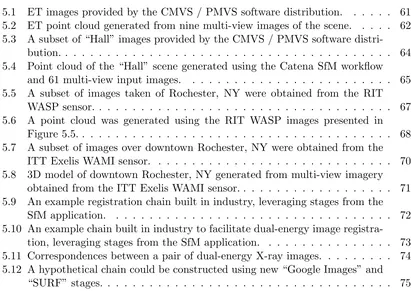
3.1 Generalized chain representation showing the connection of stages to
com-pose a workflow. . . 7
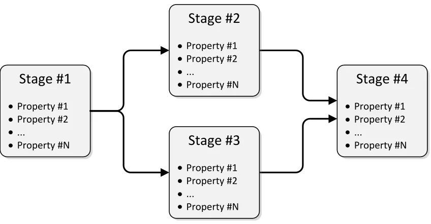
3.2 Representative stage structure showing properties and input / output
in-terfaces. The input data comes from previous stages, while the output data is fed into the subsequent stage(s). The individual stage interfaces are well-defined such that equivalent stages can be swapped for other
imple-mentations in a chain. . . 8
3.3 StageBase class diagram and two derived classes / stages. The StageBase
class is the fundamental component in the workflow framework, from which
every stage must inherit. . . 8
3.4 High-level SfM chain defining all the steps of the algorithm. . . 15
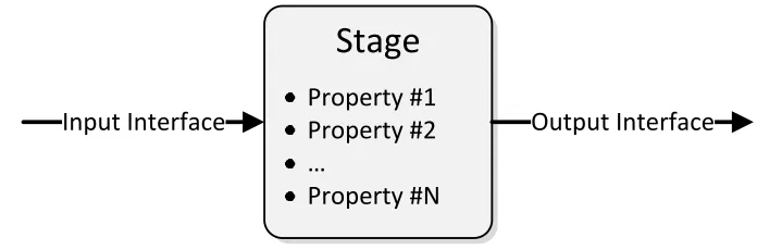
3.5 The Chain Builder GUI provides a graphical interface to construct
work-flows, browse stage packages, modify stage properties, and render chains. . . 27
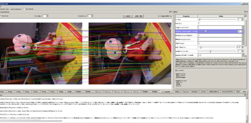
3.6 The Chain GUI accepts a programmatically constructed chain and provides
a graphical interface to modify stage properties, render chains, and most importantly, visualize the outputs of stages. This provides feedback to tune
stage parameters. . . 29
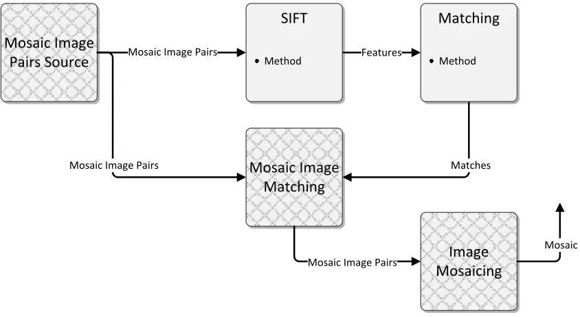
3.7 The image mosaicing chain uses feature extraction and matching stages
from the SfM application to warp images with overlap into a composite
virtual image mosaic. . . 31
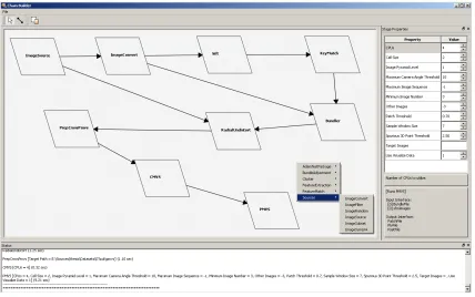
4.1 The Image Source stage generates a list of images from a given path and
extension. This is typically the first stage in a chain. . . 35
4.2 The Image Subset stage takes a list of images and down-selects using the
supplied criteria. . . 36
4.3 The Image Symbolic Link stage creates symbolic links to images on Unix
operating systems to establish a working directory. . . 36
4.4 The Image Convert stage converts images to a desired file format. . . 37
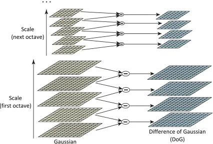
4.5 The SIFT algorithm establishes a difference of Gaussian scale space by
convolving images at each octave to yield intervals. Reproduced from [1]. . 39
4.6 The SIFT algorithm finds scale space extrema by comparing the 8-point
neighborhood at the current scale and 9-point neighborhood of adjacent
scales. Reproduced from [1]. . . 40
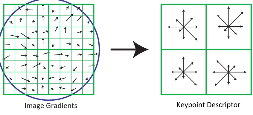
4.7 The SIFT descriptor is computed from localized gradients combined into
localized histograms of magnitudes and orientations. Reproduced from [1]. . 41
4.8 The SIFT Stage implements the SIFT algorithm, generating keypoint
de-scriptors for each of the images provided. . . 42
4.9 Keypoint descriptor class diagram illustrating the power of object-oriented
design and polymorphism to handle multiple keypoint descriptor file formats. 42 4.10 The Feature Matching stage generates a match table for every image
com-bination using the independently generated keypoint descriptors. . . 43
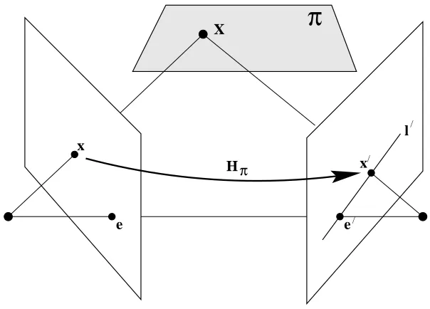
4.11 Epipolar geometry illustrations for point correspondences. Reproduced
from Hartley and Zisserman [2]. . . 46
4.12 Image coordinates can be projected using the epipolar homography: x0 =
Hπx. Reproduced from Hartley and Zisserman [2]. . . 47
4.13 The Bundler Stage performs a bundle adjustment process using keypoint matches and images in order to generate consistent camera matrices, sparse
point cloud, and 2D to 3D point correspondences. . . 50
4.14 Triangulation methods are used to solve for the 3D point (Xˆ) given the 2D
image correspondence coordinates (x and x0). The triangulation error is
highlighted in the figure as d and d0, which is the difference in the
corre-spondence points from the projection of Xˆ (ˆx and ˆx0). Reproduced from
Hartley and Zisserman [2]. . . 51
4.15 The Radial Undistort stage compensates for radial distortion detected in
the images to improve down-stream processes. . . 52
4.16 The Prep CMVS / PMVS stage converts the Bundler output to an
accept-able form for CMVS and PMVS. . . 53
4.17 The CMVS stage detects and filters redundant views in preparation for
PMVS. . . 55
4.18 The PMVS stage uses the consistent camera matrices found by Bundler to
generate a dense point cloud using a patch-based technique. . . 56
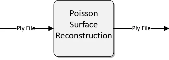
4.19 The Poisson Surface Reconstruction stage performs interpolation of vertices
to generate faces between 3D points, yielding a meshed 3D model. . . 57
4.20 The MeshLab stage provides visualization of the 3D point cloud and model. 58 4.21 The complete SfM chain used to generate 3D models from multi-view 2D
5.1 ET images provided by the CMVS / PMVS software distribution. . . 61
5.2 ET point cloud generated from nine multi-view images of the scene. . . 62
5.3 A subset of “Hall” images provided by the CMVS / PMVS software
distri-bution. . . 64
5.4 Point cloud of the “Hall” scene generated using the Catena SfM workflow
and 61 multi-view input images. . . 65
5.5 A subset of images taken of Rochester, NY were obtained from the RIT
WASP sensor. . . 67
[image:13.612.140.551.169.460.2]5.6 A point cloud was generated using the RIT WASP images presented in
Figure 5.5. . . 68
5.7 A subset of images over downtown Rochester, NY were obtained from the
ITT Exelis WAMI sensor. . . 70
5.8 3D model of downtown Rochester, NY generated from multi-view imagery
obtained from the ITT Exelis WAMI sensor. . . 71
5.9 An example registration chain built in industry, leveraging stages from the
SfM application. . . 72
5.10 An example chain built in industry to facilitate dual-energy image
registra-tion, leveraging stages from the SfM application. . . 73
5.11 Correspondences between a pair of dual-energy X-ray images. . . 74
5.12 A hypothetical chain could be constructed using new “Google Images” and
1 The code provides an example of a complete implementation of a stage that
outputs resolution information of given images to a file. . . 11
2 A script that programmatically builds a SfM Catena chain. . . 16
3 A script that loads a persisted Catena chain and renders the tail stage. . . . 20
4 Example of theShouldRunutility method for executing external applications. 21
5 An example of the RunCommand method provided on the StageBase class,
which is used to invoke external applications. . . 22
6 An example class derived from theCommon.ImageProcessStageBaseclass.
The base class provides common stage functionality for stages that define
sfmImage(s)on both their input and output interface. . . 24
7 An example Catena chain that uses theTapPointstage to inspect
interme-diate stage output values. . . 25
8 SfM chain used as an example for the Chain GUI. . . 26
9 Example invocation of the Chain GUI visualization tool. . . 27
10 The data structure required for stage visualizations using the Chain GUI. . 27
11 The data structure required for stage property sheets using the Chain GUI. 28
12 The data structure required for stage property ranges using the Chain GUI. 28
Introduction
1.1
Problem Definition
In many scientific communities, including imaging science, it is common for a process to be defined, which requires various algorithms and tools in order to carry out a specific task. It is typically advantageous for the scientist to leverage previous work developed by others in order to advance a particular aspect of the field. This ultimately involves combining components implemented by others in order to establish a baseline system for the scientist’s research and development. However, it is likely that the components were not developed together nor envisioned as being part of a greater overarching system, and they are likely inflexible for accomplishing a different goal. There is usually little to no consideration given to reuse or documentation, especially in the context of developing prototype software. This effectively results in monolithic, platform-specific, and disposable software that has limited use in specialized domains by a small group of users. This problem becomes amplified when multiple tools, developed by multiple users, are required to carry out a task. Since tools are developed without considering the overall scope, they are difficult to integrate. The need for a workflow framework that integrates applications and allows for flexible extensions and replacement components becomes apparent.
1.2
Motivation
The structure from motion (SfM) task requires the integration of many proprietary and open-source components in order to effectively carry out the processing. The common steps are enumerated below:
1. Image source specification
2. Image list filtering / creating subsets
3. Creating symbolic links
4. Image conversion
5. Feature extraction
6. Feature matching
7. Bundle adjustment
8. Radial distortion compensation
9. Output conversion
10. View reduction
11. Point cloud generation
12. Surface reconstruction / image draping
13. Visualization / exploitation
Historically, components for the SfM process have been implemented in various lan-guages, had inconsistent interfaces, required various input data formats, and were generally incompatible with each other. If one wishes to establish a working SfM system, there is a steep learning curve and a considerable amount of time required to establish a base sys-tem. The integration of the components is typically very application and platform-specific, making it difficult for others to leverage previous work. Additionally, this solution does not result in a robust processing system and makes it difficult for users to utilize it as a test bed for the development of alternative algorithms and components. Therefore, an abstract solution to this problem will be presented, which can be utilized for the SfM process, and more generally applied to other domains.
In general, there are varying levels of operating environments for SfM, or any scientific application:
2. Semi-Automated Method: This provides a static workflow definition that cannot be changed to accommodate new components or utilized for alternative applications. Much of the implementation is “hard-coded” or otherwise inflexible.
3. Fully Automated Method: A flexible, automated workflow framework integrates disparate tools for general applications. The interface between components is ad-dressed to provide inter-operability of different component implementations through strong contract. The components and workflow are self-documenting to promote reuse by other users.
Typically, the semi-automated method is used to conduct research in the SfM domain. Previous approaches, including scripts, Open Street Map (OSM) [3], and Visual SfM [4] have allowed for automation of the workflow; however, these are static definitions that lack extensibility and applicability to other domains. Therefore, the ideal solution for scientists is a flexible workflow framework, which is not only needed by the SfM community, but for scientific and engineering fields in general. By creating an abstract solution to this problem, the fundamental components become applicable to other domains and the com-ponents can be reused within the same general workflow specification. This thesis describes the development of the abstracted workflow framework, Catena, and its applicability to improving/optimizing the environment for scientific research in the SfM field.
1.3
Outline of Thesis
This thesis is organized in the following manner:
• Chapter 2: The thesis research is motivated by establishing an objective that addresses a common need for an abstracted workflow framework in many scientific and engineering domains.
• Chapter 3: Implementation and design details of the abstracted workflow frame-work and the Catena software implementation are presented.
• Chapter 4: The image science theory of the SfM application is presented, and implementation of the SfM components in the Catena framework is described.
• Chapter 5: Using the SfM workflow, 3D models from multi-view imagery were generated. Components from the SfM workflow were leveraged for other applications to demonstrate the extensibility of Catena.
Objectives
In many applications, the manual or semi-automated solution to a scientific problem is used, but lacks the flexibility and extensibility for use in future implementations. Using the SfM implementation as an example, it is clear that monolithic software development yields disposable software, which cannot be leveraged by future researchers. The solution to this issue is multi-disciplinary, drawing on imaging science theory and software engineering architecture, design, and implementation. Often there is disparity between these two disciplines; image scientists tend to minimize the software component because they analyze the problem in its native, entire form, while software engineers lack the theory knowledge to allow for componentization and algorithm substitution. Analysis of the independent requirements (i.e., without consideration for the other field) are described in Section 2.1 from an image scientist’s perspective and Section 2.2 from a software engineer’s perspective as it relates to the SfM implementation. Ultimately, a fully automated solution is required, which draws on strengths from both complementary fields of study to leverage design and implementation of an abstracted workflow framework. The benefits of the abstracted workflow framework will be exemplified in the SfM application.
2.1
Structure from Motion (Image Science)
Currently, the SfM implementation is run manually or semi-automatically with disparate components, which tends to be error-prone and time-consuming. Therefore, the need exists for a tool that easily integrates these individual components for fully automated execution of the process. Ideally, the resulting framework would provide a method of implementation that is extensible, and which minimizes the overhead to the researcher. A constrained environment for research and development would allow for consistency between users, and allow them to express the workflow in terms of components. This fully automated
solution must inherently allow for optimization of algorithms, and provide a method for documentation of algorithms, parameters, and interfaces.
2.2
Workflow Framework (Software Engineering)
The software engineering approach to the SfM application includes componentization with defined interfaces and documentation according to a contract set forth by the framework, such that the framework automatically executes the necessary steps that enable the com-ponents to be reused. High-level implementation in a cross-platform language would be required such that the framework may be run on any operating system with little-to-no consideration to maintain platform independence. The framework must be executed ef-ficiently, requiring minimal computational resources, and allowing for parallel execution using all available cores and compute nodes without additional burden on the developer (i.e., feature of the framework). The framework should be able to persist / restore its state, and provide programmatic and graphical interfaces. Component interfaces should be defined / specified, and as such, the framework would validate legal combinations of constructed components.
2.3
Benefits of the Multi-Disciplinary Abstracted Workflow
Framework
Implementation
3.1
Workflow Framework
In many domains, the concept of a workflow, orchain, is applied to carry out a sequence
of tasks that can be represented by individual stages. This concept is often utilized in
the area of image processing. The output from a given stage is fed into subsequent stages and becomes the input required to carry out a specific process. The generalization of this concept is shown in Figure 3.1. This process continues sequentially until the final stage is complete. In the current study, the abstracted workflow framework, named Catena [5], was implemented in the Python programming language due to its object-oriented, platform-agnostic, and ubiquitous nature. In addition, Python has gained a large following through-out the scientific community and most of the anticipated target users are familiar with this language. Chains can be built programmatically or through the usage of a graphical user interface (GUI). Both methods support persistence for interoperability between en-vironments and future usage of the constructed chain. The stages included as part of the core framework, and custom stages implemented by users, are dynamically discovered and loaded for ease of deployment, integration, operation, and extensibility.
3.1.1 Stages
The fundamental component of the workflow is the stage. The stage encapsulates a func-tion and should be developed in such a manner that provides general capability across chain instances (i.e., it should be designed generically so that it can be leveraged by other applications). A stage defines three classes of information within it: the properties and self-documentation; input interface; and output interface (Figure 3.2). The properties required in the class constructor are used to control behavior and modes of the stage.
Stage #1
Property #1 Property #2 ...
Property #N
Stage #2
Property #1 Property #2 ...
Property #N
Stage #3
Property #1 Property #2 ...
Property #N
Stage #4
Property #1 Property #2 ...
[image:21.612.128.552.127.348.2]Property #N
Figure 3.1: Generalized chain representation showing the connection of stages to compose a workflow.
ditionally, information contained in the constructor facilitates self-documentation of the stage, whereby it can be utilized to provide online help for users. Next, the input interface is declared with type information. This is required prior to rendering the chain to validate interface consistency among connected stages. Finally, the output interface is defined in the same manner as the input. The advantage of defining stage interfaces is that it allows the user to conveniently exchange one stage for another.
Stage
Input Interface
Property #1
Property #2
Output Interface
…
[image:22.612.160.508.127.242.2]Property #N
Figure 3.2: Representative stage structure showing properties and input / output inter-faces. The input data comes from previous stages, while the output data is fed into the subsequent stage(s). The individual stage interfaces are well-defined such that equivalent stages can be swapped for other implementations in a chain.
+AddInputStage() +AddOutputStage() +RemoveConnections() +GetInputStages() +GetOutputStages() +NumInputStages() +GetPropertyMap() +GetPackageName() +GetStageName() +GetStageDescription() +GetPropertyDescription() +SetPropertyDescription() +GetProperty() +SetProperty() +GetInputStagesInterfaces() +Reset() +Prepare() +InitializeOutputCache() +ValidateCompleteOutputCache() +GetOuput() +GetOutputByKey() +GetInputStageValue() +SetOutputValue() +StartProcess() +RunCommand() +GetInputInterface() +GetOutputInterface() +Execute() StageBase -stageDoc -parameterDoc -properties -inputStages -outputStages -outputCache -prepared -uid +GetInputInterface() +GetOutputInterface() +WriteBundlerOptionsFile() +Execute() Bundler +GetInputInterface() +GetOutputInterface() +Process() +Execute() Sift
[image:22.612.220.463.332.581.2]3.1.2 Chain
A chain is composed of an arbitrarily complex sequence of stages representing a desired workflow that is required to carry out a task. The user has the ability to employ a stage as input into one or many down-stream stages, or even include it in different chain segments. In addition, the user may construct the chain in such a manner that results in more than one output stage. In this case, the output stages and the respective chains can be rendered in parallel or sequentially.
3.1.3 Rendering
Once a chain is constructed from a collection of stages, it is ready for rendering. The verb render is borrowed from the image processing concept, describing the method by which the chain is executed to produce the desired output. The chain is rendered in a
demand-pull fashion. This means that the chain is rendered from the perspective of the output stage. The request is made from stage to stage up-stream, and each stage executes its function in order to produce an output for the stage(s) in front of it.
In addition, caching is employed as the chain is rendered so that a stage and its asso-ciated outputs are only calculated once. This is essential in minimizing the computation time of the overall chain. The caching scheme described is beneficial when a chain is constructed with one stage connected to multiple up- or down-stream stages. It is impor-tant to note that the developer is isolated from the rendering and caching details, as the development methodology described in Section 3.1.1 ensures that both are employed as part of the framework.
3.2
Catena
Catena [5] is an abstracted workflow framework implemented in the Python programming language that allows for the development of stages and chains. The stage and chain prop-erties are defined at a high level and subsequently demonstrated with the SfM application. This fully automated method was originally designed to solve SfM problems, however ben-efits of the abstracted workflow framework have been realized in other scientific domains and will be discussed. Catena ensures that stage implementation is intuitive, stage con-nectivity is consistent in the development of chains, and re-use is promoted throughout many fields of study.
3.2.1 Stage Implementation
import Chain
import Common
class ResolutionInfo(Chain.StageBase):
def __init__(self, inputStages=None, resolutionFilePath=""):
Chain.StageBase.__init__(self,
inputStages,
"Resolution Information", {"Resolution Path":
"Path to resolution information file"})
self._properties["Resolution Path"] = resolutionFilePath
def GetInputInterface(self):
return {"images":(0,Common.sfmImages)}
def GetOutputInterface(self):
return {"images":Common.sfmImages}
def Execute(self):
images = self.GetInputStageValue(0, "images")
self.StartProcess()
f = open(self._properties["Resolution Path"], "w")
for im in images.GetImages():
f.write("%s: xres=%d, yres=%d\n" % (im.GetFileName(), im.GetXResolution(), im.GetYResolution())) f.close()
self.SetOutputValue("images", images)
Listing 1: The code provides an example of a complete implementation of a stage that outputs resolution information of given images to a file.
Module Imports
First, theChainandCommonmodules are imported. TheChainmodule contains the base
Catena functionality and theStageBaseclass, from which all Catena stages must inherit.
import Chain
import Common
Class Definition
Next, the class is defined. As previously mentioned, all Catena stages must inherit from
Chain.StageBase. This base class contains the fundamental power and stage functional-ity.
class ResolutionInfo(Chain.StageBase):
Constructor
The convention in Catena is for the constructor to take a list of input stages as the first parameter. The subsequent parameters are optional and specific to the stage being implemented. Another requirement is that each parameter be given a default value. This serves a dual purpose as it provides a nominal parameter setting in the event the user does not wish to override the default value, and the default parameter value conveys important data type information to the framework (as Python is a loosely typed language).
def __init__(self, inputStages=None, resolutionFilePath=""):
Constructor Implementation
The base class’ constructor must be called immediately. The constructor takes three
parameters, including a list of input stages, a string that describes the stage, and a dic-tionary. Each item of the dictionary describes the parameters of the stage. The key is the parameter name, and the value is a description of the parameter. This information serves as self-documentation in other applications, such as the Chain Builder and Chain GUI, that offers users online help.
Chain.StageBase.__init__(self,
inputStages,
"Resolution Information", {"Resolution Path":
Stage Properties
Lastly, the properties dictionary is initialized using the parameters of the stage, provided as parameters to the constructor. At this point, the user is free to carry out other initial-ization procedures required for the stage.
self._properties["Resolution Path"] = resolutionFilePath
Input Interface
TheGetInputInterfacemethod must be implemented (overloaded) as part of theStageBase
contract. This is effectively a “pure virtual” method. A dictionary must be returned, which represents the input interface. The item’s key is the input parameter name and the value is a 2-tuple, where the first value is the index of the input stage from which the parameter originates. The second value is the type of the parameter. This information is used to perform interface consistency as chains are constructed, and to enforce type compatibility. This allows the framework to perform run-time checking to minimize user errors both in development and application.
def GetInputInterface(self):
return {"images":(0,Common.sfmImages)}
Output Interface
The GetOutputInterface method is similar to the input method in that it defines the
output parameters produced by the stage. The only difference is that the value of the dictionary items is not a tuple, it is simply the data type of the output parameter.
def GetOutputInterface(self):
Execution Method
The final method required by the framework is the Execute method. This is where the
core functionality of the stage is carried out.
def Execute(self):
Execution Implementation
EachExecute method typically follows the same pattern:
1. Get input parameters from input stages using the GetInputStageValuemethod
2. Signal to the framework that processing is starting (StartProcess)
3. Carry out the work of the stage
4. Set the output parameters of the stage using theSetOutputValue method
The parameters from the input stages are acquired by calling theGetInputStageValue
method, providing the index of the input stage and the name of the parameter. This effectively causes a recursive request up-stream from the end stage, as Catena implements a demand-pull render model. The stage indices, parameter names, and data types must
be consistent with the interface defined in the GetInputInterfacemethod.
images = self.GetInputStageValue(0, "images")
The framework is informed that processing is starting. This is used for analysis and logging (e.g., to calculate timing information for chain and individual stage rendering).
self.StartProcess()
the file name and resolution information are written for each image. The text file is closed and the process is complete.
f = open(self._properties["Resolution Path"], "w")
for im in images.GetImages():
f.write("%s: xres=%d, yres=%d\n" % (im.GetFileName(),
im.GetXResolution(),
im.GetYResolution()))
f.close()
Finally, the output parameter values are set using theSetOutputValue method. The
parameter names and data types must be consistent with the interface defined in the
GetOutputInterfacemethod.
self.SetOutputValue("images", images)
3.2.2 Chain Implementation
The following section will utilize SfM stages that have been developed in Catena order to carry out a 3D modelling task. Figure 3.4 provides a high-level view of the SfM chain and its component stages. The script in Listing 2 represents the complete implementation of the SfM chain, however, it will be decomposed and explained thoroughly in the following subsections.
Images Feature Extraction
Feature Matching
Bundle Adjustment
Point Cloud Generation
Point Cloud
Processing Visualization
import sys, os
sys.path.append(os.path.abspath("."))
import Chain # Chain must be imported first, requirement of registry
import Sources, FeatureExtraction, FeatureMatch
import BundleAdjustment, Cluster
# path to images
imagePath = "/images"
# PMVS path
pmvsPath = os.path.join(imagePath,"pmvs")
# build chain
imageSource = Sources.ImageSource(imagePath, "jpg")
sift = FeatureExtraction.Sift(imageSource, False, "SiftHess") keyMatch = FeatureMatch.KeyMatch(sift, False, "KeyMatchFull")
bundler = BundleAdjustment.Bundler([keyMatch, imageSource])
radialUndistort = Cluster.RadialUndistort([bundler, imageSource])
prepCmvsPmvs = Cluster.PrepCmvsPmvs(radialUndistort, pmvsPath)
cmvs = Cluster.CMVS(prepCmvsPmvs)
pmvs = Cluster.PMVS(cmvs)
# render chain
print Chain.Render(pmvs, "sfmLog.txt")
# persist chain
Chain.StageRegistry.Save("sfmChain.dat")
Listing 2: A script that programmatically builds a SfM Catena chain.
Import Modules
The packages that contain stages to build the desired chain must be imported. The order
is very important in this case. First, the sys and os modules are imported in order
to append the absolute path of the current working directory to the path environment variable. Catena requires scripts to be launched from the root directory, this is necessary in
order to locate stage packages. The auto-discovery feature requires theChainmodule to be
imported first. This finds all occurrences of classes that inherit from theChain.StageBase
import sys, os
sys.path.append(os.path.abspath("."))
import Chain # Chain must be imported first, requirement of registry
import Sources, FeatureExtraction, FeatureMatch
import BundleAdjustment, Cluster
Path Definitions
The imagePath variable is set to the location of the images that will be processed for
creation of the 3D models. The pmvsPathvariable is derived from theimagePath.
# path to images
imagePath = "/images"
# PMVS path
pmvsPath = os.path.join(imagePath,"pmvs")
Chain Construction
The remaining steps create an instance of each stage in the chain. The pattern of creating a stage instance requires that the previous stage be given as the first parameter (input stage) to the constructor. Each stage also defines its own properties, provided as subsequent parameters to the constructor. Please refer to Appendix A.2 for detailed information of each stage.
Image Source
TheImageSourcestage is used to generate a list of images that exist on disk. In this case, “jpg” is the file extension of interest. Therefore, all files whose extension is “jpg” will be added to the image list and output to the following stage.
imageSource = Sources.ImageSource(imagePath, "jpg")
SIFT
two parameters. The first controls whether the descriptor files are parsed and maintained in memory, and the second selects the SIFT implementation.
sift = FeatureExtraction.Sift(imageSource, False, "SiftGPU")
Feature Matching
The key matching stage takes a keypoint descriptor collection object and matches the descriptors based on their properties. The output is a class that represents the keypoint match table. The feature matching stage takes two parameters; the first controls whether the keypoint matches are parsed and maintained in memory, and the second selects the feature matching implementation to employ.
keyMatch = FeatureMatch.KeyMatch(sift, False, "KeyMatchGPU")
Bundle Adjustment
The bundle adjustment stage is an abstraction of the Bundler [6] program. It accepts the keypoint matches and images as input, generating a proprietary Bundler output file, which is represented as a class within the framework.
bundler = BundleAdjustment.Bundler([keyMatch, imageSource])
Radial Undistort
The radial undistort stage takes the Bundler output and the list of images as input. It uses the radial distortion coefficients computed by Bundler to warp the images so as to remove the radial lens distortion. A new Bundler file is generated, along with a new collection that represents the undistorted images.
CMVS / PMVS Preparation
The cluster-based multi-view stereo software (CMVS) and patch-based multi-view stereo software (PMVS) [7] programs expect their input to be in a particular form that is different from Bundler’s output. Therefore, this preparation stage is used to pre-process the inputs. This stage takes the Bundler file and image collection as input. It moves the Bundler file and images to an acceptable directory for CMVS and PMVS. In addition, it generates a “vis” file and collection of camera matrices that are computed from the contents of the Bundler file.
prepCmvsPmvs = Cluster.PrepCmvsPmvs(radialUndistort, pmvsPath)
CMVS
CMVS [7] requires a Bundler file and image collection as its input. It runs a clustering algorithm, which reduces the overall input image set by identifying redundant views of the scene, and also breaks up the image set into smaller independent image sets for parallel processing. The stage outputs a Bundler file, image collection, “vis” file, “cluster” file, and “camera centers” file.
cmvs = Cluster.CMVS(prepCmvsPmvs)
PMVS
PMVS [8] requires a Bundler file and image collection as its input. It runs a patched-based multi-view stereo algorithm to generate a dense point cloud. The outputs are the dense 3D point cloud, a “patch” file, and a “pset” file.
Chain Rendering
Finally, the chain is rendered by calling theChain.Rendermethod, which accepts the last
stage object as its input. The method also requires a string parameter, which specifies where the log file shall be written.
print Chain.Render(pmvs, "sfmLog.txt")
Chain Persistence
The chain can be saved to a file for later usage by calling theChain.StageRegistry.Save
method and providing a path to the data file to write. This allows for restoration of the persist file, from which the chain can be rendered.
Chain.StageRegistry.Save("sfmChain.dat")
Persisted Chain Rendering
The script in Listing 3 illustrates how to restore a chain from a persist file and render
a selected stage. First, the Chain.StageRegistry.Load method is called with a path to
the persist file. The Load method returns a list of head and tail stages. This is useful
for programmatic traversal. Next, the Chain.Render is called by providing the first tail
stage as its parameter and a log file string. This requiresa priori knowledge of the chain
structure. Since a single tail stage exists from the chain that was built, the PMVS stage
is located at index 0 in thetailStageslist.
# load the sfm chain
headStages, tailStages = Chain.StageRegistry.Load("sfmChain.dat")
# render the tail stage (pmvs)
print Chain.Render(tailStages[0], "sfmLog.txt")
3.2.3 Stage Development Patterns
The following sections explain some of the common stage implementation patterns. The methods that aid in the implementation are explained.
Conditional Execution
A convenience method has been included in the Common.Utility package that can be
used to determine if the core stage functionality should be executed (example provided in Listing 4). The first parameter is a boolean value that will typically be provided from the user, which indicates whether the stage should be executed, even if other conditions are satisfied that indicate execution is not needed. For example, if the outputs that would result from executing the stage already exist, the execution of the stage could be bypassed.
The remaining parameters to theShouldRun method are directories or files that will be
checked for existence. If the first parameter (Force Run) is true or any of the directories
or files given do not exist, the method will return true. The code below illustrates the
usage of theShouldRun method.
Common.Utility.ShouldRun(self._properties["Force Run"], bundlerOptionsFilePath,
bundlerOutputPath, bundlerOutputFilePath)
Listing 4: Example of the ShouldRun utility method for executing external applications.
External Program Execution
A stage can represent an external application that accepts a set of command line arguments
for execution. A method namedRunCommandhas been provided on theStageBaseclass for
ease of implementation (see example in Listing 5). The first parameter is the name of the executable. The location of the executable is determined at run-time and is dependent
on the platform (explained below). The next parameter is a string of the command
line arguments. The CommandArgs and Quoted methods are provided for convenience
(discussed below). The user may also specify the execution working directory (cwd) and
whether a shell should be used for invocation. Example usage of theRunCommandmethod
self.RunCommand("Bundle2PMVS",
Common.Utility.CommandArgs(
Common.Utility.Quoted(imagelist),
Common.Utility.Quoted(bundleFile), Common.Utility.Quoted(outputPath)), cwd = os.path.split(imagelist)[0])
Listing 5: An example of theRunCommandmethod provided on theStageBaseclass, which
is used to invoke external applications.
TheRunCommandmethod utilizes theGetExePathmethod in theUtilitymodule. This method serves two purposes. First, it locates the executable according to the platform. For example, if executing on a 64-bit Linux environment, the executable will be searched
for under the stage’s directory: Linux64bit/bin. Secondly, in Linux environments, the
LD LIBRARY PATHenvironment variable is used to include paths to dependent libraries. As
such, in this example, theLinux64bit/libdirectory will be added to theLD LIBRARY PATH
environment variable in order for the executable to resolve dynamic libraries.
TheQuotedmethod simply formats the given string in quotes, as required when
speci-fying strings that contain spaces on the command line. TheCommandArgsmethod accepts
a collection of argument strings and formats them into a single string that can be passed
to theRunCommandmethod.
Image Processing Base Stage Class
A base class namedImageProcessStageBaseis provided in theCommonpackage of Catena.
A common interface pattern and sequence of operations were discovered throughout many stage implementations dealing with images, thus the common functionality was factored
out into this base class for ease of implementation. The input and output interfaces
include an image or images. The execution processes images depending on the “should run” pattern, writing the images to a new directory or constructing a new name based on the input name, and passing the processed images as the output.
There is one pure-virtual method that must be implemented, ProcessImage. This
method has two parameters, the input image file name and output image file name.
This method will be called by the base class on every image to process. Optionally,
the GetOutputImagePath can be overridden to specify the output image file name and
path. The default implementation assumes the output path is different from the input and a unique file extension, relative to the input images, is specified.
As a simple complete example provided in Listing 6, a stage that copies images to an “output path” will be implemented. One can envision the usage of this base class to imple-ment a stage that processes image(s) using an algorithm impleimple-mentation or other process.
The constructor parameters includeStageBaseparameters, stage-specific parameters, and
derived classes are much simpler than this example in that they only include the
imple-mentation of theProcessImage method.
Please see the full example in the Catena repository:
class CopyImages(Common.ImageProcessStageBase):
def __init__(self,
inputStages=None, # input stages (StageBase)
prefixName="", # file name prefix (CopyImages)
outputPath="", # output path (ImageProcessStageBase)
imageExtension="tif", # image extension (ImageProcessStageBase)
forceRun=False, # force run (ImageProcessStageBase)
enableStage=True): # enable stage (ImageProcessStageBase)
Common.ImageProcessStageBase.__init__(self, inputStages,
outputPath, imageExtension, forceRun,
enableStage,
"Copies images",
{"Prefix Name":"Output file name prefix"})
self._properties["Prefix Name"] = prefixName
def GetOutputImagePath(self, inputImagePath):
# construct the output image path, including the prefix name
return os.path.join(self._properties["Output Image Path"],
self._properties["Prefix Name"] +
os.path.splitext(os.path.basename(inputImagePath))[0] +
"."+self._properties["Image Extension"])
def ProcessImage(self, inputImagePath, outputImagePath):
# copy the input to output
shutil.copy(inputImagePath, outputImagePath)
Listing 6: An example class derived from theCommon.ImageProcessStageBaseclass. The
base class provides common stage functionality for stages that definesfmImage(s)on both
3.2.4 Tap Point Stage
A generalized tap point stage was implemented in the framework. It is essentially a pass-through stage in terms of the parameters, but it allows for default or specific printing to the
log file (and stdout). Listing 7 illustrates the TapPointstage, which takes a single stage
as the input and an optional dictionary of print functions. The print function dictionary is keyed by type, where each value is a function that will print the input values (from the input stage) of the specific type. The example shows an inline lambda function declaration
for the printing ofsfmImagesobjects. If a print dictionary is not provided, the overloaded
string method on the object will be utilized. This is illustrated in the second tap point stage instance in Listing 7.
import sys, os
sys.path.append(os.path.abspath("."))
import Chain # Chain must be imported first, requirement of registry
import Sources, FeatureExtraction, Common
# build chain
imageSource = Sources.ImageSource("/images", "jpg")
# insert tap point stage with print function
tap = Common.TapPoint(
imageSource,{Common.sfmImages:lambda x: "Image Path: " + x.GetPath()})
# insert tap point stage without print function
tap = Common.TapPoint(tap)
sift = FeatureExtraction.Sift(tap, False, "SiftHess")
# render chain
print Chain.Render(sift,"log.txt")
Listing 7: An example Catena chain that uses theTapPointstage to inspect intermediate
stage output values.
3.2.5 Unit Test
A unit test script (unitTest.py) has been provided in theTestingdirectory. This script
(e.g., SIFT variants) and strives to exercise all the underlying support classes. The user is encouraged to execute this script upon checking out or exporting the repository to baseline the functionality of Catena on their system, as there may be subtle differences in the environment that affect execution of the components.
3.2.6 Chain Builder
The Chain Builder tool allows for graphical building of chains. A screenshot of the interface is provided in Figure 3.5. The list of stage packages is accessed by right-clicking on the canvas. A context menu of stages, which were dynamically discovered at start-up time, are displayed. By selecting the stage, an instance is placed on the canvas. When clicking on the stage, a list of properties, their current value, a description of the stage and properties, and interface definition are provided. The stages of the chain are connected by using the tool found in the top menu bar. Once the chain is complete, it can be rendered by right-clicking on the tail stage and selecting “render.” The bottom status section will display progress of the render. In addition, the chain can be saved and loaded, similar to the programmatic method explained previously.
3.2.7 Chain GUI
The Chain GUI tool is similar to the Chain Builder, but it assumes the chain has been programmatically constructed. This tool is used to present stage properties to the user and mainly to visualize outputs of stages. Refer to the full example in the Catena repository:
sfmChainGUI.py. The chain definition is given in Listing 8.
imageSource = Sources.ImageSource(imagePath, "jpg")
sift = FeatureExtraction.Sift(imageSource, False, "SiftHess") keyMatch = FeatureMatch.KeyMatch(sift, False, "KeyMatchFull")
bundler = BundleAdjustment.Bundler([keyMatch, imageSource])
radialUndistort = Cluster.RadialUndistort([bundler, imageSource])
prepCmvsPmvs = Cluster.PrepCmvsPmvs(radialUndistort, pmvsPath)
cmvs = Cluster.CMVS(prepCmvsPmvs)
pmvs = Cluster.PMVS(cmvs)
Listing 8: SfM chain used as an example for the Chain GUI.
Figure 3.5: The Chain Builder GUI provides a graphical interface to construct workflows, browse stage packages, modify stage properties, and render chains.
Visualization.ChainGUI.display(stagesVisualizations,
stagesDisplayProperty, stagesPropertyRanges)
Listing 9: Example invocation of the Chain GUI visualization tool.
The stagesVisualizations list contains 3-tuples. The first tuple element is the
Catena stage object(s), followed by a label to be placed on the respective visualization widget, and the class to be used for visualization, as illustrated in Listing 10.
stagesVisualizations =
[(imageSource,"Images",Visualization.ChainGUI.ImageWidget),
((imageSource,sift),"Features",Visualization.ChainGUI.FeatureWidget), ((imageSource,keyMatch),"Correspondences",
Visualization.ChainGUI.CorrespondenceWidget)]
The stagesDisplayProperty list contains 2 or 3-tuples. The first tuple element is the Catena stage object(s), followed by a label to be placed on the respective property sheet, and optionally a collection of properties to include on the sheet. This is illustrated in Listing 11. If the third element is not included, all of the properties of the stage will be included in the property sheet.
stagesDisplayProperty =
[(imageSource,"Source"), (sift,"Features"), (keyMatch,"Keymatch"), (bundler,"Bundler"),
(radialUndistort,"Radial Undistort"), (prepCmvsPmvs,"Prep CMVS/PMVS"), (cmvs,"CMVS"),
(pmvs,"PMVS")]
Listing 11: The data structure required for stage property sheets using the Chain GUI.
The stagesPropertyRangesdictionary contains dictionaries that define the property name and range, expressed in a 2-tuple, as shown in Listing 12. If the property has an integer or floating point data type, a slider will be used in conjunction with a spinbox to enforce the defined range.
stagesPropertyRanges=
{pmvs:{"Cell Size":(1,40),
"Maximum Camera Angle Threshold":(1,45),
"Patch Threshold":(0.0,10.0),
"Sample Window Size":(1,20)}}
Listing 12: The data structure required for stage property ranges using the Chain GUI.
3.2.8 Design Approaches
Figure 3.6: The Chain GUI accepts a programmatically constructed chain and provides a graphical interface to modify stage properties, render chains, and most importantly, visualize the outputs of stages. This provides feedback to tune stage parameters.
1. Leverage existing work, no stages need to be developed.
2. A subset of stages are available and/or existing third-party components wish to be leveraged, the overall task flow should be considered and broken up so that existing stages can be leveraged.
3. No stages are available for use.
The first case describes a scenario in which a complete set of stages are available to carry out a task. As such, the chain is constructed either programmatically or by using the Chain Builder GUI.
The second scenario is most probable in practice. Existing stages and/or components are available, but a subset of the functionality needs to be implemented. In this scenario, the existing stage functionality impacts the design of the chain / stage structure.
Mosaicing Example
The following example was taken from a scenario encountered in industry at Exelis, where the existing stages built for the SfM task were leveraged for image mosaicing. An image mosaic is a virtual image that is constructed of many images with some overlapping scene content. The common scene content is exploited to establish correspondences such that the images can be warped into a common coordinate system, resulting in a composite “mosaiced” image. The following mature stages have been implemented and tested for the SfM application, and will directly or indirectly be leveraged for the mosaicing application:
1. Image Source
2. Feature Extraction
3. Feature Matching
4. Bundle Adjustment
5. Point Cloud Generation
In order to facilitate the task of image mosaicing, new data types need to be
de-fined, which relate pairs of images, (MosaicImagePair) and a collection of these objects
(MosaicImagePairs). In order to utilize the existing stages, a new image source that
pro-videsMosaicImagePairs must be compatible with the next stage down-stream (i.e.,
Fea-ture Extraction), which requiressfmImages as input. This is accomplished by inheriting
fromsfmImagesand implementing the accessor methods such that theMosaicImagePairs
class behaves identically assfmImages. At this point, the Feature Matching stage can be
leveraged, therefore no new functionality needs to be implemented. The output from the Feature Matching stage does not provide the exact information required for image mo-saicing (with respect to the image pairs). This is the trade-off one needs to make when implementing a new stage from scratch. In this case, it was desirable to leverage existing stage capability at the cost of re-interpreting the output of the Feature Matching stage. This stage provides a match table for every combination of image in the input. In the mosiacing case, there are a limited number of pdefined image pairs. Analysis was re-quired to determine the benefit between the cost of computing matches for every image combination versus a new feature matching implementation. In this case, it was simple to
implement a new stage (MosaicImageMatching) to leverage existing functionality of the
the images into a common coordinate system resulting in an image mosaic. The complete chain is illustrated in Figure 3.7, the new stages are denoted by a cross-hatch pattern.
Mosaic Image Pairs
Mosaic Image
Pairs Source Features
Matches
SIFT
Method
Matching
Method
Mosaic Image Matching
Image Mosaicing
Mosaic Image Pairs
Mosaic Image Pairs
[image:45.612.129.551.213.444.2]Mosaic
Figure 3.7: The image mosaicing chain uses feature extraction and matching stages from the SfM application to warp images with overlap into a composite virtual image mosaic.
To summarize, the feature extraction and matching stages originally developed for SfM were leveraged and a new mosaic image pairs source was created to facilitate image mosaicing. This is the essence of Catena. The SfM stages were successfully re-used even though the original functionality was not intended for different applications (i.e.,
mosiac-ing). Generalization and abstraction are very powerful concepts that enable software
reuse.
3.2.9 Interface Definition Advantages
enforces structure and clean separation of components. This has the added benefit of being portable, as there are no external dependencies outside of a stage. This can be con-trasted to functionality implemented in other environments and frameworks where there are interdependencies between all the components, which makes it extremely difficult to pick up a component and reuse it in another application. Often, functionality is not com-ponentized and there are interdependencies that make it nearly impossible to leverage in other applications. Thus, Catena addresses these problems by enforcing a strict policy that enables scientists / engineers to componentize the desired workflow and encourages devel-opment of independent stages with well-defined interfaces that can be easily interchanged for new applications.
3.2.10 Optimization Process
Stages must define an input and output interface, making it very straight-forward to isolate stages from the original chain and import them into a “test bed” chain for profiling and analysis. Catena provides timing information at the stage level, but finer-grained details of the overall timing can be accomplished using native Python timing tools. If the stage is not a pure Python implementation, there are timing and analysis tools for C/C++ and other languages including Intel’s VTune [9], Quantify [10], Very Sleepy [11], HPCToolkit [12], and Visual Studio Profiler [13]. These tools will break down the overall program run-time such that time consuming / CPU intensive operations can be isolated and subsequently optimized. This process deserves a much deeper treatment and is beyond the scope of this thesis. However, there are CPU vector extensions, graphics processing units (GPUs), field programmable gate arrays (FPGAs), digital signal processors (DSPs), distributed computing facilities, and other techniques using cooperative processing in order to optimize algorithm implementations.
3.2.11 Platform / Implementation Issues
native libraries and applications. This build tool is strongly recommended.
Often there are many algorithms of the same basic class that are subtly different. For example, the feature extractors that are used for the SfM application can all be viewed as the same at a certain level of abstraction. Object-oriented software design can be utilized to account for these differences while maintaining a consistent interface and single
component stage. First, all specific components of interest should be factored into a
common class representation (e.g., KeypointDescriptorFile). The class should contain
general properties and methods applicable to all components. In addition, any underlying data types should be defined and used throughout the classes. Once this is established,
concrete classes that derive from the base class (e.g., KeypointDescriptorFileVLFeat)
should be implemented to carry out the specific component’s task. A Catena stage can be wrapped around this functionality, exposing general properties and a mode to select the desired implementation. Since the component was abstracted, the interface and the datatypes declared therein are by default generalized. Therefore, the stage is compatible with any stages that match the defined input/output interface.
3.2.12 Deployment Considerations
SfM Theory
The SfM algorithm processes multi-view imagery of a scene and generates 3D point clouds and models. This chapter outlines the SfM theory by addressing the individual components required in the processing chain. A description of each component and justification for its utilization is presented, along with the underlying mathematics. Additionally, the generalization of each component will illustrate how it can be wrapped into a Catena stage for integration into the framework.
4.1
Image Source
The first step in the SfM process is to define the input images that will be used for the 3D reconstruction. While it is possible to implement a stage that includes images from various sources, different directories, etc., the assumption is made that all the images will reside in a given directory and have the same image file format / file extension. This allows for the implementation of a generalized image source that requires a path, file extension, and
an optional parameter that defines the focal pixel value of the image set, as illustrated in
Figure 4.1.
The focal pixel value is a requirement of the bundle adjustment stage further down the chain, but it is appropriate to associate it with the image source. It is optional because in some cases, the pixel pitch and focal length can be found in the exchangable image file format (exif) metadata, which are sufficient for the calculation of the focal pixel value (see Equation 4.1).
focalPixels = sensorResolution[pixels]∗focalLength[mm]
sensorWidth[mm] (4.1)
It is common for manufacturers to specify the “pixel pitch” of a sensor, which is the
physical size of a single pixel / detector. From the focal pixels equation, the sensor
resolution and width terms can be represented by pixel pitch, as shown in Equation 4.2.
pixelPitch = sensorWidth[mm]
sensorResolution[pixels] (4.2)
By substituting Equation 4.2 into Equation 4.1, a more intuitive definition of focal pixels is obtained (see Equation 4.3).
focalPixels = focalLength[mm]
pixelPitch[mm/pixel] (4.3)
Image Source
Image List Path
Extension Focal Pixel
Override
Figure 4.1: The Image Source stage generates a list of images from a given path and extension. This is typically the first stage in a chain.
4.2
Image Filtering / Subsets
Due to the fact that the entire directory of images was input by the image source, it is convenient to develop stages that filter or generate subsets of the complete image set.
There are two stages that perform these functions in the framework, ImageFilter and
ImageSubset. Additional stages can be easily implemented to down-select from the initial,
complete set of images. For example, theImageSubset stage is shown in Figure 4.2, which
Image Subset
Image List Max Images Start Index Increment
Image List
Figure 4.2: The Image Subset stage takes a list of images and down-selects using the supplied criteria.
4.3
Symbolic Links
Further down the chain, stages generate additional files in the directory where the image files exist. Therefore, it is desirable to create a directory, which contains symbolic links to images. However, this is currently only possible in Unix environments, due to limitations of other operating systems. This leaves the original directory of images pristine while
establishing a “working directory” for the SfM process. TheImageSymLinkstage provides
this function, as shown in Figure 4.3.
Image
SymLink
Image List Path
Delete Existing Link Keys
Image List
Figure 4.3: The Image Symbolic Link stage creates symbolic links to images on Unix operating systems to establish a working directory.
4.4
Image Conversion
Sometimes it is necessary to convert images into different image file formats due to input requirements of applications. Additionally, there are cases when the bit-depth, dynamic range, or data type of the imagery is incompatible or optimal for processing by sub-sequent stages. For example, feature detectors typically operate well on 8-bit imagery with high dynamic range. Therefore, a conversion process needs to be performed in order
the Catena framework utilizes the Python imaging library (PIL) and performs image file format conversion. This stage can also perform colorspace transformation from RGB to grayscale, if desired.
Image
Convert
Image List Path Extension Mode
Image List
Figure 4.4: The Image Convert stage converts images to a desired file format.
4.5
Feature Extraction
The goal of the feature extraction step is to identify salient points or regions in an image that can be uniquely identified across imaging conditions (e.g., in varying illum