City, University of London Institutional Repository
Citation
:
Kechagias-Stamatis, O., Aouf, N. ORCID: 0000-0001-9291-4077, Gray, G.,
Chermak, L., Richardson, M. and Oudyi, F. (2018). Local feature based automatic target
recognition for future 3D active homing seeker missiles. Aerospace Science and Technology,
73, pp. 309-317. doi: 10.1016/j.ast.2017.12.011
This is the accepted version of the paper.
This version of the publication may differ from the final published
version.
Permanent repository link:
http://openaccess.city.ac.uk/id/eprint/23187/
Link to published version
:
http://dx.doi.org/10.1016/j.ast.2017.12.011
Copyright and reuse:
City Research Online aims to make research
outputs of City, University of London available to a wider audience.
Copyright and Moral Rights remain with the author(s) and/or copyright
holders. URLs from City Research Online may be freely distributed and
linked to.
City Research Online:
http://openaccess.city.ac.uk/
[email protected]
1. Introduction
Automatic target recognition (ATR) for military
applications has been extensively investigated during the last decades seeking reduction of collateral damage and fratricide targeting. Investigation involved numerous spatial and data domains such as 2D infrared (IR) [1], [2] and radar exploiting the high-resolution range profile [3], 2D Synthetic Aperture Radar (SAR) [4], [5] or Inverse SAR (ISAR) [6]. Latest trends include 3D laser based solutions [7]–[11] exploiting a Light Detection and Ranging (LIDAR) device. Object recognition in 3D is an active research area as it offers numerous advantages over its 2D counterpart. Indicatively, 3D data take advantage of the geometric properties and the underlying structure of an object. These are more informative compared to 2D image information [12]. Also, features extracted from the 3D domain are less affected by illumination variation and target pose changes [11], [13].
Current and upcoming missile seeker ATR algorithms [1] operate in the IR domain taking advantage of the target’s thermal fingerprint. These approaches have a number of disadvantages such as, the thermal signature of the target may vary [14] and is affected by the history of the target and the
* Corresponding author
E-mail address:o.kechagiasstamatis @Cranfield .ac.uk
time of day [15]. The former is related to whether the target is still hot or has cooled down, while the latter to the thermal difference between the environment and the target. Finally, current camouflage [16] and countermeasure techniques affect ATR performance [17].
With respect to future LIDAR based missiles, 3D ATR can
improve weapon effectiveness against camouflage,
concealment and deception techniques because the laser beam has a small spot size, which enables penetration of sparse structures. In addition, the short wavelength in which laser scanners operate provides high-resolution data and the capability to acquire details of the target reinforcing recognition applications. These appealing features can enhance the probability of detection and reduce the false alarm rate of future LIDAR seeker missiles with ATR capabilities.
Driven by the appealing advantages of 3D ATR, we propose a missile seeker architecture based on a dual role pipeline that incorporates extensive pre and post-processing operations combined with the Signatures of Histograms (SHOT) descriptor [18]. Since real military data are classified, we apply SHOT on a number of simulated but highly credible air-to-ground and maritime missile engagement scenarios. It should be noted that although SHOT is a high performing descriptor, the dataset we use is very challenging as it is highly realistic, cluttered, occluded, and incorporates sensor noise while the target scene is generated under various obliquities (viewing angles) and resolutions. The difficulty to achieve a successful ATR is such that just applying the SHOT algorithm on its own is ineffective and thus the proposed architecture has a very important contribution to the overall
Local Feature Based Automatic Target Recognition
for Future 3D Active Homing Seeker Missiles
O. Kechagias-Stamatisa,*, N. Aoufa, G. Graya, L. Chermaka, M. Richardsonaand F. Oudyib
aCentre of Electronic Warfare, Cranfield University Defense and security, Shrivenham, SN6 8LA, UK
bSAGEM Avionics Division Seeker Unit, France
Abstract
We propose an architecture appropriate for future Light Detection and Ranging (LIDAR) active homing seeker missiles with Automatic Target Recognition (ATR) capabilities. Our proposal enhances military targeting performance by extending
ATR into the 3rddimension. From a military and aerospace industry point of view, this is appealing as weapon effectiveness
against camouflage, concealment and deception techniques can be substantially improved.
Specifically, we present a missile seeker 3D ATR architecture that relies on the 3D local feature based SHOT descriptor and a dual-role pipeline with a number of pre and post-processing operations. We evaluate our architecture on a number of missile engagement scenarios in various environmental setups with the missile being under various altitudes, obliquities, distances to the target and scene resolutions. Under these demanding conditions, the recognition performance gained is highly promising. Even in the extreme case of reducing the database entries to a single template per target, our interchangeable ATR architecture still provides a highly acceptable performance.
Although we focus on future intelligent missile systems, our approach can be implemented to a great range of time-critical complex systems for space, air and ground environments for military, law-enforcement, commercial and research purposes.
ATR performance.
From a military and aerospace industry point of view, we consider our contribution as highly appealing. Indeed this paper demonstrates that an existing 3D descriptor from the computer vision domain, after properly processing the data obtained from a LIDAR sensor and refining the matching process, can provide an appealing military ATR solution. In addition, the military dataset exploited is much more challenging compared to the ones used in the current open source literature because ours combines more parameters.
The rest of the paper is organized as follows: Section 2 presents a literature review of the existing 3D ATR algorithms in a military context. Section 3 refers to the proposed ATR architecture while Section 4 to the scenario generation and evaluation. Section 5 evaluates our pipeline on seven highly challenging military scenarios. Section 6 exploits the proposed pipeline with a single template scheme and finally, Section 7 concludes this paper.
2. Related Work
The battlefield is a noisy, highly cluttered and occluded, dynamically changing environment. These demanding features require implementing robust object recognition techniques capable to fulfill the needs of a missile platform with ATR capabilities.
To the best of our knowledge, open source military oriented ATR algorithms are based on Spin Images [8], geometric fitting [10], multi-hypothesis sequential testing [9], the Baseline Processing Pipeline (BPP) [7], the Probabilistic oriented algorithm [19] and the SPR [11]. The Spin Image descriptor accumulates the points enclosed within each bin of a rectangular grid that is rotated around a local reference axis. The latter is aligned to the normal calculated from the neighboring vertices of the keypoint to be encoded. Even though the Spin Image performs well, its performance has been tested only in top-down viewing situations, which are not always the case during a missile – target engagement scenario. In addition, as the target becomes sparse or noisy, the Spin Image based algorithm performance degrades [20]. Geometric fitting decomposes the scene into a number of rectangle-based regions, based on the assumption that manmade objects are such. Decomposition is performed iteratively by minimizing the area that encloses the scene’s vertices after being projected on the planes of a manually established Global Reference Frame (GRF). The rectangles created are filtered based on simple geometric comparisons with the templates. Finally, template matching relies on comparing the vertices of the remaining rectangles against vertices belonging to the target’s CAD model. Although this technique performs well for simplistic shaped targets, this assumption is not always valid, and additionally its iterative nature imposes a large computational time. The probabilistic oriented solution relies on Bayesian decision theory. Disadvantages are its limited robustness to noisy environments and the assumptions that the ground in the scene has already been discarded. Multi-hypothesis sequential testing deals with multi-Multi-hypothesis
sequential probability ratio tests motivated by Bayesian settings. Although this method is computationally efficient, the ATR performance achieved is moderate. The BPP clusters the vertices above a planar ground level into volumes of interest that are refined based on their physical dimensions. The remaining volumes are described by mapping their height based on a user defined grid size. BPP is constrained to planar ground scenes that include un-occluded targets. Finally, the SPR algorithm projects the scene on the planes of a GRF, set at the missile seeker, and applies the 2D SURF [21] descriptor. Despite this being a computationally efficient solution, it has not been tested in complex scenarios.
Although current military oriented 3D ATR proposals have interesting features, these do not pose an overall optimum solution meeting the performance and processing requirements of current battlefield scenarios. Thus, we propose a solution based on the local 3D descriptor SHOT which combines high quality recognition performance with an appealing low processing time [18], [22], [23].
3. Proposed Recognition Pipeline
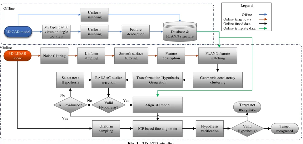
The algorithm consists of an online and an offline phase as presented in Fig. 1.
3.1. Offline phase
The input to the offline phase is a 3D CAD model point
cloud Pcad of the target to be recognized. From Pcad we
generate 80 partial views to simulate the input given by an imaging range sensor. Similarly to, [24] we generate partial views by placing a virtual camera around the target on a bounding sphere with a radius that encloses it. These partial views are used to generate the target keypoints and descriptors. Fig. 2 shows four examples of partial point cloud views of a T72 Main Battle Tank (MBT).
For processing efficiency, we uniformly subsample the partial views at a user-defined resolution. For simplicity, we do not use a keypoint detection strategy but describe all points of the subsampled point cloud with the SHOT descriptor. SHOT encodes information about the surface of a point cloud within a spherical support around a keypoint. This sphere is divided into 32 volumes, with eight divisions along the azimuth, two along the elevation and two along the radius. For every volume, a 1-dimensional local histogram is computed considering all points in the volume, which are properly grouped. The histogram variable is the cosine of the angle between the normal of the keypoint and the normal of the current point within the volume. SHOT uses a local reference frame tied to the surface normal of the keypoint, so that descriptors are invariant to rotation and translation. The surface normals and the encryption radius of SHOT are calculated at a user specifiable grid resolution.
Due to the large amount of points to be described, all descriptors are assembled into a Fast Library for Approximate Nearest Neighbors (FLANN) structure that will be used during the matching step.
We also store subsample Pcad under a different resolution
Offline
Online
Multiple partial views or single
top view
Uniform sampling
Feature description Uniform
sampling
3D LIDAR scene
Uniform sampling
Smooth surface filtering
Feature description
FLANN feature matching
Geometric consistency clustering Transformation Hypothesis
Generation RANSAC outlier
rejection Select next
Hypothesis
No No
Yes
Align 3D model
ICP based fine alignment Uniform
sampling
Hypothesis verification Database &
FLANN structure
Noise filtering
Yes
3D CAD model
All evaluated? Target not
recognised
Target recognised Valid
Hypothesis? Valid
Hypothesis?
Legend
Offine Online target data Online fused data Online template data
Fig. 1.3D ATR pipeline
3.2. Online phase
The input to the online phase is a scene point cloud 3
P
where each point of the cloud is represented as
( , , )T 1,
a a a a
P x y z a K , K is the total number of points.
The first pre-processing stage concerns noise filtering using a statistical outlier removal. Considering the time-critical nature of our application, our noise filtering algorithm calculates the average point cloud resolution. Then a query point that has a distance to its closest neighbor larger than the average mesh
resolution mr is labelled as noise and is therefore rejected.
The noiseless point cloud Pb is given by:
2 2 1
min( )
b a a j
P P P P mr
K (1)
with b a a j, [0, ] :K a j. Then we uniformly
subsample the noise filtered scene using a box grid filter and
we create a new point cloud ( , , ) ,T 1,
c c c c
P x y z c L .
3.3.1. Smooth surface filtering
After noise filtering, keypoints are also rejected based on their normal angle deviation compared to the normal of their surrounding keypoints. This strategy exploits the Local Reference Frame estimation of the SHOT descriptor [25].
Specifically, for a given keypoint Pc and radius
r
c, we extracta spherical volume p ii, [0,M],M<L. Then we calculate its
eigenvalues Cvj j j {0,1, 2}, where jis the j
th
eigenvalue of the weighted covariance matrixC, and vj is the
jtheigenvector.Cis given by [26]:
1 :
1
( )( )( )
( )
i
k
T
i i i
i i i d D
C D d p p p p
D d (2)
where di pi Pc 2, Dis the distance of the furthest point
i
p and p is the 3D centroid of the spherical volume encoded.
This weighted strategy assigns larger weights to the closest points in order to improve robustness to clutter [26]. Sign disambiguation for rotation invariance is achieved through selecting the sign of an eigenvector such as to render it coherent with the majority of the vectors it represents. This procedure is applied to the eigenvector associated with the
smallest eigenvalue defining thez-axis, which we consider as
the normal
c
P
n associated to the keypoint Pc:
{0,1, 2}: min( )
c
P j j j
n j Cv (3)
This procedure repeats for all scene points. Then, based on a
threshold , the following cost function defines whetherPcis
accepted or rejected as part of a greater smooth area:
( )
elsewhere
i
p c
accepted if n
P
rejected (4)
where ( )
i
p
n is the standard deviation of the normal of each
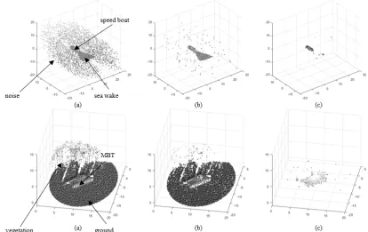
point within each spherical patch. Fig. 3 shows an example of the proposed noise and smooth surface filtering process. 3.3.2. Keypoint description, matching and consistency
checks
The vertices Pd Pc belonging to non-smooth regions are
[image:4.595.56.541.95.326.2]encoded by SHOT in the same manner as for the offline description of the model template.
We match a scene feature with all model features based on their Euclidean distance and a k-Nearest Neighbor Distance Ratio (k-NNDR) criterion. If the ratio of the nearest model
feature M
i
f with the k-nearest 'M
i
f is less than a threshold ,
then the scene feature S
i
f and the model feature M
i
f are considered as a match. This matching procedure iteratively continues for the k-nearest model-scene matches:
2
' 2
M S i j M S
i j M S i j
f f
f f NNDR
f f (5)
whereι,jare the feature indexes and k=10. In this paper, we
partially adopt [27] and set the k-NNDR threshold value to
τ=1. Although this value is large, this strategy reduces the
dependency between the threshold value and the metric used. Hence, the feature matching burden is partially shifted to a set of Geometric consistency checks [28].
For the first consistency check, the correspondences obtained from FLANN are clustered into hypotheses (instances of the model in the scene) using Geometric consistency. The latter aims at reducing mismatches by grouping correspondences into clusters that are geometrically consistent. Specifically, a list of descriptor correspondences is
created { M, S}
u u u
H p p , where M
u
p and S u
p are the model and
the scene correspondences from the FLANN matching stage:
,
M S M S u u u
H p p f f (6)
Given a seed correspondence from Hu, the first cluster is
initialized and all correspondences { M, S}
v v v
H p p , v <unot yet grouped that are geometrically consistent with the cluster
are added to it. The consistency check for a pair of
correspondencesHu, Hvis valid if:
2 2
|| M M || || S S ||
u v u v
p p p p (7)
εbeing the threshold tolerance for their consensus set.
3.3.3. Hypothesis generation and verification
Each cluster of correspondences validated by the Geometric consistency stage, defines a transformation hypothesis between the model and the target i.e. 6-DoF pose of the target within the scene. Although these hypotheses are based on correspondences twice refined for outliers (NNDR matches and geometric consistency checks), some outliers may still exist that are not consistent with a unique rigid transformation i.e. 3D rotation and 3D translation of the target within the scene. Therefore, we apply a third refinement stage based on the random sample consensus (RANSAC) algorithm that aims discarding the correspondences, which are inconsistent with the same transformation hypothesis.
After RANSAC, clusters that have a size less than a user-defined factor are rejected. For the remaining clusters, the transformation hypothesis (pose) is refined via the Iterative Closest Point (ICP) surface registration technique.
[image:5.595.84.498.100.361.2]Finally, a geometrical cue verification task is included to reject false transformation hypotheses while retaining the correct ones. During this stage, the template and the scene are aligned using the transformation hypothesis that passed all the intermediate consistency and outlier tests, on the subsampled full 3D template that is stored in the database during the offline stage. We note that during the hypothesis verification phase the un-processed scene is subsampled with different
Fig. 3. Examples of the proposed noise and smooth surface filtering (a) raw LIDAR detector point cloud (b) Noise filtered point cloud (c) Noise and smooth
parameters compared to the ones used during the keypoint description stage. The hypothesis is verified if the accuracy of the alignment is greater than a threshold as shown in the Hypothesis verification pseudo code (Algorithm 1).
4. Scenario Generation and Evaluation 4.1. Oktal SE synthetic environment
Real military LIDAR point clouds are classified, hence we create a number of simulated but highly credible air-to-ground and maritime missile engagement scenarios using the Oktal Synthetic Environment (SE) [29]. Oktal SE is a widely used highly realistic simulation software, capable of creating accurate active laser fingerprints that can be converted into point clouds for further processing. Models include both military and non-military objects to support the creation of a variety of scenes.
4.2. Scenario generation
Through Oktal SE, we simulate 7 scenarios in which a LIDAR based missile seeker observes both ground and maritime environments. Each scenario includes several runs resulting into a total of 410 scenes. Ground based scenarios involve urban, rural and industrial context while the missile is flying at various altitudes, headings and distances from a moving or a stationary target. Targets include main battle tanks and navy vessels depending on the nature of the scenario. We raise the difficulty of each scenario by increasing the amount of occlusion, adding clutter (non-target objects)
such as civilian cars, buildings, trees, etc. and creating scenes not containing a target at all. Finally, all scenarios are affected by the detector’s noise based on a model developed by SAGEM. The parameters per scenario are presented in Table 1, which in contrast to [7]–[9], [30] are more realistic and challenging as they are affected by a greater number of parameters.
4.3. Evaluation criteria
We use the following statistical measures:
True Positive Rate, which calculates the proportion of positive matches identified:
#TP #TP + #FN
TPR (8)
F1-SCORE, which encapsulates both precision and recall information in a single value:
2# 1
2 # # #
TP
F SCORE
TP FP FN (9)
Probability of detectionandProbability of false alarm:
#TP #scenes with target
d
P (10)
#FP
#scenes with hypothesis generated
fa
P (11)
Per trial the following cases can occur:
1. True Positive (TP): The algorithm provides a hypothesis for a scene image that includes a target and the
Euclidean distance based translational errorTerrorbetween the
ground truth target and the transformed model is less than 2-meters.
2. False Positive (FP): The algorithm provides a hypothesis for a scene image in which a target does not exist
or a target exists, butTerroris more than 2-meters.
3. True Negative (TN): The algorithm does not provide a hypothesis for a scene image in which a target does not exist.
Algorithm 1
Hypothesis Verification Pseudocode
1 functionHypothesis Verification
Input: aligned model (after ICP), scene i.e. input frame point cloud
Output: 100*(N/T) %
2 Foreach aligned model point 3 find the nearest scene neighbor
4 Count N= number of points with a squared nearest neighbor distance < threshold
5 Count T= total number of aligned model points 6 End
[image:6.595.52.540.125.298.2]7 Accept Hypothesis if Output > threshold
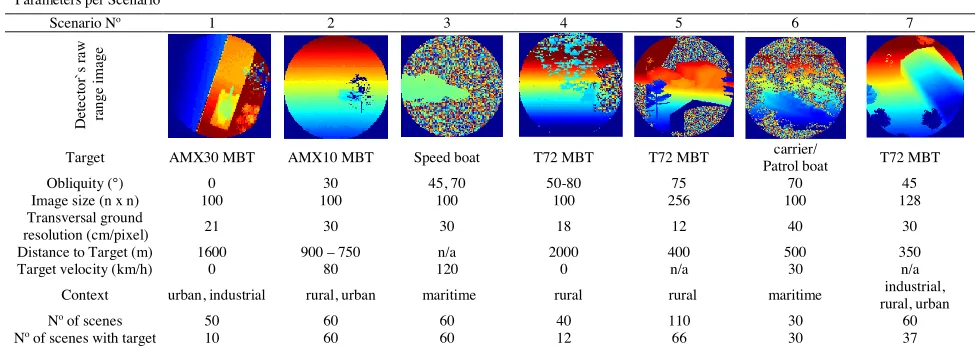
Table 1.
Parameters per Scenario
Scenario No 1 2 3 4 5 6 7
D
et
ec
to
r`
s
ra
w
ra
n
g
e
im
ag
e
Target AMX30 MBT AMX10 MBT Speed boat T72 MBT T72 MBT Patrol boatcarrier/ T72 MBT
Obliquity (°) 0 30 45, 70 50-80 75 70 45
Image size (n x n) 100 100 100 100 256 100 128
Transversal ground
resolution (cm/pixel) 21 30 30 18 12 40 30
Distance to Target (m) 1600 900 – 750 n/a 2000 400 500 350
Target velocity (km/h) 0 80 120 0 n/a 30 n/a
Context urban, industrial rural, urban maritime rural rural maritime rural, urbanindustrial,
Noof scenes 50 60 60 40 110 30 60
4. False Negative (FN): The algorithm does not provide a hypothesis for a scene image in which a target does exist. 5. Experiments
We train the suggested ATR architecture by splitting the runs of each scenario into a training and an evaluation subset with a ratio of 1:9. The overall performance attained is
Pd=88%, Pfa=9%, TPR=93% and F1-SCORE=92% while
detailed performance per scenario is presented in Fig. 4. Trials are implemented in MATLAB on Windows 7 on an AMD QL-64 CPU with 4GB RAM.
5.1. Scenario 1
This scenario concerns 50 industrial and urban ground based scene images and aims at investigating the performance under the case of a top-down view of a target with occlusion and clutter. It also investigates the behavior of our algorithm in the cases where no target exists in the scene. Indeed, ten of the scenes include the AMX30 MBT target while the rest have only clutter. Our algorithm exceled detecting correctly all ten
instances of the target achieving Pd=100%, Pfa=0%,
TPR=100% and F1-SCORE=100% (Fig. 4). 5.2. Scenario 2
A rural and urban ground based scenario is considered consisting of 60 scene images, all of them including the AMX10 MBT target. Compared to scenario 1, the current one is more challenging for the following reasons. First, the target is moving and affected by several objects from the scene in terms of occlusion and clutter altering heavily the MBT’s point cloud representation. Second, the absence of a gun barrel, which is a distinct feature of MBT’s and the smaller target size in combination with the larger transversal ground resolution. Third, the AMX10 MBT has many flat surfaces that are affected during the smooth surface filtering process.
Indeed, the flat surfaces of the AMX 10 MBT interfere with the normal estimation of the smooth filtering subroutine, and thus the target is partially filtered. Balancing surface filtering with ATR performance, while the target is affected by occlusion and clutter, is a puzzling operation. Considering this challenging situation, our ATR pipeline still manages to achieve a high ATR performance (Fig. 4).
5.3. Scenario 3
This refers to a maritime scenario including a speedboat at high speed, observed from medium and high obliquity angles. Main features that increase the difficulty of target detection and recognition in this scenario, are the extensive sensor noise, the small target size and the seawater’s albedo. Specifically, the seawater has a low albedo and thus a low reflectance providing a low Signal-to-Noise Ratio. Therefore, during the seeker’s peak mode detection phase the detector detects many false alarms in the range image, which are presented as noise artefacts. Adding to this challenge the small target size, the ATR problem becomes even harder.
In this scenario, the noise and smooth surface filtering modules highly contribute by improving the scene for our ATR algorithm. Nevertheless, in some scenes a few waves
close to the speedboat’s hull are not discarded influencing the
SHOT feature descriptor process. Even under these
circumstances, our ATR pipeline manages to achieve Pd=87%,
Pfa=5%, TPR=91% and F1-SCORE=93% (Fig. 4).
5.4. Scenario 4
This is an industrial and urban ground scenario consisting of 40 scene images, 12 which contain a T72 MBT. Main goal of this trial is investigating the performance of our pipeline under variable obliquity angles of 50°-80°. Pose independence is important for anti-tank missiles as they usually fly towards the MBT getting a downward but side-on or end-on view. In the late phase of engagement, they pop-up in order to perform a top attack where the armor is thinnest. Thus, the pose of the target that the LIDAR seeker observes changes when the target is very close compared to that seen at longer ranges.
Overall our ATR strategy almost excels with 10 true frames out of 12 with at least one true hypothesis and only 1 false
frame out of 28 achieving Pd=92%, Pfa=0% and TPR=92%
(Fig. 4). 5.5. Scenario 5
This is a rural ground based scenario consisting of 110 scene images, 66 of which include a T72 MBT target. The challenge of this scenario are the simultaneous larger scene image size, the lower scene resolution, the large obliquity and high noise level that increase even further the difficulty of the ATR task.
Considering this challenging situation, our ATR architecture
still achieves Pd=68%, Pfa=12% and TPR=74%. A detailed
performance plot is presented in Fig. 4, while Fig. 5 presents a TP and a FP recognition example. Balancing noise filtering with recognition performance, while the target is at higher resolution and affected by occlusion and clutter, is a very demanding process. It is worth noting that while current literature demonstrates SHOT’s robustness to point cloud down-sampling [18], [23], this trial highlights SHOT’s vulnerability to the up-sampling recognition case.
5.6. Scenario 6
This is a maritime scenario consisting of 30 scene images, 15 of which include an aircraft carrier vessel and 15 a patrol boat. Even though all scenes consider a high obliquity angle, our proposed algorithm excels by detecting correctly all targets
achieving Pd=100%, Pfa=0% and TPR=100% (Fig. 4).
5.7. Scenario 7
This is a mixed ground based scenario as it includes rural, urban and industrial scenes. It consists of 60 scenes, 38 of which include a T72 MBT target. The challenging features of this scenario are its non-smooth and non-random structured clutter objects and its larger scene image size. The former (non-smooth and non-random clutter) inhibit both our filtering processes from properly rejecting unwanted vertices. These clutter objects combined with the up-sampled resolution, raise even higher the difficulty of the ATR problem. Considering this challenging situation, our ATR pipeline still manages to
6. Single Template Scheme
The intended application is a future missile incorporating a LIDAR seeker and affording 3D ATR capabilities. In order to reduce the computational time, we investigate the extreme case of introducing a single template per target instead of multiple partial views. Although our multi-view proposal can be implemented on Field-Programmable Gate Arrays (FPGAs) we investigate the recognition performance by reducing the amount of template data to be stored. This concept is appealing as computational time and memory requirements to store the templates will reduce, while the utility of the proposed pipeline will extend for multi-sized templates.
During the offline stage, the input is a 3D point cloud CAD
model Pcad of the target to be recognized. A bottom-up
viewing orientation of the target is not applicable and
therefore we rejected the lower part ofPcadusing the Hidden
Point Removal (HPR) algorithm [31]. HPR comprises of three
phases. Initially, it remaps the coordinates of each point Pe
belonging to Pcad by exploiting an imaginary ray connecting
each point Pe and the viewpoint. The remapping is a mirror
image ofPcadas observed from the viewpoint that is set at the
missile’s LIDAR seeker. The next step incorporates the projection of the remapped point cloud onto a sphere of radius
Rcentered at the missile seeker, and the resulting point cloud
consisting of the Psfe points is given by:
2( ) e
sfe e e e
P
p P R P
P (12)
In this paper, Ris manually calculated. Finally, the convex
hull of Psfe associated with a weight factor
a
efor each pointbelonging to Psfeis given by:
| | | |
1 1
| ( : 0) 1)
sfe sfe
P P
e sfe e e
e e
a p e a a (13)
A point Pe of the raw point cloud is considered as visible,
only if its spherical flipped form Psfe is on the convex hull.
For the HPR we set the viewing point on top of the model and
select the appropriate radiusRsuch as to enhance the available
information extracted fromPcad. The resulting 3D point cloud
of the model PHPR is approximately the upper half of the
model as shown in Fig. 6.PHPRrepresents an incomplete 3D
model of the target, which is then entered to the pipeline presented in Fig. 1.
Our trials show that the single template strategy is faster to execute and the ATR performance is only minor reduced. The main reason is that during the offline stage, the SHOT
descriptor encodes a local area of thePHPR. On the contrary,
the point cloud of the target within the scene is only partially visible due to self-occlusion. Hence, we attempt to match
SHOT descriptors that are de facto not equal. Even in that
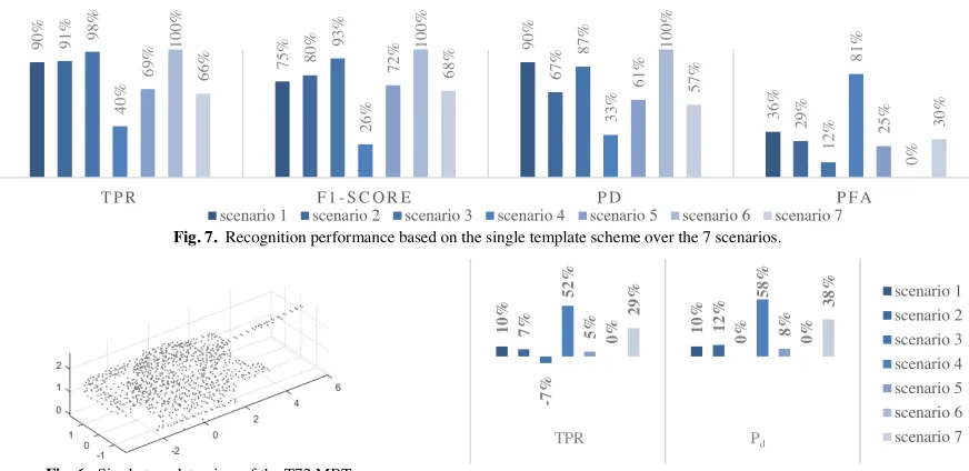
extremely challenging case, our suggested architecture is still an appealing ATR solution. Fig. 7 presents the single template recognition performance while Fig. 8 a performance comparison between the multi and the single template concepts.
On most scenarios the single template solution performs well with mostly minor recognition fluctuations. Considering the processing speedup it offers, this performance drop can be afforded. Specifically, on scenarios 1, 2 and 5 the recognition performance has an average drop of only 8%. For scenarios 4 and 7, the performance of the single template concept is quite affected. This is due to the highly unstructured and complex scenes, and the clutter military vehicles that affect the SHOT feature matching process. In fact, the complexity of the scenes in these scenarios combined with the single-pose template scheme, are so challenging that prohibit our ATR pipeline from bridging the gap between the corresponding SHOT descriptors of the template and the scene. Solutions to enhance
the ATR performance can be increasing the radius Rof the
HPR algorithm and the description radius of the
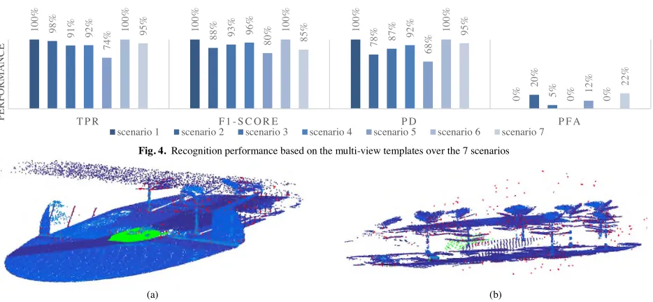
Fig. 4.Recognition performance based on the multi-view templates over the 7 scenarios
[image:8.595.68.535.95.311.2](a) (b)
Fig. 5.Examples of (a) successful and (b) unsuccessful ATR on a scene from scenario 5 (noise is not displayed for better viewing). In blue is the point cloud
scene, in red the remaining scene vertices after pre-processing and in green the transformed model template based on the Hypothesis generated
1 0 0 % 1 0 0 % 1 0 0 % 0 % 9 8 % 8 8 % 7 8 % 2 0 % 9 1 % 9 3 % 8 7 % 5 % 9 2 % 9 6 % 9 2 % 0 % 7 4 % 8 0 % 6 8 % 1 2 % 1 0 0 % 1 0 0 % 1 0 0 % 0 % 9 5 % 8 5
% 95%
2
2
%
T P R F 1 - S C O R E P D P F A
P E R F O R M A N C E
SHOT descriptor. These changes though will increase processing time because SHOT will have to encode more vertices for both the template and the scene. Processing time is a critical parameter for a missile platform and therefore the suggested improvement could be viable in a GPU processing scheme rather than a CPU one as we used in this work.
Interestingly, in scenario 3 the single template approach gains higher recognition rates compared to the multi one. This is due to the small and flat surfaces the speedboat consists of in combination with the severe noise level and the waves near the target’s hull. The former leads to extended target self-occlusion prohibiting the available multi-view templates to assist the recognition process. The remaining speedboat point cloud after self-occlusion is then affected by noise and the waves, further increasing the difficulty of the recognition process. Increasing the number of partial views beyond 80 would enhance the ATR performance but would increase the entire processing time and therefore is not investigated. On the contrary, the incomplete 3D model, regardless of the target’s pose inside the scene has still sufficient points to match.
The single template concept is appealing as it achieves good recognition performance levels while in parallel:
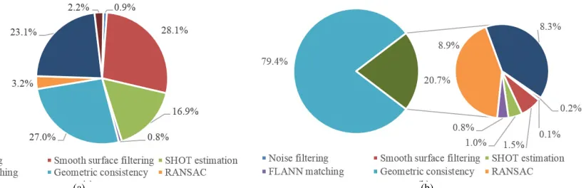
1. Compared to the multi template approach it affords a processing time speedup of x2.5 up to x75. The speedup varies as it depends on the number of Hypotheses tested. Hence, the single template approach requires 2s/scene while the multi-view 5 up to 60s/scene. For completeness, Fig. 9 presents the average computational time of each processing phase of our ATR architecture. For the single template case, the two filtering procedures (noise and smooth surface filtering) and the ICP refinement consume the vast computational time. For the multi-template case, Geometric consistency requires 79.4% of the total time. This computational burden is because Geometric consistency is an iterative process applied several times for each of the multi-view templates.
2. It gives to the proposed pipeline a dual role i.e. both for multi and single templates, which is outstanding.
3. The single template scheme requires on average
2.89Kb/model storage memory, while the multi
3,796Kb/model. 7. Conclusion
We present a fully automated target recognition solution appropriate for LIDAR based missile applications. The major contribution of this research is providing an architecture appropriate for future LIDAR based missile platforms. From a military and defense prospect, our contribution may be both appealing and significant for the following reasons:
1. We propose a high performing ATR pipeline that successfully handles the cases where the missile is at various altitudes, obliquities, distances to the target and scene resolutions.
2. Our pipeline is flexible in terms of conforming to the missile’s storage memory limitations. Indeed, even in the single template scheme the ATR performance of our pipeline is notable. This is important because regardless of the operational scenario, the same algorithm can be exploited while only the nature of the template varies (single vs. multi). The interchangeability of our ATR architecture becomes even more important in battlefield conditions where the preparation time to execute military operations is quite strict.
Although we focus on missile platforms, broader potential applications may include a great range of time-critical complex and intelligent systems for space, air and ground environments for military, law-enforcement, commercial, automotive and research purposes. Examples of applications may include aided target recognition for human operators under battlefield conditions/ homeland security, object recognition for drones, autonomous cars and robotic applications.
[image:9.595.86.522.97.309.2]Future work will focus on GPU/ FPGA implementation to improve further time efficiency to accommodate this approach to high-speed missile applications where the processing time requirement is higher.
Fig. 7.Recognition performance based on the single template scheme over the 7 scenarios.
9
0
%
7
5
% 90
% 3 6 % 9 1 % 8 0 % 6 7 % 2 9 % 9 8 % 9 3 % 8 7 % 1 2 % 4 0 % 2 6
% 33%
8 1 % 6 9 % 7 2 % 6 1 % 2 5 % 1 0 0 % 1 0 0 % 1 0 0 % 0 % 6 6 % 6 8 % 5 7 % 3 0 %
T P R F 1 - S C O R E P D P F A
P E R F O R M A N C E
[image:9.595.77.526.102.191.2]scenario 1 scenario 2 scenario 3 scenario 4 scenario 5 scenario 6 scenario 7
Fig. 6. Single template view of the T72 MBT Fig.8.Multi vs. Single template performance. Positive values favor Multi
template approach while negative the Single template
1 0 % 1 0 % 7
% 12%
-7 % 0 % 5 2 % 5 8 % 5
% 8%
0
% 0%
2
9
% 38% scenario 1
scenario 2 scenario 3 scenario 4 scenario 5 scenario 6 scenario 7
[image:9.595.297.522.213.301.2]Acknowledgements
This work is supported by the MCT ITP defense research program “3D Automatic Target Recognition Seekers and Architecture”.
References
[1] G. J. Gray, N. Aouf, M. a. Richardson, B. Butters, R. Walmsley, and E. Nicholls, “Feature-based recognition approaches for infrared anti-ship missile seekers,”Imaging Sci. J., vol. 60, no. 6, pp. 305–320, Dec. 2012.
[2] S.-G. Sun, “Automatic target recognition using boundary partitioning and invariant features in forward-looking infrared images,”Opt. Eng., vol. 42, no. 2, p. 524, Feb. 2003.
[3] L. Du, P. Wang, H. Liu, M. Pan, and F. Chen, “Bayesian Spatiotemporal Multitask Learning for Radar HRRP Target Recognition,”IEEE Trans. Signal Process., vol. 59, no. 7, pp. 3182– 3196, 2011.
[4] R. Paladini, M. Martorella, and F. Berizzi, “Classification of man-made targets via invariant coherency-matrix eigenvector decomposition of polarimetric SAR/ISAR images,”IEEE Trans. Geosci. Remote Sens., vol. 49, no. 8, pp. 3022–3034, 2011.
[5] D. Perissin and A. Ferretti, “Urban-target recognition by means of repeated spaceborne SAR images,”IEEE Trans. Geosci. Remote Sens., vol. 45, no. 12, pp. 4043–4058, 2007.
[6] M. Martorella, E. Giusti, A. Capria, F. Berizzi, and B. Bates, “Automatic Target Recognition by Means of Polarimetric ISAR Images and Neural Networks,”IEEE Trans. Geosci. Remote Sens., vol. 47, no. 11, pp. 3786–3794, Nov. 2009.
[7] S. Roy and J. Maheux, “Baseline processing pipelilne for fast automatic target detection and recognition in airborne 3D ladar imagery,”Autom. target recogntion XXI, vol. 8049, May 2011.
[8] A. Vasile and R. Marino, “Pose-independent automatic target detection and recognition using 3D laser radar imagery,”Lincoln Lab. J., vol. 15, no. 1, pp. 61–78, 2005.
[9] X. L. Xiaofeng Li, J. X. Jun Xu, J. L. Jijun Luo, L. C. Lijia Cao, and S. Z. Shengxiu Zhang, “Ground target recognition based on imaging LADAR point cloud data,”Chinese Opt. Lett., vol. 10, no. s1, pp. S11002-311005, 2012.
[10] C. Grönwall, “Ground object recognition using laser radar data: geometric fitting, performance analysis, and applications,” Linköping, Sweden, 2006.
[11] O. Kechagias-Stamatis, N. Aouf, and M. A. Richardson, “3D automatic target recognition for future LIDAR missiles,”IEEE Trans. Aerosp. Electron. Syst., vol. 52, no. 6, pp. 2662–2675, Dec. 2016.
[12] Y. Guo, M. Bennamoun, F. Sohel, L. Min, and W. Jianwei, “3D Object Recognition in Cluttered Scenes with Local Surface Features: A Survey,”IEEE Trans. Pattern Anal. Mach. Intell., vol. 36, no. 11, pp. 2270–2287, Nov. 2014.
[13] A. S. Mian, M. Bennamoun, and R. Owens, “Three-Dimensional Model-Based Object Recognition and Segmentation in Cluttered Scenes,”IEEE Trans. Pattern Anal. Mach. Intell., vol. 28, no. 10, pp. 1584–1601, Oct. 2006.
[14] V. M. Patel, N. M. Nasrabadi, and R. Chellappa, “Automatic target recognition based on simultaneous sparse representation,” in17th IEEE International Conference on Image Processing (ICIP), 2010, pp. 1377– 1380.
[15] W. M. Brown and C. W. Swonger, “A Prospectus for Automatic Target Recognition,”IEEE Trans. Aerosp. Electron. Syst., vol. 25, no. 3, pp. 401–410, 1989.
[16] R. M. Marino and W. R. Davis, “Jigsaw: a foliage-penetrating 3D imaging laser radar system,”Lincoln Lab. J., vol. 15, no. 1, pp. 23–36, 2005.
[17] G. J. Gray, N. Aouf, M. A. Richardson, B. Butters, and R. Walmsley, “An intelligent tracking algorithm for an imaging infrared anti-ship missile,” in Proc. SPIE 8543, Technologies for Optical Countermeasures IX, 2012, vol. 8543, p. 85430L–85430L.
[18] S. Salti, F. Tombari, and L. Di Stefano, “SHOT: Unique signatures of histograms for surface and texture description,”Comput. Vis. Image Underst., vol. 125, pp. 251–264, Aug. 2014.
[19] W. Armbruster, “Model-based object recognition in range imagery,” in Proceedings of SPIE, 2009, vol. 7481, p. 748102.
[20] A. Del Bimbo and P. Pala, “Content-based retrieval of 3D models,” ACM Trans. Multimed. Comput. Commun. Appl., vol. 2, no. 1, pp. 20– 43, Feb. 2006.
[21] H. Bay, A. Ess, T. Tuytelaars, and L. Van Gool, “Speeded-Up Robust Features (SURF),”Comput. Vis. Image Underst., vol. 110, no. 3, pp. 346–359, Jun. 2008.
[22] O. Kechagias-Stamatis and N. Aouf, “Histogram of distances for local surface description,” in 2016 IEEE International Conference on Robotics and Automation (ICRA), 2016, vol. 2016–June, pp. 2487– 2493.
[23] Y. Guo, M. Bennamoun, F. Sohel, M. Lu, J. Wan, and N. M. Kwok, “A Comprehensive Performance Evaluation of 3D Local Feature Descriptors,”Int. J. Comput. Vis., vol. 116, no. 1, pp. 66–89, Jan. 2016. [24] A. Aldomaet al., “Tutorial: Point Cloud Library: Three-Dimensional Object Recognition and 6 DOF Pose Estimation,”IEEE Robot. Autom. Mag., vol. 19, no. 3, pp. 80–91, Sep. 2012.
[25] F. Tombari, S. Salti, and L. Di Stefano, “Unique shape context for 3d data description,” inProceedings of the ACM workshop on 3D object retrieval - 3DOR ’10, 2010, p. 57.
[26] A. Petrelli and L. Di Stefano, “On the repeatability of the local reference frame for partial shape matching,” in 2011 International Conference on Computer Vision, 2011, pp. 2244–2251.
[27] A. Aldoma, F. Tombari, L. Di Stefano, and M. Vincze, “A Global Hypotheses Verification Method for 3D Object Recognition,” in Computer Vision--ECCV 2012, Springer, 2012, pp. 511–524. [28] H. Chen and B. Bhanu, “3D free-form object recognition in range
images using local surface patches,”Pattern Recognit. Lett., vol. 28, no. 10, pp. 1252–1262, Jul. 2007.
[29] “OKTAL Synthetic Environment.” [Online]. Available: http://www.oktal-se.fr/website/publications.php?topic=3. [Accessed: 09-Mar-2016].
[30] W. Armbruster, “Exploiting range imagery: techniques and applications,” in Symposium on Photoelectronic Detection and Imaging, 2009, vol. 7382, pp. 738203-738203–12.
[31] S. Katz, A. Tal, and R. Basri, “Direct visibility of point sets,”ACM Trans. Graph., vol. 26, no. 3, p. 24, Jul. 2007.
[image:10.595.120.531.103.235.2](a) (b)
Fig. 9.Processing time breakdown for the (a) single and (b) multi template scheme (best seen in color).