International Journal of Innovative Technology and Exploring Engineering (IJITEE) ISSN: 2278-3075, Volume-8 Issue-9, July 2019
Abstract: This paper presents a detailed discussion about single stage inverter to drive the multi-phase V/F induction motor to propel boat fed from stand-alone photovoltaic (PV) system, increases compactness, reliability and economical features to the entire system. To drive the boat using non-linear multi-phase induction motor from a non-linear PV source, under maximum power point condition is a tedious task. Though, single stage systems seem to simple, obtaining various control functionalities such as MPPT operation, model reference speed estimation, V/F speed control methods along with controller design and modulator functions from only one power electronics converter increases the design complexity to the designer.
While performing MPPT and speed estimation operations in closed loop, re-checking ability is integrated to the inverter fed V/F control induction motor initiative for superior exactness results improves the dynamic performance, and also energy saving to end-user. Closed-loop (CL) boat sailing operation with load torque and model reference adaptive based speed estimation using multi-phase induction motor model along with the MPPT P&O algorithm, is used to generate reference command to the controller, and designed controller ensure to track this reference by producing controller voltage to modulator. Simple Sine PWM is adopted for the generation PWM pulses to the inverter in this drive to enhance the design simplicity. Proposed method is simulated using MATLAB/SIMULINK and closed loop solution at both different irradiations and load torque conditions presented. The simulation marks illustration that planned method is inexpensive, efficient, performance is reliable and superior.
Index Terms: Photo Voltaic cell (PV), Maximum Power Point Tracking (MPPT), V/F control.
I. INTRODUCTION
The stress around availability of fossil fuels and the increasing needs of power, claim opposite interests societal and scientific revolution capable of bringing balance between two, development versus ecological concerns. Though benefits of electrical supremacy are known well, but the utilization of the electrical supremacy facing new encounters such as efficacy or harvest energy using renewable power sources. The most feasible solution to exclusively in extents wherever power is not up-to the spot is presentation of renewal energy sources like wind, solar, etc. with the issues stated, the electric propulsion (can be used in Electric road vehicle and total electric boats) is one relevant topic. Electric powered boat to carry tourists play vital role in preserving nature especially at tourist places. Higher efficiency renders less number of solar panels with associated reduction in cost and
Revised Manuscript Received on July 10, 2019.
Suribabu Yaramasu, Research Scholar, Dept. of EEE, University College of Engineering & Technology, Acharya Nagarjuna University, Guntur.
Chandra Sekhar Koritala, Professor, Dept. of EEE, R.V.R & J.C College of Engineering, Guntur.
weight. Growing tendency of using this class of transportation in urban and tourism perspective has been observed. PV fed water transport system is proposed with D.C. motors [1]. The advantages of D.C. motors are of virtuous vibrant act but high preliminary cost, requires frequent care, higher rating is restricted by commutation and efficiency relatively low. In recent years, efficient adjustable speed drives by variable voltage and frequency is receiving more attention. PV fed marine propulsion technology with three-phase induction-motor (IM) is effective clarification for water transport system as induction motor is rugged, cheap, necessitates low maintenance and efficiency high with optimum efficiency algorithm [2].
Two stage inverter in [3] is presented to control induction motor; while in [4] solitary stage individual PV system to pumping water is proposed. From [4], it is exposed that technology based on solitary stage inverter is higher than dual stage inverter. Recent proposals based on open end winding IM fed from twin inverter [5] is not cost effective. Standalone PV systems have widespread usage in distant area solicitations such as water impelling, electric boat (green boat) momentum. These standalone PV systems determined solicitations necessitates the reliable operation. However, 3φ IM is less reliable during fault conditions for standalone applications. Keeping of additional motor rating equal to main motor as stand by during fault conditions [6] is not cost-effective and correspondingly reasons added baggage. Due to progressions in power electronics and multi-phase induction motors, multi-phase drives becomes added prevalent for autonomous solicitation wherever great dependability process is vital. Undoubtedly multi-phase ac energies canister achieve its action even when stages are mislaid due to fault [7]. So in this paper a closed loop control of solitary stage standalone process of PV powered multi-phase induction motor drive boat is offered, which offering benefits of good dynamic concert, rugged, cost effective, ease of control of motor and fault tolerant operation etc. Integration of MPPT algorithm in planned system with V/F control which advances further recital of motor. Load torque and MPPT is feed to the switch which provides gate pulses to the inverter switches for forming closed loop operation. The solar PV array, MPPT, modelling of multiphase induction motor, CL planned arrangement is presented in section-II. The planned control process with schematic illustration is revealed in section-III. In section IV Simulation is done using MATLAB/Simulink and discussed. Finally in section V concluded the simulation results of proposed closed loop
system.
V/F based Multi-Phase Induction Motor Drive
For PV Powered Boat Applications
II. NOTATION
The notation used in the paper is stated below. Constants:
p Boltzmann constant Kg-m2/S2K q Electron charge in Coulomb Rs PV cell series resistance in Ohm ij Photo current in Ampere
io Diode saturation-current in Ampere J Movement of inertia Kg-m2
P Number of poles of machine
III. SYSTEM DEPICTION
The scheme for budget operational closed loop control system is proposed. Proposed system consists Solar PV array, P&O MPPT controller, multiphase IM, etc. The depiction of system is given below;
A. Solar PV array and characteristics
Practically, solar cell yields 0.7V which is not sufficient to custom in scheme. Solar-cell translates solar-energy in to
electrical-energy. So PV module is make by combination of number of cells are settled in series/parallel. Similarly, PV panel is make by linking amount of PV modules and PV array is sort by linking some panels. Electrical depiction of solar-cell is shown in the Fig.1.
D
D I phI ISH Rs
sh R
Irradiation
Temp
Fig.1 Electrical equivalent of Solar Cell
PV array characteristics are represented by following equation:
0( 1)
k pvcell L
i i i e (1)
and;
( pvcell pvcell s)
q v i R
k
npT
(2)
Where, ipvcell is PV cell current and vpvcell is PV cell voltage, T is operating temperature of panel in Kelvin.
Fig.2: Closed-Loop Speed Control of multiphase IM Using V/F cocept
B. MPPT
The need to track MPP in PV arrays is well known on account of drawbacks of PV arrays such as I-V characteristics are non-linear, life limited and initial cost is high. All these drawbacks make arrays to extract as much power as possible. Control algorithm name as MPPT is used to track the MPP from the PV source. MPPT is controlled through the PV voltage and power. Various MPPT algorithms have been proposed and available in literature. The hill climbing MPPT algorithm is most popular since it is simple, easy to implement in both analog and digital systems, accurate and robust. This is also called Perturb & Observe (P&O) algorithm presented in [8] anticipated by B.Bose.K et.al. The hill mounting technique is so named because of the nature P-V curve of PV array.
C. Dynamic Modelling of a Five-Phase Induction Motor Modelling is the way toward supplanting a machine with a lot of numerical conditions overseeing the function of machine. I.e., it is the concerning of the inputs and outputs by
course of mathematical equations [9]. Supply Voltage, Frequency and Torque demand by load are the inputs to five-phase Squirrel Cage Induction Motor (SQIM). Angular Speed & Electromagnetic Torque are the outputs of the apparatus. PPEC is used to design motor traditionally but it is not suitable to forecast dynamic behaviour of the motor. To obtain the dynamic performance of motor d-q classical is used. The basic purpose of using this approach is controlling the motor parameters independently such as torque and flux. Following section presents the development of model of 5φ IM in phase variable form and later d-q machine model is constructed.
C1. Phase Variable Model:
Ten phase windings, each span 36 degrees used to construct five-phase induction motor. Therefore, spatial displacement between phases is 720. It is presumed that rotor zigzagging is equivalent and denoted to stator winding. Then, 5φ IM related by the
International Journal of Innovative Technology and Exploring Engineering (IJITEE) ISSN: 2278-3075, Volume-8 Issue-9, July 2019
dt d i R s abcde s abcde s s abcde v r abcde sr s abcde s s
abcdeL i L i
(3)
dt d i R r abcde r abcde r r abcde v s abcde rs r abcde r r
abcdeL i L i
(4)
The succeeding meaning of phase voltages, currents and flux linkages smears to equations (3) and (4)
(5)
Here, xdenotes variable for voltages, currents, and flux linkages (v,i,) of both stator and rotor.
The matrix of stator inductances is given with (α=2π/5)
(6) Similarly, matrix of rotor inductances
(7) MI between stator and rotor windings are given with
(8) T sr rs L L
The angle θ denotes the immediate location of the rotor respect to stator. The matrices are
(9) Motor torque in phase variables form as
r abcde s abcde abcde rT abcde sT abcde abcde T e i i d L d i i P i d L d i P T 2 2 (10.a) r abcde sr sT abcde e i d L d i P T (10.b)Substitution of equations (4), (5) and (8) into equation (10.b) yields the torque equation:
(11)
C2. Model Transformation:
Power invariant transformation remove the time varying inductance terms to simplify the model. The following transformation matrix is applied to stator winding
(12) The transformation of rotor variables is performed using the same transformation expression, except θs is replaced by β, where θs-θ. Hence the rotor transformation matrix is
(13) The transformation angles for stator and rotor extents are linked to the arbitrary haste of the collective orientation edge:
adts
s
(a)dt (14)C3. Arbitrary Common Reference Frame model:
Relation between phase variables and variables in the transformed domain is given by
s abcde s s dq s abcde s s dq s abcde s s
dq A v i A i A
v
r abcde r r dq r abcde r r dq r abcde r r
dq
A
v
i
A
i
A
v
(15) Replacing equivalences (3) and (4) into equation (15) and the applying of equations (12) and (13) results the machine’s voltage equations in the common reference-frame where p=d/dt: dr qr a dr r dr ds qs a ds s
ds Ri p v Ri p
v ( )
qr dr a qr r qr qs ds a qs s
qs Ri p v Ri p
xr xr r xr xs
xs s
xs Ri p v Ri p
v
yr yr r yr ys
ys s
ys Ri p v R i p
v
r r r r s
s s
s Ri p v Ri p
v0 0 0 0 0 0
(16) Transformation of flux linkage equations (3) and (4) results in
ls
ds dr dr
lr
dr dsds L 2.5Mi 2.5Mi L 2.5Mi 2.5Mi
ls
qs qr qr
lr
qr qs qs L 2.5Mi 2.5Mi L 2.5Mi 2.5Mi xr lr xr xs
ls
xsL i L i
yr lr yr ys
ls
ysL i L i
r lr r s
ls
s L i0 0 L i0
0
(17) Introduction of Lm=2.5M allows equation (17) to be written in the following:
xr lr xr xs
ls
xs L i L i
yr lr yr ys
ls
ysL i L i
r lr r s
ls
s L i0 0 L i0
0
(18)
Finally, transformation of torque equation (10.b) yields
drqs dsqr
e Mi i i i
P
T
2 5
]
[
drqs dsqr me
PL
i
i
i
i
T
(19)The mechanical rotor motion equation is
dt d P J T
Te L (20)
The difference between a 3φ and 5φ machine classical deceits extra x-y set of workings which non-flux and non-torque are making mechanisms. Simply they add extra losses in the machine.
D. Closed loop V/F speed control
[image:4.595.52.284.638.751.2]CLSC with slip regulation enhances more development in presentation for OL V/F control. There numerous CL control techniques like scalar of V/F control, vector pitch leaning control and so on. Here we focus on two-level inverters based scalar control techniques to evaluate the performance of the drive. The scalar control closed-loop operation is explained in Fig. 2.
Fig.3: Speed shift for variation of (a) Voltage (b) Load Torque
To calculate the reference speed in the proposed system generated voltage (VPV) and current (IPV) by the solar PV system are used. Reference speed ωr* (command speed) is generated throughreference speed estimationblock as shown in Fig.2. In this, the sensed speed of machine (ωr) is equated with the ωr* and error produces the slip frequency (ωsl*) knack over a P-I controller. The slip signal is auxiliary to the response speed and creates the frequency and voltage knack. Among various speed control methods of an Induction Motor, V/F Control is the furthermost widespread use in trade solicitations as of its comfort of execution. It is often desired to operate the motor at the rated flux so as to run efficiently. In the V/F operation, as the desired voltage increases, operating frequency is also increased. This is done by changing the parameters in the PWM modulation of the reference wave and the carrier wave. The change is done in such a way that the scale of the stator flux is retained perpetual at the desired worth at the steady-state. Often times this strategy is called constant flux or scalar control because it focuses only on the steady-state dynamics of the system. For a constant air gap flux, the slip is relational to torque. Hence, the scheme deliberated as torque regulator within a loop of speed control. The machine either accelerate or decelerate within the slip limit.
This arrangement recompenses speed change for variations of both source voltage and load torque as enlightened in Fig. 3(a) and Fig. 3(b) respectively. At constant supply voltage, if TL increases from point 1 to point 2 on curve ‘a’ in Fig. 3(a), ωr will tend to decrease, but it will be compensated by accumulative the operating frequency as shown by curve ‘b’ in Fig. 3(a).
Similarly, if supply voltage decreases at constant torque TL (exposed in Fig. 3(b)), the functioning point 1 on curve ‘a’ in Fig. 3(b) tends to move to point 2 on curve ‘b’ in Fig. 3(b), so speed inclines to diminution. Though, the speed control-loop rise the frequency and drop in speed will be reinstated as shown on curve ‘c’in Fig. 3(b).
IV. SIMULATION AND RESULTS
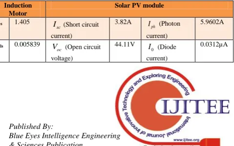
[image:4.595.312.552.679.829.2]In order to validate the proposed system, the total power circuit is modelled in MATLAB Simulink environment & the controller part is designed in Xilinx-ISE environment. 400V, 50Hz, 5HP, 5-ph induction motor is considered for the simulation purpose. To run this 5-ph induction motor in the simulink platform 4KW solar PV array is planned. BPSX140 solar PV module is considered for the simulation, and its parameters are shown in Table.1. Solar PV array used for electrical power cohort is erected with a cluster of 4 parallel strings of 24 succession linked modules.
Table-1: Data-sheet values of Solar-PV module
Induction Motor
Solar PV module
Rs 1.405
sc
I (Short circuit
current)
3.82A ph I (Photon
current)
5.9602A
Lls 0.005839
oc
V (Open circuit voltage)
44.11V
0
I (Diode current)
International Journal of Innovative Technology and Exploring Engineering (IJITEE) ISSN: 2278-3075, Volume-8 Issue-9, July 2019
Lm 0.1722
mpp
V (Voltage at
maximum power)
35.62 A (Diode factor)
1.30
Llr 0.005839
mpp
I (Current at maximum power)
3.595A s R (series resistance)
0.038Ω
Rr 1.398
s
N (No. of Series connected solar cells)
96
sh R (Shunt resistance)
993.5Ω
J 0.0131 Temperature Coefficients
P 4
i
K(Temperature Coefficient for current)
0.015% V K (Temperature Coefficient for voltage)
-0.21%
From the given datasheet values, unknown module parameters such as Rs, Rsh and diode quality factor A have
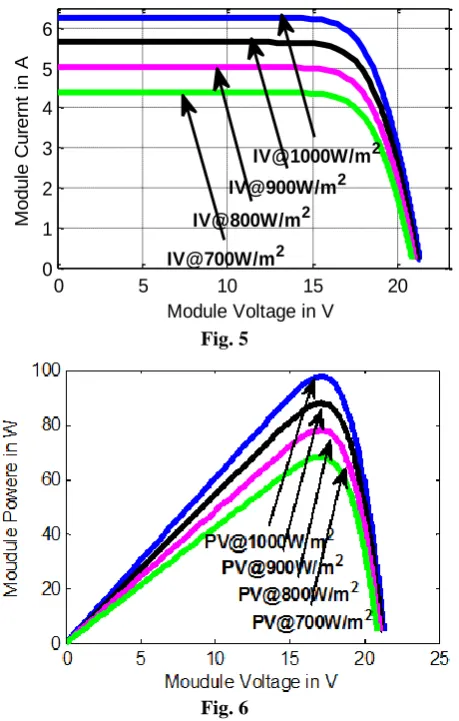
been estimated using “Newton-Raphson” iterative method. After efficacious abstraction of those strictures, solar-PV module as well as array is demonstrated in replication situation and their characteristics I-V and P-V have been corroborated with factual stint solar-PV module appearances gained over load test at dissimilar weather circumstances such as irradiation of 1000W/m2, 900W/m2, 800W/m2 and 700W/m2. It is vibrant that power impending from PV module / array / string is task of two sovereign strictures, namely, irradiation and temperature. These simulation results have been presented in Figures from 5 to 8.
0 5 10 15 20
0 1 2 3 4 5 6
Module Voltage in V
M
o
d
u
le
C
u
re
rn
t
in
A
IV@900W/m2 IV@1000W/m2
[image:5.595.43.295.50.193.2]IV@700W/m2 IV@800W/m2
Fig. 5
Fig. 6
Fig. 5 and 6: I-V and P-V Characteristics of PV module with change in irradiation respecively
0 5 10 15 20
0 1 2 3 4 5 6
Moudule Voltage in V
M
o
u
d
u
le
C
u
rr
e
n
t
in
A
IV@25oC
IV@30oC
IV@35oC
IV@40oC
Fig. 7
0 5 10 15 20
0 20 40 60 80 100 120
Module Voltage in V
M
o
d
u
le
P
o
w
e
r
in
W
PV@25oC
PV@25oC
PV@25oC
PV@25oC
Fig. 8
Fig.7 and 8: I-V & P-V Characteristics of PV-module with change in temperature respectively
[image:5.595.56.286.372.733.2]Fig.9: Module current, voltage and Power of PV Array
Fig.10: Load toque of induction machine
Fig.11: Reference and acrual speed of induction machine
Fig.12: Stator currents of induction machine V. CONCLUSION
This paper outlined discussion about stand-alone PV system fed single stage inverter to drive the multi-phase V/F induction motor to propel boat. Though driving the boat using non-linear multi-phase induction motor from a non-linear PV source, under maximum power point condition is a tedious task, obtained the required performance successfully. Achieved the desired performance while performing MPPT and speed estimation operations. Also validated the closed loop rechecking capability by incorporating it to the inverter fed V/F induction motor drive, and observed better accuracy decreases the run time of system as well as improves the
dynamic performance, and also results in energy redeemable to the end-user. The presented results shown that the planned closed loop method is economical, efficient, reliable performance, more fault tolerantand superior.
REFERENCES
1. Tiago. F., M. Duarte: Aspects of Modeling an Electric-Boat Propulsion System. IEEE, R8, Russia, July 11-15, (2010).
2. G.C.D.Sousa., D.S.L.Simonetti., E.E.C.Norena.: Efficiency optimization of a solar boat IM drive. 35th World Conference on IAEE (2000), Volume: 3 1424-1430.
3. A.Mathew, A.I. Selva kumar “MPPT Based Stand-Alone Water Pumping System” ICCCET2011, 2011.
4. E.Muljjadi, “PV water pumping with a PP tracker using a simple 6-step SWI,” IEEE Trans. on Indus. App., Vol.33, pp. 714–721, 1997. 5. Jain.S, TAK.Karamipur "A Single Stage PV System for a DIF Open-End
Winding IM Drive for Pumping Applications," Power Electronics, IEEE Trans., vol. 30, no.9, pp.4809-4818, 2015.
6. http: // navaltboats.com/navalt-products-solar-electric-ferry/
7. E.Leevi, “MPM for Variable speed applications”, Ind. Elect., IEEE Trans., 55, (5), 1893-1909, 2008.
8. Bose, B.K., Szezesny, P.M., and Steigerwald, R.L ‘Microcontroller control of residential PV-PCS, Ind. Appl., , IEEE Trans., 21(5), pp. 1182-1191, 1985
9. R.Krishnnan, “EMD Modeling Analysis and Control”, P. Hall 2001. 10. Ha.Abu-Rub., Atif Iqbal “HP Control of AC Drives with Matlab /