Design of Adaptive Fuzzy PI Controller for Electric
Vehicle with BLDC Drives
Soundarya G, Jayant Sharma, Karthikaikannan D, Balasundar C, Sundarabalan CK
Abstract: Electric vehicles in concern with its innumerable advantages, replaces the internal combustion engine vehicles (ICEV). The efficiency and performance of the Electric Vehicle (EV) depends mainly on the electric motor and its control technique. The Brushless DC (BLDC) Motor is used as the electric motor in the EV as it has high efficiency and high starting torque. The sensorless direct torque control technique is used to enhance the performance of the EV. The Adaptive Fuzzy PI (AFPI) Controller is the proposed controller in the EV. The comparison of reference torque and actual torque produce the error. It is applied to the AFPI controller which produces an output of reference torque. The EV with stationary reference frame theory of direct torque control with AFPI controller is simulated using MATLAB/SIMULINK.
Keywords: Adaptive fuzzy PI controller, Battery, BLDC motor, Direct torque control, Electric vehicle
I. INTRODUCTION
The electric vehicles are the prime future due to the foremost crisis of fuel scarcity. There are numerous advantages of EVs over conventional ICEVs. The EVs does not affect the environment as it works on electric motor rather than the consumption of fossil fuels. Evidently, it does not emit greenhouse gases. EV does not root to noise pollution [1]. Moreover, the performance of EVs overthrows ICEVs. The EVs has greatest advantages of extreme speed operation and control, smoothness, swiftest control. The EV comprises of a battery pack system which delivers the power to the whole vehicle [2]. The vital portion of the vehicle is the motor. The chief portion of the system which is responsible for the perfect operation of the EV is the controllerAn inverter is employed in this structure whose gate pulses are controlled according to the variations in the system. The EV manufactures prefer brushed DC motor or induction motor or BLDC motor. The construction of the rotor with permanent magnets improves its performancewhen compared to the other motors.
Revised Manuscript Received on September 07, 2019
* Correspondence Author
Soundarya G, School of Electrical and Electronics Engineering, SASTRA Deemed University, Thanjavur, Tamil Nadu, India.
Jayant Sharma, School of Electrical and Electronics Engineering, SASTRA Deemed University, Thanjavur, Tamil Nadu, India.
Karthikaikannan D, School of Electrical and Electronics Engineering, SASTRA Deemed University, Thanjavur, Tamil Nadu, India.
Balasundar C, School of Electrical and Electronics Engineering, SASTRA Deemed University, Thanjavur, Tamil Nadu, India,
*Sundarabalan CK, (Corresponding Author) School of Electrical and Electronics Engineering, SASTRA Deemed University, Thanjavur, Tamil Nadu, India,
The stator which has windings is commutated electronically. Elimination of brushes, led to less maintenance of BLDC motor [3].Moreover, its efficiency is very much higher to the order of 85% - 90% with a smaller size and less weight. It has smooth and swift operation at fluctuating speed and road conditions. So, the control mechanism is quicker and trouble-free. When comparing with other motors, BLDC motor shows superior performance ss[4].The controller determines the performance of the EV. It has to be designed precisely. According to the road condition and taking traffic into accountability, the speed of EV varies widely. So, for operating the motor in wide speed range, the direct torque control system is preferable [5]. Conventionally, Proportional Integral (PI) controller is used due to its simplicity and robustness. But, the intelligent method [6] of controlling will provide better control over PI controller.
The EV with BLDC motor is opted here. The Adaptive Fuzzy PI (AFPI) controller is used for the sensor less direct torque control technique. The operation of EV with BLDC motor and AFPI controller is simulated using MATLAB software.
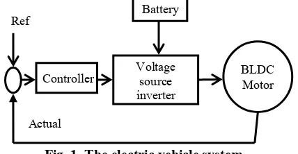
[image:1.595.324.538.541.652.2]II. MODELINGOFELECTRICVEHICLE Figure 1 shows the electric vehicle system. It comprises of a battery supplying the motor via the voltage source converter. The controller controls the BLDC motor. It uses the error value from the difference between the reference and actual value. The controlling parameters can either be torque or speed. Conventionally, PI controller is used. But intelligent techniques will provide precise control when compared to PI controller.
Fig. 1. The electric vehicle system
The BLDC motor has a trapezoidal back EMF. BLDC motor has better efficiency, higher starting torque. Usually, a hall effect sensor is attached to the motor to sense the position of the rotor. But there are more ripples in the torque which causes the motor torque cogging and the waveforms will be imperfect [9]. So, the sensor less direct torque control technique is designed in [8].
Voltage source inverter
BLDC Motor Battery
Ref
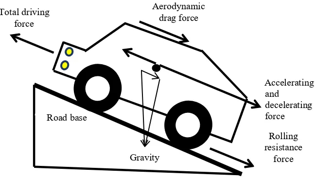
Fig. 2. The several forces acting on the EV
The EV modeling plays a significant role. It should be modeled prudently and precisely. While designing the EV, various factors like road condition, load variation, balancing and the forces acting on the vehicle [10]. Figure 2 shows the several forces acting on the EV.
A. Aerodynamic Force
The vehicle friction creates a force when moving through the air. This force is the aerodynamic force which is taken into account for the modeling of EV.
(1)
Where, is the velocity of the driving vehicle, is the frontal area of the EV, represents the air density on a free stream, is the coefficient of air.
The aerodynamic torque produced is:
(2)
Where, represents the radius of the tyre. B. Rolling Resistance Force
The tyres rolling on the road creates the rolling resistance. The bearing and gearing systems also produces friction which is also taken into account. The rolling force is directly proportional to the weight of the vehicle. The rolling force on the tyre is:
(3)
Where, is the mass of EV, represents the gravity acceleration and denotes the coefficient of rolling
resistance.
The rolling torque is given by:
(4)
C. Hill Climbing Force
The EV requires a force to climb on the slopes and hilly roads. The weight of the EV acts along the sloppy road.
(5)
The slope torque is given by:
(6)
D. Acceleration Force
The force generated due to acceleration of the EV also gets added to the total force acting on the EV.
(7)
The dynamic model of the EV and the force that controls the vehicle and its wheel kinetics is given by:
(8)
(9)
This force F produces torque to the EV motor which is given by,
(10)
Where, T is the torque of the motor of EV, is the
radius of the tyre of EV and G is the gearing ratio.
E. Modeling of Battery
The Li-ion battery pack is used to supply the motor and several other components in the EV. The batteries are connected in series and parallel combination for storage of energy according to the EV design. State of charge (SOC) and the terminal voltage Vb are the important parameters which are given in the
equations below:
Accelerating and
decelerating force Aerodynamic
drag force Total driving
force
Gravity Road base
Rolling resistance
(11)
(12)
Where, VO-open circuit voltage of the battery Rb- Internal resistance of the battery ib- Battery charging current
K - Polarization constant Q - Battery capacity A - Exponential voltage B - Exponential capacity
(13)
Where, is the energy required from the battery,
is the Discharge path efficiency, is the number of
cells in series in one battery, is the average voltage of
the cell in the course of discharge, is the Depth Of
Discharge that is allowed to the maximum, is the total
number of batteries connected in parallel.
F. Modeling of BLDC Motor
The trapezoidal back emf with 1200 conduction angle is given by the equations shown below.
(14)
(15)
(16)
(17)
The electromagnetic torque generated by the BLDC motor is given by:
(18)
Where, are the currents in the stator,
are the line voltages of phases a and b, band c,
are the back EMF voltages of phases a, b and c, represents the number of pole pairs, R represents the resistance of the stator, L and M denotes the self and mutual inductances of the stator.
III. CONTROL STRATEGIES A. Direct torque control of BLDC motor
The state space equations which are in α-β axis is transformed into stationary reference frame is given by:
(19)
(20)
The generated electromagnetic torque is given by:
=
(21)
Where, is the rotor electrical angle, are the
vector components of the rotor flux in α-β reference frame,
are the stator currents in α-β reference frame.
The stator and rotor flux equations are:
(22)
Where, are the vector components of stator
currents in d-q reference frame, are the stator inductances in d-q reference frame, are the flux
linkages in stator in d-q reference frame and , are the
flux linkages in rotor in d-q reference frame.
(23)
where,
(24)
(25)
Where, is the flux of the rotor and is the vectors of the back EMF, is the angular phase of the back EMF.
The difference in phase between the stator current vector and back EMF vector is given by,
(26)
Where, is the angular phase of the stator current
vector.
In α-β reference frame, the stator current vector
components are reformed by:
(27)
(28)
From the above equations, the electromagnetic torque is given by:
(29)
Table-1: Vector selection for direct torque control
Tl
330o-30o 30o-90o 90o-150o 150o-210o 210o-270o 270o-330o
0 1 V2(001001) V3(011000) V4(010010) V5(000110) V6(100100) V1(100001) -1 V5(000110) V6(100100) V1(100001) V2(001001) V3 (011000) V4(010010)
B. Adaptive Fuzzy PI Controller
The proposed controller is the Adaptive Fuzzy PI (AFPI) controller is a blend of Fuzzy logic controller and PI controller. It is capable of providing better performance and precise control over the BLDC motor when comparing with the PI controller. The triangular membership functions (MSF) [7] with 7 sets each in error, change in error and the output. Figure 3 shows the MSF of error, change in error and the output.The MSF are DH (Depreciate Huge), DI (Depreciate Intermediate), DT (Depreciate Tiny), NT (Neutral), AT (Appreciate Tiny), AI (Appreciate Intermediate)and AH (Appreciate Huge). The centroid method is used in defuzzifier module to estimate the output of this FLC.The rule base for the controller is shown on Table II.
(a)
(b)
(c)
Fig. 3. The MSF of a) Error b) Change in error c) output
Table-II: Rule base for the controller E/C
E
DH DI DT NT AT AI AH
DH DH DH DH DH DI DT NT
DI DH DH DH DI DT NT AT
DT DH DH DI DT NT AT AI
NT DH DI DT NT AT AI AH
AT DI DT NT AT AI AH AH
AI DT NT AT AI AH AH AH
AH NT AT AI AH AH AH AH
IV. SIMULATION AND RESULTS
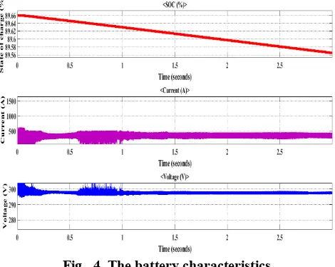
[image:4.595.310.545.197.384.2]A 140 kW, 15000 rpmBLDC motor with a torque of 340 Nm is designed. The Li-ion battery pack with a capacity of 65 kWh is used to supply the EV BLDC motor. The battery characteristics during the working of the EV are shown in figure 4.
Fig. 4. The battery characteristics
[image:4.595.308.546.520.676.2]The BLDC motor is supplied through the battery via a three phase inverter. The reference speed and the actual speed are compared and produce an error. This error and change in error are given as input to the AFPI controller.With the references from the torque and flux the reference currents are computed from the line currents of the BLDC motor. Then the PWM pulses through a three phase regulator. Figure 5 shows the torque, speed and power of BLDC motor.
Fig. 5. The torque, speed and power of BLDC motor
For the attainment of the torque-speed characteristics in an extended range, the amplitude and the phase of the current are changed whenever the flux weakening is essential.
The EV is designed with BLDC motor and the battery pack which supplies the necessary power to the motor. The direct torque control technique with stationary reference frame is used. The AFPI controller is used to produce the reference torque. It provides precise control over the EV and helps in maintaining the EV’s performance at all conditions.
ACKNOWLEDGEMENT
The authors would like to thanks SASTRA Deemed University for providing the facility to perform this work.
REFERENCES
1. B. Frieske, M. Kloetzke and F. Mauser, "Trends in vehicle concept andkey technology development for hybrid and battery electric vehicles," 2013 World Electric Vehicle Symposium and Exhibition (EVS27), Barcelona, 2013, pp. 1-12.doi: 10.1109/EVS.2013.6914783 2. M. R. Rade, "Design and Development of Hybrid Energy Storage
System for Electric Vehicle," 2018 International Conference on Information , Communication, Engineering and Technology (ICICET), Pune, 2018, pp. 1-5.doi: 10.1109/ICICET.2018.8533757
3. H. S. Hameed, "Brushless DC motor controller design using MATLAB applications," 2018 1st International Scientific Conference of Engineering Sciences - 3rd Scientific Conference of Engineering Science (ISCES), Diyala, 2018, pp. 44-49.doi: 10.1109/ISCES.2018.8340526
4. Y. Yang et al., "Design and Comparison of Interior Permanent Magnet Motor Topologies for Traction Applications," in IEEE Transactions on Transportation Electrification, vol. 3, no. 1, pp. 86-97, March 2017.doi: 10.1109/TTE.2016.2614972
5. S. B. Ozturk, W. C. Alexander and H. A. Toliyat, "Direct Torque Control of Four-Switch Brushless DC Motor With Non-Sinusoidal Back EMF," in IEEE Transactions on Power Electronics, vol. 25, no. 2, pp. 263-271, Feb. 2010.doi: 10.1109/TPEL.2009.2028888 6. James M. Keller; Derong Liu; David B. Fogel, "Fuzzy Relations and
Fuzzy Logic Inference," in Fundamentals of Computational Intelligence: Neural Networks, Fuzzy Systems, and Evolutionary Computation , , IEEE, 2016, pp.
7. Mircea Eremia; Chen-Ching Liu; Abdel-Aty Edris, "Fuzzy Systems," in Advanced Solutions in Power Systems: HVDC, FACTS, and Artificial Intelligence , IEEE, 2016, pp.doi: 10.1002/9781119175391.ch17
8. S. Chen, W. Sun, K. Wang, G. Liu and L. Zhu, "Sensorless High-Precision Position Correction Strategy for a 100 kW@20000 r/min BLDC Motor With Low Stator Inductance," in IEEE Transactions on Industrial Informatics, vol. 14, no. 10, pp. 4288-4299, Oct. 2018.doi: 10.1109/TII.2018.2793947
9. X. Zhou, X. Chen, C. Peng and Y. Zhou, "High Performance NonsalientSensorless BLDC Motor Control Strategy From Standstill to High Speed,"in IEEE Transactions onIndustrial Informatics, vol. 14, no. 10, pp. 4365-4375,Oct. 2018.doi: 10.1109/TII.2018.2794461 10. F. Naseri, E. Farjah and T. Ghanbari, "An Efficient Regenerative
Braking System Based on Battery/Supercapacitor for Electric, Hybrid, and Plug-In Hybrid Electric Vehicles With BLDC Motor," in IEEE Transactions on Vehicular Technology, vol. 66, no. 5, pp. 3724-3738, May 2017.doi:10.1109/TVT.2016.2611655
AUTHORSPROFILE
Soundarya G received her B.E. degree in Electrical and Electronics Engineering from Anna university, Chennai, Tamilnadu, India, in 2013, and M. Tech degree in Power Systemsfrom SASTRA Deemed University Thanjavur, Tamilnadu, India in 2019. Her main research interests include Power Quality, Renewable Energy system and Fuzzy Logic Controllers.
Jayant Sharma completed his B.E. from RGTU, Bhopal and M.Tech. from NIT Rourkela. Currently he is working as assistant professor in SASTRA Deemed University in Thanjavur, Tamilnadu, India.
D. Karthikaikannan received B.E., degree in Electrical and Electronics Engineering from Madras University in 2002. M.E., from Annamalai university in 2005 and Ph.D from Anna University Chennai. At present he is working as Assistant Professor in School of Electrical and Electronics Engineering, SASTRA Deemed University, Tanjore. His fields of interest are optimal power flow, automatic generation control and power system restructuring.as a reviewer of various IEEE and other reputed journals.
Balasundar C received his Bachelor of Engineering degree in Electrical and Electronics Engineering from Anna University, Chennai, Tamilnadu, India, in 2012, and Master of Engineering degree in Electrical Drives and Embedded Control from Anna University, Chennai, Tamilnadu, India, in 2015. He is currently a full time Ph.D. Research scholar in the School of Electrical and Electronics Engineering at SASTRA Deemed University, Thanjavur, Tamilnadu, India.