Abstract—The function of a power transformer defensive transfer is to work rapidly during the issue condition and to square the stumbling during the other working states of the power transformer. Another method for arranging transient miracles in power transformers, which can be executed in advanced handing-off for transformer insurance. Separation among various working conditions (Transformer, external fault) Power transformer is accomplished by incorporating waveform transformations along the neural network. The waveform change intensity transformer is connected to the transient miracle probe, as a result of its capacity to remove data from the transient sign all the while in both time and recurrence area. The nervous system is used in light of its self-learning and exceptionally non-linear mapping capability. The proposed scheme has been accepted through artificial neural network (ANN) designs. ANN engineering was designed to use BPN (back propagation calculation) alone, and BPN was consolidated with waveform transform (WNN), so it ought to perceive and order all the above working conditions and blames. The reenactment results got demonstrates that the new calculation precisely gives high working affectability to inside issues and stays stable for other working states of the power transformer. From that it was gathered that the consolidated WNN gives increasingly precise outcomes and it has fast reaction and expanded capacity to separate even low-level deficiency signals from other working conditions.
Keywords— Power transformers, bruises, artificial neural networks, wavelets.
I. INTRODUCTION
As of late, power transformers are one of the most important classes of equipment in the electric power structure, and transformer insurance is a basic piece of the protection process of the general framework. security procedure. The plan of defensive transfer needs to think about different nonlinear impacts, which may cause glitch of the hand-off supplies. The most well-known technique for transformer insurance uses the rate differential transfer as the essential assurance. Segregation between an interior shortcoming and other working conditions, For example, upon excitation of charge, over excitation, CT immersion is regarded as a difficult power transformer safety issue. The second symphony boundary-dependent traditional strategy
Revised Manuscript Received on September 10, 2019.
M Vijay Karthik, Electrical & Electronics Engineering Department, PhD Scholar, Noida International University, Greater Noida, U.P & Assistant Professor, CMR Engineering College, Hyderabad, Telangana, India.
(Email: [email protected])
Dr.Priyanka Chaudhary, Electrical & Electronics Engineering Department, Assistant professor, Noida International University, Greater Noida, U.P (Email :[email protected])
Dr. A Srinivasula Reddy, Electrical & Electronics Engineering Department, Principal, CMR Engineering College, Hyderabad, Telangana, India.
(Email: [email protected])
has greater intensity on excitation affecting intrinsic deficiencies, affecting current, CT immersion and solidity of the transformer in this way. Option improved insurance strategies dependent on transient location were created for precise and productive separation. Late ANN processes have been added for power transformer protection in light of the exceptionally non-direct mapping highlight capability. As it may be, the extraction process in these proposed strategies either relies on time or the repetition of space signals, yet it turns out to be essential to extricate both time and recurrence highlights of the sign for precise separation between an inward shortcoming and other working conditions. In addition to improve framework execution an effective investigation of high recurrence and brief span occasions must be finished. Consequently wavelet change is picked for investigating power transformer drifters on account of its great capacity to separate data from the transient flag regarding both time and recurrence area.
The wavelet change is a generally new and amazing asset in the examination of intensity transformer transient marvels as a result of its capacity to remove data from the transient flag at the same time in both time and recurrence space. As of late wavelet change have been connected to examine the power framework drifters just as shortcoming area and flaw identification issues. Waveform change and ANN were progressively associated in power framework applications, especially in isolation of diverse transient miracles in power transformers.
The system is an internal issue and separation between other working states of the power transformer by connecting waveform changes with the nervous system. In this proposed strategy, the waveform transform is correctly connected to break the differential current signal of the intensity transformer framework, each one in the progression of the waveform wave parts consisting of a particular repetition band. At that point neural system is intended to group outer shortcoming from Inrush states of the power transformer.
The basics of the paper start with the concepts of the transformer [12].It also give the Inrush current concepts [3, 4, 9] and the relations between the magnetic flux and the inrush current [8]. The Power system disturbances are briefly discussed along with their mitigation techniques[5]. The transformer modelling [10] gives the basic equations of a transformer. The wavelet transforms [2, 6, 7] are used to decompose the given input current signals and given as input to ANN to train. The ANN algorithm [5, 6] is used to
Artificial Intelligence Based Discrimination of
Transformer Inrush and External Fault Currents
Artificial Intelligence Based Discrimination of Transformer Inrush and External Fault Currents
train the given input and get the required output. The circuit description chapter it gives the full details about the circuits [1] regarding the simulation. In this different types of external faults [11] are simulated like L-G fault, L-L fault, 3 – Φ faults.
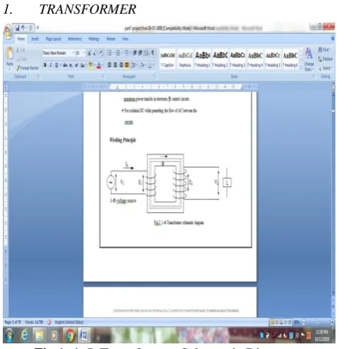
[image:2.595.55.297.116.365.2]1. TRANSFORMER
Fig 1: 1-Φ Transformer Schematic Diagram
The schematic diagram of a Transformer can be represents as in Fig1. One loop is associated with a wellspring of rotating voltage, an exchanging transition is arrangement in the overlaid center, which is connected with the other curl in which it produces EMF as indicated by Faraday's laws of electromagnetic acceptance standard.
Consider a transformer whose optional is pen and whose essential is associated with sinusoidal exchanging voltage V1. This potential contrast causes a rotating current Iμ to stream in the essential. Since the essential loop is simply inductive and the optional is open, the essential draws the polarizing current Iμ as it were. The capacity of this current is just to polarize the center. It is little in size and slacks V1 by 900. This exchanging current Iμ produces a transition Φ which is relative to the current and is in stage with it.
This adjustment in motion is connected with both essential and auxiliary windings. Therefore it produces self-incited EMF in essential and shared actuated EMF in optional. Oneself actuated EMF of essential at each moment equivalent to and contrary to V1. Thus the commonly initiated EMF in the optional is in antiphase with V1 .
The RMS estimation of incited EMF in the essential winding is
E1 = 4.44 f Φm N1
= 4.44 f Bm A N1 ---(2.2)
Similarly the RMS value of induced EMF in the secondary winding is
E2 = 4.44 f Φm N2
= 4.44 f B A N ---(2.3)
Where f = recurrence of the AC input (Hz)
Φm =Maximum transition in the center (Wb) Bm x A
Bm =Maximum transition thickness A =Area of cross segment
N1 = Number of turns in essential winding N2 = Number of turns in auxiliary winding
[image:2.595.324.483.208.427.2]When the Transformer is on no load the primary Input current is not wholly reactive. It needs to supply iron misfortunes in the center for example Hysteresis and Eddy current misfortunes. Consequently the No-heap essential current I0 isn't 900 behind V1 yet slacks by a point Φ0 < 900.
Fig 2: Phasor diagram of an unloaded transformer
Il = I0cos (Φ0) ---working component Iμ = I0sin (Φ0) ---magnetizing component I0 = √ Iμ2 + Il2
Inrush current is portrayed as the extent of prompt current drawn by a line-recurrence control transformer at the time the center is empowered. Transformer inrush flows are drawn by the high immersion of the iron center during the exchanging in of the transformer.
Fig 3: Transition versus current bend in a transformer center
Residual flux in the core at the moment of switch on, increases inrush current.
[image:2.595.312.547.553.686.2]Fig 4:Flux Versus current bend in a transformer center with leftover transition
The significant hotspots for Harmonics in Inrush Currents 1. Non-Linearity of Transformer center
2. Saturation of CT
3. Over excitation of the Transformers because of dynamic over voltage condition
4. Core remaining polarization 5. Switching moment
So inrush flows are oftentimes experienced during the exchanging procedure of transformers. Greatness of inrush current is relied upon the exchanging edges, exchanging time, size and extremity of lingering flux. The starting estimation of this inrush current is primarily dictated by the purpose of voltage wave at which exchanging in happens, however it is likewise incompletely subject to extent and extremity of leftover transition, which might be left in the center after past exchanging out. This remaining motion is impact by transformer center material trademark, center hole factor, winding capacitance, electrical switch, hacking qualities and different capacitances associated with the transformer.
Impacts of Inrush flows: 1. Breaker interferences
2. Failure of essential circuit segments, for example, switches
3. High inrush flows likewise require over estimating of circuits
4. Injection of clamor
5. Distortion once more into the mains
2.2 Disturbances in Power Systems:
The voltage provided by the utility framework ought to be an ideal sine wave with no sounds at its ostensible recurrence of 50 Hz and its ostensible extent.
Voltages can essentially leave from the perfect conditions because of the electrical cable unsettling influences.
1) Over Voltages: The voltage size is considerably higher than its ostensible incentive for a continued time of a couple of cycles.
2) Under Voltages: The voltage size is considerably lower than its ostensible incentive for a supported time of a couple cycles.(brownout)
3) Outages: The utility framework voltage crumples for a couple of cycles or more.(blackout)
4) Voltage Spikes: These are superimposed on the ostensible recurrence waveforms and happen once in a while.
5) Chopped voltage waveforms: This alludes to an individual cleaving of the voltage waveforms.
6) Harmonics: A mutilated voltage waveforms contains symphonious voltage parts at consonant frequencies. These music exists on a continued premise.
7) Electromagnetic Interference: This alludes to high recurrence clamor, which must be led on the electrical cable or emanated from its source.
2.3 Causes and Effects for Disturbances:
Sources that produce the unsettling influence are exceptionally differing. Over voltages might be brought about by unexpected lessening in the framework load, therefore making the utility voltage go up. Under voltages might be brought about by over-burdening condition, by beginning of Induction engine and so on. Enormous voltage spikes might be a consequence of exchanging in or out of the power factor redress capacitors, electrical cables and so on. Air conditioning to-dc line recurrence thyristor converter may cause cleaving of the voltage waveforms.
The Voltage sounds might be brought about by attractive immersion of the power framework transformer, symphonious flows infused by power electronic burdens and so forth. Electromagnetic Interference is delivered by most power gadgets hardware because of fast exchanging of the voltage and flows.
The impact of such electrical cable unsettling influences on the touchy gear relies upon the accompanying elements:
1. Type and Magnitude of the electrical cable unsettling influence.
2. Type of the hardware how well it is structured. 3. If any power moulding hardware is utilized or not.
II. TRANSFORMER MODELLING
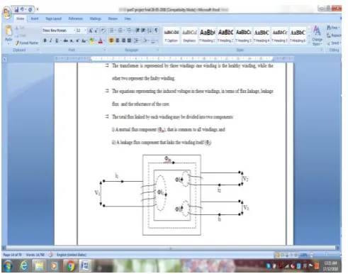
The transformer is represented by three windings one winding is the sound winding, while the other two speak to the defective winding. The conditions speaking to the initiated voltages in these windings, as far as motion linkage, spillage transition and the hesitance of the core. The absolute motion connected by each winding might be partitioned into two segments:
I) A shared motion segment (Φm), that is normal to all windings, and
Artificial Intelligence Based Discrimination of Transformer Inrush and External Fault Currents
Fig 5: Attractive coupling of 3-Φ transformer
As far as these motion parts, the all out transition connected by each winding can be communicated as
:Φ1 = Φl1 + Φm --- (3.1) Φ2 = Φl2 + Φm --- (3.2) Φ3 = Φl3 + Φm --- (3.3)
Φl1 , Φl2 , Φl3 are the spillage transition segments are the windings 1 , 2 , 3
On the off chance that N¬1 ¬is the quantity of turns in winding 1, at that point the transition linkages (λ1) of winding 1 is given as
Essentially for the second and third winding we have
The leakage flux Φl1i is created by the mmf of the winding 1 (N1i1) over an effective leakage path (pl1)
The common motion Φm is made by the consolidated mmf of the 3 windings acting, so condition (4) progresses toward becoming
Similarly equations (5) & equation (6) are
However, these motion linkages for the attractively coupled windings are communicated as far as their winding inductances
where L11, L22, L33 are self inductances of the windings and L12, L13, L21, L23, L31, L32 are shared inductances between them.
The self inductance of winding 1 might be considered as the whole of its spillage inductance (Ll1) and charging
inductance (Lm1) when its very own current i1 is acting alone for example i2 = i3 = 0
So from condition (10) and condition (7) we have
Similarly from equations (11) & (8) and from equations (12) & (9) we have
and also we have
Based on the voltage ratio between the windings we have
3.1 Induced Voltage Equations:
The prompted voltage in each winding is equivalent to the pace of progress of the winding's motion linkage (λ).for the winding 1 , from condition (10)
Substituting the expressions for L11, L12, L13 in equation (10) we have
where i2' , i3' are the flows of the winding 2 and winding 3 alluded to winding 1
Additionally the initiated voltage in winding 2 and winding 3 alluded to winding 1 is given by
Where e'2 ,e'3 are the initiated voltage in winding 2 and twisting 3 concerning winding 1
Ll2' , Ll'3 are the spillage inductances of the windings 2 and windings 3 as for winding 1
III.WAVELETTRANSFORM
The capacity a,b(t) is given by:
---(4.1)
The amount b is the window interpretation parameter and is a genuine number; an is the expansion or compression parameter and is a positive genuine number. This can be deciphered as pursues : (t-b) independent from anyone else is a period moved window and is of limited term. By presenting the figure an as indicated condition (4), the subsequent window can be made bigger or littler than the beginning window. In the uncommon situation where a = 1 , it will be equivalent to the beginning window. Due to the enormous number of potential outcomes, a,b(t) as characterized in the condition (4) is known as the mother wavelet.
Whenever (4) is supplanted in (1), the item x(t)(tb)/aappears and when it is coordinated , we get the nonstop wavelet change which can be seen as the zone under the bend speaking to this item. Subsequently the consistent wavelet change (CWT) can be composed as:
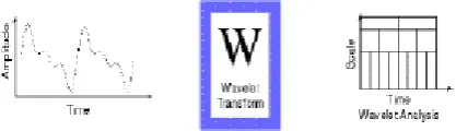
[image:5.595.74.283.499.559.2]----(4.2) A wavelet is a little wave which has its vitality packed so as to give an apparatus for the investigation of transient, non-stationary or time shifting wonders. It is an amazing asset to remove data from the present flag at the same time in both time and recurrence space.
Fig 6: Wavelet transform of a time series signal. IV. ARTIFICIAL NEURAL NETWORK
The counterfeit neural system is a system of interconnected components. When all is said in done the capacity of neural system is to create a yield design with an information design. Neural systems can gain as a matter of fact and will give a yield of in any event a best speculation of deficiency type under any conditions.
The architecture of a multi-layered feed forward neural system includes an information layer; One yield layer and at least one hidden layer. All layers are fully fused and feed forward sorted. Yields are non-capacity of information sources, and are constrained by the weights registered during the learning process. The learning process used is regulated and the worldview of learning is diffusion back. For the BP preparation process, a finite resolution capability is required and the resulting sigmoid is used.
The way to blame diffusion system learning is the ability to change its synaptic load in light of mistakes. Figure 7 shows the class outline of this learning (ie) posterior propagation calculation.
Fig 7: Block diagram of supervised learning of ANN
The MLFNN is generally prepared in an administered way with an exceptionally mainstream calculation known as blunder back engendering calculation. Data about mistakes are additionally separated back through the framework and used to change associations between layers, thus improving exposition. The blunder back attaching process involves two through different layers of the system, in particular: forward pass and reverse. go. In further pass, an initiation instance is connected to the tangible hub of the system, and its effect is transmitted through layer by layer systems. At last a lot of yields is delivered as the genuine reaction of the system .The real reaction of the system is subtracted from an ideal reaction to create blunder signal. This mistake sign is then engendered in reverse through the system against the heading of the synaptic associations .The synaptic loads are balanced in order to make the genuine reaction of the system a lot nearer to the ideal reaction.
VI. PROPOSED SCHEME
The proposed calculation for arranging transient wonders in power transformers joins wavelet change and neural system. The wavelet change is connected to differential current sign, for extricating a few highlights. Neural system is utilized for recognizing interior shortcoming from other working states of the power transformer. The stream diagram of the proposed calculation is appeared in Figure 8 and it very well may be clarified as pursues:
The differential current sign are acquired from power transformer displaying in Simulink condition with different working conditions (Normal, Inrush current, Over excitation, CT immersion and Internal deficiency)
Then wavelet change is connected to deteriorate the differential current sign into a progression of wavelet coefficients (both estimation and point by point coefficients).
ANN engineering is worked to separate the shortcoming condition from other working conditions.
Two diverse ANN Architectures have been planned and created.
Artificial Intelligence Based Discrimination of Transformer Inrush and External Fault Currents
demonstrate inward issue condition.
The yield got from ANN is remade back to get the first yield, which is utilized to show whether the given transient is an interior issue or some other working conditions.
6.1 Decomposition of recreated differential current sign utilizing wavelet changes:
The present sign are gotten from recreating the circuit for various breaker shutting timings like 3.25/60,5.25/60 and so on. These sign are then disintegrated into wavelet coefficients that are sustained as info factors to neural systems. For deterioration there are numerous sorts of mother wavelets, for example, Harr, Daubichies, Coiflet and Symmlet wavelets. One of the mother wavelet appropriate for identifying low plentifulness, brief term, quick rotting and high recurrence current sign is Daubichies Wavelet. . Consequently in this proposed work Daubichies wavelet is utilized. There are numerous kinds of wavelet channels from (DB2 to DB44) in Daubichies wavelet family for wavelet decay process. Channels and goals levels for wavelet deterioration and reproduction stages are to be chosen in such a way, that they can counterbalance the impact of associating and they can replicate a similar sign after recreation. In this work DB2 channel at level 5 is picked for disintegration process since this kind of channel recreates a similar unique sign after remaking.
By direct convolution hypothesis, for a solitary deterioration (goals) the quantity of channel coefficients created by DB2 channel is 4 that are 1 estimation coefficient and 3 itemized coefficients. This estimate coefficient that is low recurrence segment are additionally deteriorated into Approximation and point by point coefficients (An and D). Accordingly for "n" number of goals, there will be "n" number of nitty gritty coefficients, just a single estimation coefficient. At every breaker time the sign is disintegrated and the standard deviation of the itemized coefficient at level 1 is taken. This procedure is proceeded for various breaker timings. These standard deviations are utilized to prepare the neural system, with the goal that it should separate outside shortcoming from Inrush current.
6.2 Data for ANN engineering preparation and testing: The system is designed to recognize two types of signals (entrails, external defects). The rated intensity transformer selected for entertainment is 31.5MVA 110 / 11KV. Inrush flow and L-G problem, power transformers such as L-L reduction and 3-at faults are obtained using MATLAB / SIMULINK flowing out at different breaker times. In view of breaking these signals using DB2 at level 5, the standard deviation of the point by point coefficient at level 1 (D1) is given as a contribution to the preparation of the nervous system. Ten specific breakers are timed for which reproduction is performed. A standard deviation coefficient is acquired for each step for different times of the breaker. There are 10 standard deviation coefficients for each step for all ten breaker times. There are exactly 30 standard deviation coefficients. Similarly, 30 standard deviation coefficients are accessible for each of the outliers.
[image:6.595.314.548.316.494.2]These standard deviation information, which is accessible by the disintegration of the use of waves contributing to formulate the nervous system, is used. ANN engineering yields two shortages, which is '0' for the inrush current and '1' for the external reduction.
Fig 8: Algorithm of the proposed scheme
6.3 Circuit Operation:
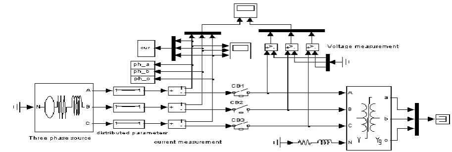
6.3.1 Inrush Current Analysis Circuit:
[image:6.595.97.554.554.707.2]All the three circuit breakers are shut at similar moments with the goal that Inrush current moves through the transformer. To have distinctive inrush current extents the circuit breakers are worked at various exchanging timings. The circuit breakers are shut for ten distinctive exchanging timings (i.e.) 3/60, 5/60, 7/60, 9/60, 11/60, 13/60, 15/60, 17/60, 19/60, 21/60. To acquire Inrush current all the three circuit breakers are worked at a similar moment at every one of the above breaker timings.
For the exchanging timing 3/60, the all the three circuit breakers are shut at the moment of 3/60. The vitality source is currently associated with the power transformer through CB's. From the present estimation, Flow through all three lines is tapped for the MATLAB workspace. The information in the workspace is skewed and the approval coefficient using the expansion coefficient and the wavelet
tool stash (>> help wavemenu). The decomposition is terminated using four diverse mother wavelets i.e. Daubichies wavelet (db 2), Haar wavelet (haar), Symlet wavelet (sym 2), Coiflet wavelet (coif 2). Decay is done at level 5.The standard deviation of the point by the point coefficient (D1) at level 1 is taken for the given exchange time for all three phases. Circuit breakers are for example worked for a new exchanging timing of 5/60 and a similar method is remodeled for new exchanging timing. This system is carried forward for all exchanging timings. The date of this standard deviation is given as a contribution to the ANN program for further investigation.
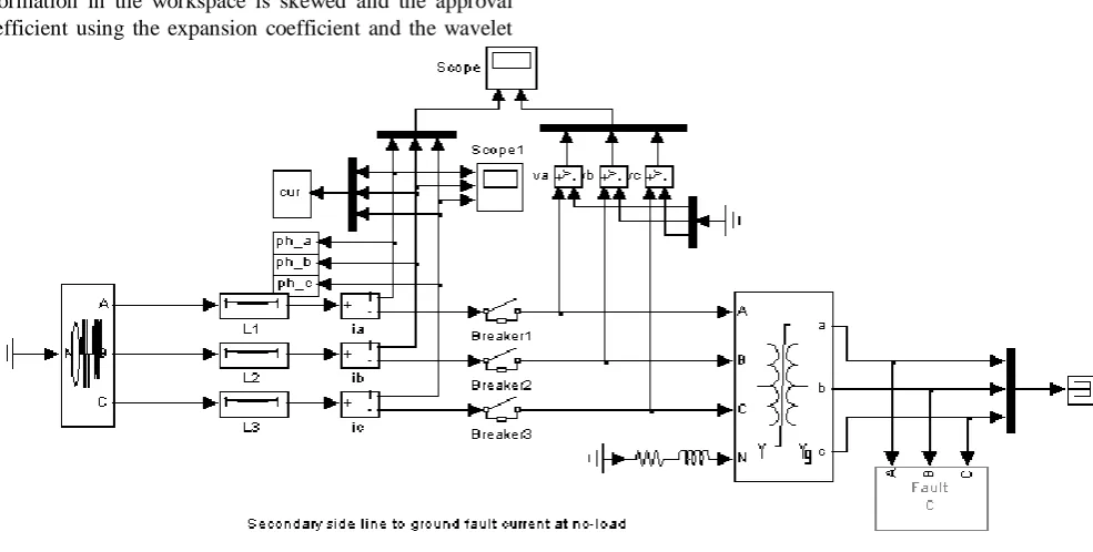
[image:7.595.59.552.225.474.2]6.3.2 L-G Fault:
Fig 10: L-G Fault Current Analysis
All three circuit breakers do not close at the same moment, rather they are closed when the individual voltage waves are taking their greatest impetus to limit the shock effect. The end time of CB is given below. The L-G defect is associated with 25/60 cycles to 30/60 cycles for example 5 cycles. CBs are closed at their first exchanging time as given below. These exchanging timing are pursued for the various issue figurings for example L-L deficiency, 3-Φ issue For the main exchanging timing3.The 25/60 (phase A) life power source is currently connected to the power transformer via CB. There is currently an L-G deficiency associated with phase one. By current estimation, the flow through all three lines is tapped at the MATLAB work space. Information in the workspace is skewed for expansion coefficients and estimation coefficients using the Wavelet Tool Kit (>> Help WaveMenu). The decay is terminated by using four distinct mother wavelets i.e. Daubichies wavelet (db 2), Haar wavelet (haar), Symlet wavelet (sym 2), Coiflet wavelet (coif 2). The fall is done at level 5. The standard deviation of the Knight Gritti coefficient (D1) at level 1 is taken for the given exchange time for all three phases. Circuit breakers for example 5.25 /
Artificial Intelligence Based Discrimination of Transformer Inrush and External Fault Currents
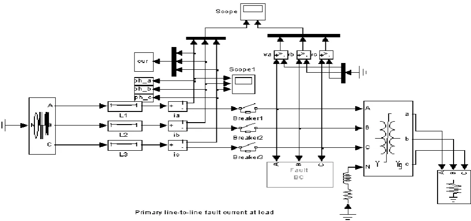
[image:8.595.70.556.63.291.2]6.3.3 L-L Fault:
Fig 11: L-L fault current analysis
All three circuit breakers do not close at an equal moment, but rather when the individual voltage waves are taking their most extreme impetus to limit the shock effect. L-L deficiency is associated with 25/60 cycles for 5 cycles to 30/60 cycles. CBs are closed at their first exchanging time. The vitality source for the primary exchange time 3.25 / 60 (Stage A) is currently connected to the power transformer via CB. Currently an L-L issue is connected between stages A and B. By current estimation, the flow through all three lines is tapped for the MATLAB workspace. The information in the workspace is decomposed by the expansion coefficient and the approval coefficient using the fragmentation tool waveform (>> help wavemen). The decomposition is terminated using four diverse mother wavelets i.e. Daubichies wavelet (db 2), Haar wavelet (haar), Symlet wavelet (sym 2), Coiflet
wavelet (coif 2). The fall is done at level 5. The standard deviation of the point by the point coefficient (D1) at level 1 is taken for the given exchange time for all three phases.Circuit breakers are worked for example 5.25 / 60 for new exchanging timing and similar functionality is remodeled for new exchange timing. This technique is carried forward for all exchanging timings. The date of this standard deviation is given as a contribution to the ANN program for further investigation.
Additionally the L-L deficiency is connected between Phase B and C and Phase An and C exclusively and a similar technique is completed for all the distinctive exchanging timings.
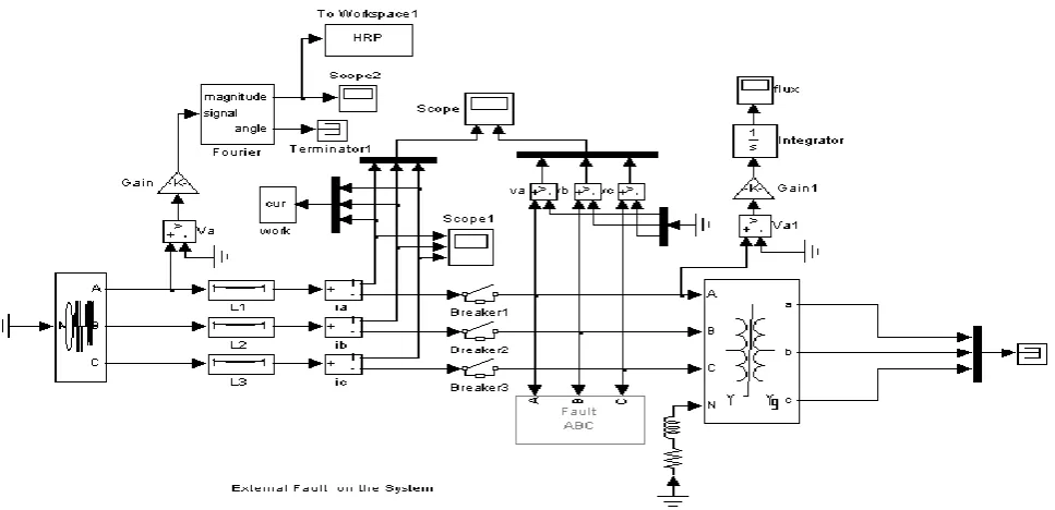
6.3.4 3- Φ Fault:
[image:8.595.61.563.505.718.2]All three circuit breakers do not close at an equal moment, but rather when the individual voltage waves are taking their most extreme impetus to limit the shock effect. The 3–3 digit is associated with 25 cycles for 25/60 cycles to 30/60 cycles for example 5 cycles. CBs are closed at their first exchanging time. The vitality source for the primary exchange time 3.25 / 60 (Stage A) is currently connected to the power transformer via CB. Currently 3-a deficiency is associated. Information in the workspace is skewed for expansion coefficients and estimation coefficients using the Wavelet Tool Kit (>> Help WaveMenu). The decay is
terminated by using four distinct mother wavelets i.e. Daubichies wavelet (db 2), Haar wavelet (haar), Symlet wavelet (sym 2), Coiflet wavelet (coif 2). Decay is done at level 5.Circuit breakers for example 5.25 / 60 are worked on for new exchanging timing and a similar method is restarted for new exchanging timing. The date of this standard deviation is given as a contribution to the ANN program for further examination.
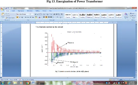
[image:9.595.66.556.189.392.2]VII. SIMULATION RESULTS
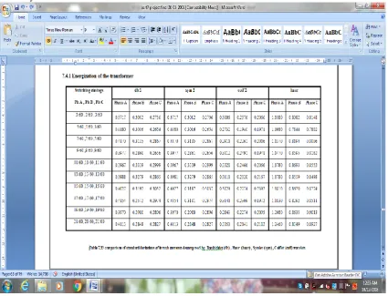
Fig 13. Energization of Power Transformer
[image:9.595.57.511.415.694.2]Artificial Intelligence Based Discrimination of Transformer Inrush and External Fault Currents
[image:10.595.70.554.70.304.2]Fig 15: External Faults on the Transformer
Fig 16: Waveforms for L-G Fault(Fault on Phase-A)
Fig 18: Waveforms for 3- Φ Fault
Energization of the Transformer for Different Switching Times of all the three phases at different angles are carried out.
Different Wavelet Transforms are applied for all possible switching conditions and various fault conditions.
Daubichies Wavelet,Sym Wavelet, Coif Wavelet and basic haar wavelet are applied at different levels until maximum accuracy level is reached. Information in the
workspace is skewed for expansion coefficients and estimation coefficients using the Wavelet Tool Kit (>> Help WaveMenu). This strategy is carried forward for all exchanging timings and the standard deviation information obtained is given for further examination and classification of transformer currents and various external faults on the transformer as a contribution to the ANN program.
[image:11.595.91.517.396.721.2]Artificial Intelligence Based Discrimination of Transformer Inrush and External Fault Currents
Table2: Comparison of standard deviations of Fault current (L-G fault) (Ph A) decomposed by Daubichies (db) , Haar (haar) , Symlet (sym) , Coiflet (coif) wavelets.
[image:12.595.59.551.73.399.2]Table 4: Comparison of standard deviations of Fault current (L-G fault) (Ph C) decomposed by Daubichies (db) , Haar (haar) , Symlet (sym) , Coiflet (coif) wavelets.
[image:13.595.65.545.382.748.2]Artificial Intelligence Based Discrimination of Transformer Inrush and External Fault Currents
Table 6: Comparison of standard deviations of Fault current (L-L fault) (Ph B & C) decomposed by Daubichies (db) , Haar (haar) , Symlet (sym) , Coiflet (coif) wavelets
[image:14.595.60.550.426.713.2]Table 8: Comparison of standard deviations of Fault current (3 – Φ fault) decomposed by Daubichies (db) , Haar (haar) , Symlet (sym) , Coiflet (coif) wavelet.
[image:15.595.63.516.47.734.2]Fig 19: ANN Training Output for Fault Current Analysis
Fig 20: ANN Training Output for Inrush Current Analysis
VIII. CONCLUSION
The circuit in the proposed strategy uses wave transforms along the nervous system to isolate the inrush current and
the out-of-point current flows into a power transformer. The current waveform decomposition is done with four different wavelets for Coiflet wavelet, Daubichies wavelet, Symlet wavelet and Haar wavelet. The reproduction results acquired demonstrates that the proposed calculation precisely gives high working affectability to inside flaws and stays stable for other working states of the power transformer. The consolidated WNN gives progressively exact outcomes and it has rapid reaction and expanded capacity to segregate even low-level deficiency signals from other working conditions. The proposed technique demonstrates to be productive strategy for segregating transformer flows.
.
IX. REFERENCES
1. T. Shanti, A.S. "IEJJ Trans04 03 PP1105-1115
2. Myong-Chul Shin, Member, IEEE, Chul-won Park, and Jong-hyung Kim, "Fuzzy logic-based relays for large power transformer protection" IEEE Trans.Power Del, Vol.18, No.3, July 0.2003
3. X.Lin, J.Huang, L.Zeng and Z.Q. Bo, "Analysis of electromagnetic transient and moderation based on second protection of second HHHH power transformer," IEEE Trans. Power Del., Vol.25, No. 4, pp. 2299–2307, Oct.2010..
[image:15.595.61.307.392.736.2]Artificial Intelligence Based Discrimination of Transformer Inrush and External Fault Currents
5. Monseff, H., and Lotiford, S.. "Internal fault current detection based on wavelet changes in power transformers," Electric Power Systems Research, Vol. 77 pp. 1637–1645, 2007.
6. Morvez, Z., Vishwakarma, D.N., and Singh, S.P. "ANN-based protection scheme for power transformers," Electric Machines and Power Systems, vol.28, No.9, pp.875- 884, 2000.
7. Bastard, P., Munier, M., and Regal, H.. "Neural Network-Based Algorithms for Power Transformer Differential Relays," Proceeding Industrial Electric Engineering, Volume 162, Number 4, pp. 3-7- 342,. 1995.
8. J. Ma., Z. Wang, q. Yang, and Y. Liu, "Identification of transformer pressure based on generalized grille curve," IEEE Transactions on Power Distribution, Vol. 26, no. 2, pp. 588– 595, 2011.
9. Segatto, E. C., and Corey, D. V. "A differential relay using power transformer for intelligent tools," IEE Transactions on Power Delivery, vol. 21, no. 3, August 2006.
10. Morvez, Z., Vishwakarma, D. N., and Singh, S. P. Radial basis function (RBF) neural network for protection of "Power Transformers and Systems, Vol." 29, pp. 307– 320, 2001.