Abstract: There has been a lot of research in the field of fingerprint extraction techniques due to its growing importance in area of criminology and advance science to achieve the high security feature associated with its unique quality of identification. Studies have been made so far for various applicability of finger recognition which involves recording and matching of stored images with high estimation of correctness using the ridge and minutiae based pattern flowBut the major challenge for finger print matching and its identification lies with the emergence and extraction of clear recognizable images from the latent unidentifiable pattern on an object. This paper focuses on latent image processing patterns and indexing methodologies with ridge and minutiae based orientation techniques .Using the SVM model with algorithms this proposal will not only compute the direction of minutiae but also its singular point rotational direction thus an efficient algorithm is the aim of this paper which will further use binary decision making and pre-processing state of the art technique and also discuss the post-processing steps.
Index Terms: Binarization , Equalization,gradient,magnitude minutia,ridge`
I. INTRODUCTION
Fingerprint of -lately has become a topic of considerable importance its extraction and identification has been crucial to identify suspects . Many developments has been taking place every year owing to its increase multi-functionality using indexing method but still a large area with regards to extracting fingerprints and its various methodologies restrict and remain on research papers only and are not applied in practical to the fullest. Ideally the real problem is indexing of the latent unidentifiable images. Images which are excessively blur and unclear here ,we would discuss the most primary form of investigation its applicability and its pre processing and the post processing system
But before commencing for the pre-processing stages it is necessary to understand ridges and valley in brief.
Ridges and valley [1]form the main component of the fingerprint indexing. They both flow in a local constant direction where in ridge has further following features such as Ridge bifurcation, ridge endings, short ridges and crossover ridges[2]. By using these various clues mentioned above the fingerprint examiner is able to correctly identify the minutiae but for this ridge and furrow structures should be in a non corrupted form.
Revised Manuscript Received on June 05, 2019
Harivans Pratap Singh, Research Scholar, Uttarakhand Technical University, Dehradun, Assistant Professor, ABES Engineering College Ghaziabad (Uttar Pradesh), India.
Priti Dimri, Department of Computer Science and Applications, G.B. Pant Engineering College, Ghurdauri, Uttarakhand, India
Prof. Shailesh Tiwari, Department of Computer Science and
Engineering, ABES Engineering College, Ghaziabad, India.
Valleys are represented by the white area between the ridges and also ridge ending can be viewed as the bifurcation of the valley portion and that bifurcation can be identified as the end of the valley.These ridges and valleys are separated by minutiae points are the abnormal points or called the irregular points [1] seen between the regular or constant patterns of a fingerprintnow coming back to the pre-processing stages which is shown in below Fig 1.
.
II. METHODOLOGY
Histogram Equalization is the transfer of gray levels and graphical representation of the intensity distribution of an image so that the image formulation histogram is equalized to a constant and is mostly used contrast enhancement as you can see in the image that the pixels [3]seem to form groups and gather around the centre of the available range of majorities here histogram equalization stretches out the range.[4]
An Approach To Latent Fingerprint Indexing
Preprocessing Techniques and Its Functionality
Harivans Pratap Singh, Priti Dimri
,
Shailesh Tiwari
Histogram Equalization
Binarization Upload Your Image
Image Segmentation
False Minutiae Removal
ROI Extraction,Thinned ridge map,removal of H breaksand spike
Block Direction Extraction & Adaptive Binarization after FFT
Alignment & Matching Stage
Fig.2.Image of a fingerpint and its histogram Equalisation
The process of Equalisation involves mapping one distribution to another where the programs loads and image convert the original image into gray scale equalize the histogram and display the source and equalized images in a window.[5] Then it is followed with image enhancement where the image which is uploaded having poor quality which can be upgraded by enhancing the image and thus the contrast between the ridges and the valleys can be increased[6] after which edge detection takes place where points on the picture the most important information works and the gray scale values changes between pixels joining the false scattered dots of ridges due to inadequate ink connectivity[7]
Fig.2 Enhancement by FFT
As visible in the figure above, the image is being divided into small processing pixels rather say blocks called the Fourier transform. .[8]Tobrighten a particular block by its most dominant frequencies ,the FFT of the block and its magnitude is multiplied by set of times as a result the parallel ridges gets evenly separated and turn into thick ridges. This enhanced image after improvements is made by FFT ,[9]connects the scarce looking points which are marked by slightly broken false points on ridges which forms connections between ridges by overlapping blocks of the same size.
Thus a connection is formed from the broken ridges reconnecting a set of pixels from a small region and if the FFT of a block is chosen which contain more than one
parallel ridges then the ridges are formed from the dominant frequencies of the block.[10]
As it is possible to multiply the FFT of a block number of times which will make the parallel ridges thick and finely separated also if the magnitude of the FFT was sqared or cubed the outcome is much better but the the minutia gets obscured. Thus the below formulae is used for rather than multiplying whole factors of FFT.[11]
Where g(x,y) is the enhanced block and ‘k’ is a constant determined experimentally, which is between 1 and 3[12] After rounds of experiment it was observed that values of k between 1.4 to 2.3 yield the best output. The above formulae summarizes the overall process.[13]
Fig.3. Showing Adaptive Binarization after FFT Fig.3
(1)Adaptive binarization.:The presence of background noise and disturbing textures are major factors which affect the recognition quality.[14] Brightness, poor contrast ,low recognition quality adds to the brightness of the background and the filtering of the black areas along the ridge of each separate minutia is measured to get a clear pattern. The size of local area is calculated first and each local area are rescaled to the same size ie.0.255 pixel wise window is moved throughout the fingerprints and the coordinates are extracted from each amplitude spectrum. The ideal peak is calculated and the height is located.[15]The ration between the height of the ideal peak and the height of the located peak is calculated as
R=
(16)
Now, decision is made whether or not further examination is required in the form of expansion in an out of the local area. After all the coordinates have been extracted the polar is formed by combing the mean value and a median filtering (2) Block direction image :
Based in the dominant ridge direction(DRD)[17] images are first standardized to have
enhance the images from set of filters using DRD.
=
[18]
[image:3.595.320.535.102.339.2]In this model Gx and Gy are the gradient magnitudes masks outcome of 3x3 quadrants. To get the correct .The numerator and the denominator value is being analysed ie., If the value of numerator is positive and value of the denominator is negative 180degree is added to and if the denominator results to negative 90 degree is added to otherwise remains unchanged .The obtained DRDs are than revised and given volume to one of 16 possible directions 0-180 degree.The DRDs are used to form the block direction image .Now the delta and core points are detected from DRD points.The DRD which are rapidly changed are smoothed with algorithm maintains the fast changes near core and delta points.[19]
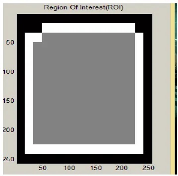
Fig.4. ROI Extraction
It is a that part of an image that you want to select to form few operation or performing filtering.ROI can be created of many shapes. Through ROI[20] a binary mask image is being created. ROI’s are groups of accumulated pixels but you can also state ROI’s by intensity values .Below are the steps involved:-
1. First segregate by allocating a mask and separate ROI from the background then apply filter to ROI.
2. Creation of binary mask classified pixels on belonging to the region of interest or the background
3. Sharping ROI in an image by mask filtering. 4. Defining of own mask and filter to ROI
5.By interpolating inward the pixels are being replaced in the region.[21]
Figure 5 shows thinned ridge map and the curve of the finger Thinning of the ridge eliminates the pixels from further creating noise till the ridges reaches to a certain width in each scan pixels are being marked on a window of 3x3 on the basis of redundancy and after several scans the spotted pixels are marked and removed. This method traces besides the ridges having largest gray intensity value since binarization implicitly stresses on maximum gray scale intensity value it has far more computational complexities.
Fig.5.Thinned ridge Mapping
[image:3.595.81.261.292.470.2]The thinned image is further penetrated inorder to remove the H[22] breaks as seen in the Fig.6.these points which form H points are most noisy and are thus removed on the contrary if left unattended it will give formation of wrong minutia.
Fig.6. Remove H breaks
[image:3.595.316.540.410.624.2]Fig.7. removal of spike
Fig.8. False Minutia Removal:-
Inadequate amount of ink intertwined connections of ridge and because of excess ink false ridge takes place. To remove false minutia from the well segmented minutiae of a fingerprint image, we would here understand and apply the fuzzy rule, [23]where rule of ‘IF A THEN B’ is applied. Points pertaining to minutia and are close to the boundary under 10 pixels are out looked and avoided for extracting false minutia which are obtained from the edge of the fingerprint undergone the thinning process.Below is the fuzzy rules extracted ………….[24]
Fig.8. Real minutia after removing false minutia points
Rule 1:IF the distance between termination and bifurcation is less than D.
Then remove both the minutiae.
Rule 2 : IF the distance between two bifurcations is less than D,
Then remove both the minutiae.
Rule 3: IF the distance between two terminations is less than D.
Then remove both the minutiae.[25]
The average inter ridge distance (D) between two neighbouring ridges which is calculated by the formulae
[26]
The distance between two neighboring ridges and its average the average of inner ridge refers to one another. The value of D is derived by scanning row as well as column by summing up all pixels whose value is one and scan of row of the thinned ridge image further diving it with above summation to get an inter ridge width. This type if scans are performed on multiple row and column. At last all the inter-ridge widths are averaged to get the D. Numerous results have shown that the result is never more than D also fingerprints images which are processed are always close to 6 pixel thus empirically to make the process easier the value of D is set to 6.
Fig.9. Matching & alignment through orientation field
After removal of false minutia points and extracting related real minutia points, minutia matching is done to analyse and check whether it belongs to the same fingerprint set or not. Thus here the ridge orientation flow direction is being used to identify the flow between the ridges.
Minutia matching with a score
Minutia Alignment is done by choosing minutia from every set to find ridge correlation factor comparatively between them. Thus the point obtained is further sampled per ridge length initiating from the minutia point similarity is recorded by correlation between two points derived from :-
[27]
Here (xi..xn) and (xi..xn) are the pairs of x coordinates for each of the two minutia chosen. And m is least one of the n and N value. If thesimilarity score is larger than 0.8, then step 2 is considered, otherwise continue to match the other pair of ridges. After that each set of minutia is transformed to match the unified x-y coordinate .Thus a fresh coordinate system is formed to the same direction of the minutia.
[28] The above algorithm is being used to derive an elastic string to search the sets of matching
algorithm minutia mi in I2’ and a minutia mj in I2’ are
considered "matching,". The sd called the spatial distance between comparing them is smaller than a given tolerance r0and the directional difference denoted by dd between them
is smaller than any angular tolerance .[29]
Let mm be an indicator function that returns 1 in the case where the minutiae mi and mj match according to above equations.
[30]
Now the total number of matched minutiae pair given by, num (matched minutiae) = ∑ mm (mi,mj)
and final match score is given by,
[31]
III.
EVALUATION:
The performance evaluation is done for the entire recognition system FRR and FAR is being measured were FRR being False rejection rate and FAR being False Acceptance Rate, the FRR for image is computed by matchingeach sample with remaining samples of the same finger from the image that of database whereas FAR is computed by matching the first samples of each finger in the database with the first sample of the remaining fingers to compute the false acceptance rate . Experiments performed by researchers suggest that FAR and FRR values were around 35% arriving to a verification rate of algorithm to reach at 65-70%. Also ERR is calculated which denotes Equal error rate where the common value of the FAR and FRR is computed using the least value assigned at a point showing FAR equal to FRR.
POST PROCESSING STAGE:
The post processing stage aims at minimising the false minutia and to increase the efficiency with increased probability of fingerprint matching this stage may detect false minutia generated by factors such as noisy images created by thinning process it eliminates spurious minutia and ridge ending point which is connected to a bifurcation point below a certain threshold distance is eliminated Also a boundary effect treatment is applied in which the minutia below a certain distance from the boundary of the foreground region are deleted. A contrast stretching is primarily made so that image is enhanced by overall contrast. Hence the obtained image is further binarized before giving any input to the FFT technique.[32]
IV. PROPOSEDWORKUSINGTHE SVMMODEL:
While working on fingerprint extraction pre-processing stages there are lot of challenge faced one such problem isthat of rotation of the fingerprint image .Every time when a finger print extracted it is not possible to extract in the same orientation as that of the source fingerprint hence the unidentified requirement lies under different angles can be obtained from the SVM model where the SVM classifier with the PST rotation can improve the results of recognition system.
4.1 SVM ALGORITHM
Here a collection of SVM set is formed out of the stated algorithm which initializes with the closest pair of points from the contradicting classes in a Direct SVM algorithm. The violating points forms the base of the detection from the list of the candidate set. It may be so occur that the addition of such violating points marked as a support vector may restrict other candidates support vectors which are already forming a part of the set. Therefore such points are simplified from the database until no violations are found.Quadratic penalty formulation to ensure linear arability in the kernel space[33] out of the data points will be used.
4.1 (a) Finding the nearest set of points:
After observing the closest pair of points in the kernel space computations is done using the kernel space n2 that
represents total number of data points, hence the nearest point in the feature space are similar to that of the immediate neighbour unlike the exponential kernel
(b) Addition of a point in the Support vector set:
Considering a set S containing only support vector from the below equation the gi is computed which is a changed gi and adds to the other support vector .
[34] Here ∆αi is the change in the value of αi and ∆b is the change in the value of b. We start off with αc = 0 and update αc as we go along.
The train set forming pair of sets extracted s1 ,s2, s3 & Sm separately are trained to form sets of G1 ,G2 where they are being formed as the collection of classifiers whose results are combined outputs also parallel forming the test sets which are further done by series of prediction.
The Predicted sets of group are further processed by PHT ie. Polar Harmonic Transform that are known to generate rotational invariant features .By using PHT there is minimal vulnerability issue ,They are basic waves harmonic in nature where at the very end of each pixel values are multiplied and added to obtain the final kernel value.
Filter is being applied and watershed is done to enhance the image followed by cropping up the image in a circular direction feature extraction algorithm is done to form the train set feature for SVM classifier , [35]testing images is being taken and extracted from the data set. Repetition for multiple images at multiple angles is performed which computes the parameter of FAR and FRR for accuracy testing,
V. CONCLUSIONANDFUTUREWORK:
The objective of the research paper is to show the result of each stage using the various pre-processing enhancement techniques and assess the feasibility of every step to improve understanding of various latent fingerprint extraction and enhancement techniques. We have presented a framework for combination of the
improves and reduces the False Acceptance Ratio and False rejection ratio. There has been major improvement in the overall performance of fingerprint classification and verification.
Our further work will include improvements to the SVM algorithm because though in the proposed SVM model overall performance as been increased but the training time has increased comparatively hence an efficient SVM algorithm to solve this problem efficiently will be our aim.
REFERNCES:
1. Paramvir Singh,Dr. Lakhwinder Kaur,2015Fingerprint Feature extraction using ridge and valleys,IJERT,Patiala,India.
2. Saparudin,Ghazali Sulong,2016,A Technique to improve ridge flows of fingerprint orientation fields estimation,telkomnika,Malaysia 3. J.Alex Stark ,2000,Adaptive Image Contrast Enhancement using
generalisations of histogram equalisation, IEEE ,Cambridge,UK. 4. Virendra P. Vishwakarma,Sujata Pandey, M.N gupta,2009,Adaptive
histogram equalisation and logarithm transform with rescaled low frequency DCT Coefficeinets for illumination normalisation,IJORTIE,delhi,India
5. Wu Zhihong,Xiao Xiaohong,Study on histogram Equalisation,2011,IEEE,China
6. Omprakash Patel,Yogendra P.S Maravi,Sanjeev Sharma,2013,A comparative study of histogram equalisation based image enhancement techniques for brightness preservation and contrast enhancement,SIPIJ,Bhopal,Madhya Pradesh, India.
7. alka rani, palvee, deepak sharma 2014 , svm based classification and improvement of fingerprint verification, ijsetr,india
8. R Dorothy,Joany RM,Joseph Rathish,S Santhana Prabha,Image enhancement by histogram equalisation,2015,IJNCSEDindigul,India. 9. Sonal Raj,Sawat raj,Sanjay kumar,An improved histogram equalisation
technique for image contrast enhancement,2015,ICC,Karnataka,India. 10.Lin Hong,Yifei Wan ,Anil Jain,Fingerprint Image
Enhancement:Algorithm and Performance Evaluation,Michigan 11.Sangram bana, Dr.Davinder KAur,2012,Fingerprint Recognition using
Image Segmentation IJAEST,INDIA
12.S.Neethu, S Sreelakshmi, Deepa Sankar,2015, Enhancement of Fingerprint Using FFT×|FFT|n Filter,Elsevier,Kochi.
13.Kasaei, S, Deriche, M, Boashash, B,1997,Fingerprint feature extraction using block-direction on reconstructed images,IEEE regional annual conference,Newyork
14.M. James Stephen,P. V. G. D. PrasadReddy,Vadlamani Kartheek ,Ch. SureshSuresh Chandra Satapathy,2012, Removal of False Minutiae with Fuzzy Rules from the Extracted Minutiae of Fingerprint Image, Springer,India
15.M. James Stephen, Prof. Prasad Reddy P.V.G.D, Prof.
K.R.Sudha,2013, Removal of False Minutiae with Modified Fuzzy Rules,IFRSA,INDIA
16.Can Eyupoglu,Implementation of Bernsens’s locally adaptive binarization method for gray scale images,2017,TOJOSAT,Istanbul,Turkey
17.Nalini K Ratha, Shaoyun Chen,anil K Jain,1995,Adaptive flow orientatin nased feature extraction in fingerprint images.contract from the institute of Defense Anayses,Michigan.
18.S.Kasaei, M Deriche, B Boashash,1997,Fingerprint feature extraction using block direction on reconstructed images, IEEE, Brisbane, Australia
19.L.Zhang,2014,Extraction of direction features in fingerprint image applied mechanics and materials, Applied Mechanics and materials,China.
20.Bazen A.M., Gerez S.H,2002,Systematic methods for the computation of the directional fields and singular points of fingerprints ,IEEE,Enschede,Netherlands.
21.21Hiroki Hayashi,Fumihiko Saitoh,2005,Roation invariant image matching by interpolated eight direction block matching,EEJ,Japan 22.22PArul Mishra,Ajit Kumar Shrivastava,Amit Saxena,2013,Enhanced
thimning based finger print recognition ,IJCI,M.P, Inida.
23.Shadrokh Samavi,Farshad Kheiri,Nader Karimi,2005,Binarization and thinning of fingerprint images by pipelining,MVIP,Iran
24.Romulo Ferrer L.Carneiro, Jessyca Almeida Bessa, Edson Cavalcanti Neto,Auzuir ripardo de Alexandria,Techniques of Binarization,Thinning and Feature Extraction applied to a fingerprint system,IJOCA.
25.S. Mousmi,Dr.T Meysppan,,2013,Fingerprint identification using minutiae matching,IJETT,Karnataka,India.
26. Usha Rani,2016,Fingerprint Image Enhancement based on various techniques, features, extraction and matching ,IRJET, Haryana,India. 27. Xiping Luo,Jie Tian and Yan Wu,2009,A minutia matching Algorithm
in fingerprint verification,IEEE,Bejing,China.
28. Xudong Jiang,Wei-Yun Yau, 2000,Fingerprint minutiae matching based on the local and global structures,IEEE ,Singapore.
29. Yuliang He,Jie Tian,Xiping Luo .Tanghui Zhang,2002,Image enhancement and minutiae matching in fingerprint verification,Elsevier,Beijing,China.
30. Lukasz Wieclaw,2009. A minutiae based matching algorithms in fingerprint recognition systems,JOMIT,Sosnoweic,Poland.
31. Ravi J,K B. Raja,Venugopal K.R.,2009,Fingerpritn recognition using minutia score matching,IJOESAT,Bangalore,India.
32. M Usman Akram,Anam Tariq,Shoaib Ahmed Khan,Sarwat Nasir,20018,Fingerprint image Pre-and Post processing ,IJOB ,Rawalpindi Pakistan.
33. Alka Rani,Palvee,Deepak Sharma,2014,SVM based classification and improvement of fingerprint verification,IJSETR,India.
34. S Adebayo Daramola,Tola Sokumbi and A.U. Adoghe,2013,Fingerprint Verification system using support vector machine,IJCSE,Nigeria.
35. Chi-Jim Chen,Tun Wen PAi and Mox Cheng ,2015, A support Vector Machine approach for truncated fingerprint image detection from sweeping fingerprint sensors,MDPI,Taiwan
PROFILE
Harivans Pratap Singh has received his M tech degree
from Uttrakhand Technical University Deharadun ,India and currently pursuing his PhD. From UTU and is working as an Assistant Professor in Computer Science and Engineering Department of ABES Engineering College Ghaziabad India .His research work includes Latent finger print indexing their segmentation and identification efficiency. Other area of interest are Software Engineering,Software Testing(Manual & Automation), UML on UMLet Design Patterns,and having 6 yrs of work experience in IT industry
Dr. Priti Dimri has received her PhD from
Uttrakhand Technical University and is currently working as an associate prof. at G.B.PANT Institute of Engineering and Technology, Ghurdauri, Pauri India her area of specialization is IT service Management and has done her research work in field of computer science fractals(Computer Graphics), has published her various research work in national and international journals, She is the author of “A study of Chaos, Fractals and their applications using fixed point “.She is a member of ISTE membership,
Prof. Shailesh Tiwari has received her PhD from