International Journal of Innovative Technology and Exploring Engineering (IJITEE) ISSN: 2278-3075,Volume-8 Issue-12, October 2019
Abstract: This paper analyzes the Digital Pre-Distortion linearization technique using a low-precision Analog-to-Digital Converter (ADC). The output of a power amplifier exhibits various spurious emissions, spectral regrowth and intermodulation distortion (IMD) products due to its non-linear behavior. So, to preserve the performance of power amplifier, linearization becomes mandatory. Digital Pre-Distortion does the training on the output of the power amplifier (distorted signal) and generates exactly the inverse characteristics to that of power amplifier. Their cascading results into a linear response. In practical systems, the output of power amplifier has to go through an analog-to-digital converter for digital processing and a low-resolution ADC results in the degradation of the signal and affects the DPD performance. But a low-resolution ADC not only reduces the computational complexity in the digital processing but it also provides lower power consumption and costs less because less hardware would be required. In this work, the aim is to find the precision up to which ADC resolution can be reduced without affecting the DPD performance in a significant manner. This paper evaluates the performance of two DPD systems - Full-band DPD and Sub-band DPD and from simulations, it is observed that for a full-band DPD, 1-bit ADC can be reliably used and for a sub-band DPD, single bit to 4-bits ADC can be used.
Keywords: Power Amplifier, Digital Pre-Distortion Linearization, low-precision Analog-to-Digital Converter, Inter-modulation Distortion, Memory Effect.
I. INTRODUCTION
A power amplifier, unlike voltage amplifier, does not amplify the power, but it converts the dc power into useful ac power and boosts the power level of an incoming signal. It is usually implemented into the last stage of an electronic system to have a higher power signal before transmission. For conversion, a power amplifier takes the portion of the applied dc supply, so it consumes majority of the electricity applied [2]. With the increasing demand of the data rate with the new emerging technologies and the limited availability of the frequency spectrum, the use of highly complex digital modulation techniques has been increased. The resultant signals of these techniques have highly efficient spectrum, but they also exhibit the characteristics of high crest factors, high peak-to-average power ratio (ACPR) which could be 10 dB or greater [2]. This could be seen in the OFDMA systems having
Revised Manuscript Received on October 05, 2019.
Impreet Kaur, Electronics and Communication Department, Punjabi
University, Patiala, India. Email: [email protected]
Dr. Rajbir Kaur, Electronics and Communication Department, Punjabi
University, Patiala, India. Email: [email protected]
Dr. Charanjit Singh, Electronics and Communication Department,
Punjabi University, Patiala, India. Email: [email protected]
a high PAPR. The transfer function of power amplifier is non-linear in nature, which is not desired. It results in the distortions around the main carrier known as spectral regrowth and intermodulation distortions (IMDs) especially in the multi-carrier modulations where multiple, non-contiguous carriers like carrier aggregation in LTE signals are employed. Thus, linearization of amplifier becomes a major concern.
There is always a trade-off between the linearity and the efficiency of power amplifier. Classical PAs can have their efficiency best when the output power is at its peak, where they exhibit highly non-linear behavior and when the output power corresponds to the average signal power, the efficiency at that point is unacceptably low. Doherty and envelope-tracking (ET) PAs are such instances of PA architectures which provide simultaneous high power and high efficiency in the back-off. To meet the desired specifications, linearization techniques are required.
In this paper, the organization is done as follows. Section 2 explains the basic concept of DPD and low-precision ADC. Section 3 presents the simulation on Full-band DPD in MATLAB by reducing the ADC bits. Similarly, in Section 4, simulation is performed on Sub-band DPD using a low-precision ADC. Section 5 then concludes the result.
II. DIGITALPRE-DISTORTER
Digital Pre-Distorter is meant to linearize a power amplifier. It is becoming a dominant technique because of its simplicity, wide dynamic range, low-complexity, lower power consumption and cost effectiveness. It generates a non-linear transfer characteristic exactly inverse to the transfer response of power amplifier in terms of both magnitude and phase. This situation occurs when in dB, the gain of the pre-distorter linearizer increases by the same amount by which the PA’s gain decreases. It can be expressed as:
Where is the output power from the pre-distorter which is the same as the input power of the power amplifier ( ); and are the small signal gains of the pre-distorter and power amplifier respectively [2]; and
are the gains as the functions of the pre-distorter output and power amplifier input powers respectively.
Similarly, the phase shift induced by the linearizer should be increased by the same amount as with the power amplifier’s phase decreases as shown in the equation.
Performance Evaluation of Digital
Pre-Distortion Technique using
Low-Complexity and Low-Precision ADC
ADC
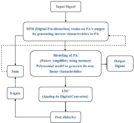
To implement practically, a feedback path needs to be employed after the power amplifier which consists of a RF downconverter and an ADC. The general block diagram of DPD proposed approach is shown below in Fig. 1.Fig. 1. Digital Pre-distorter (DPD) approach.
In the DPD approach, the output signal of the baseband PA model is fed to the input of the ADC. The LTE signal is also applied to the DPD input. The DPD then finds the error by using an algorithm i.e. Least Mean Square (LMS) in this paper and trains on it. For wide bandwidths, PAs start exhibiting the memory effects which induces due to the dependency of the non-linear behaviour of a power amplifier on the past values instead of only the present amplitude of the signal. Depending on this, the implementation of DPD is classified as the memoryless models and the models with memory. To model with memory, in this paper, memory polynomial model is used i.e. with memory effects. The post-distorter is replicated before the power amplifier as pre-distorter. This is indirect learning architecture. Thus, the input signal is first pre-distorted by the inverse block model and then fed to the PA model to have the desired output response. Then by estimation of the inverse of baseband PA iteratively, the desired pre-distorter could be found which can then be used to pre-distort any signal having an equivalent information measure for a given power amplifier.
If bandwidth, power and cost are of primary concern, a low-bit or low-resolution ADC can be used in the above scenario. It will allow to use the linearizer with smaller word-lengths and thus saves the power and area of the overall system. The main objective of this paper is testing the performance of two variations of DPD i.e. Full-band DPD and Sub-band DPD by altering the ADC bits (resolution) in the feedback path and to find the precision which would not affect the DPD overall performance.
III. SIMULATIONOFFULL-BANDDPD A full-band DPD is the one in which the entire LTE signal needs to be passed through the feedback path to be linearized. So, in this the entire transmit band near the main carriers is linearized [5]. It is responsible for the reduction of the spurious emissions i.e. spectral regrowth and the
intermodulation distortion (IMDs) near the main carrier. It is very important to consider the factor of carrier spacing while simulation because when the spacing between the carriers becomes large, it leads to greater computational complexity which results in greater power consumption and cost of ADC to implement the system. The block diagram of the Full-band DPD MATLAB simulation is shown in Fig. 2.
Fig. 2. Simulation of Full-band DPD
In this, two non-contiguous dual uplink LTE signals, each having 5 MHz bandwidth are taken for simulation. The generated LTE signal is then fed to a ninth-order and non-linear Power Amplifier (PA) modeled with the memory effects. The feedback path comprises of ADC (double precision) to quantize the feedback input to the DPD block by using a fixed-point toolbox.
[image:2.595.307.545.137.278.2]Fig. 3. Power Spectral Density (PSD) of Full-band DPD with 9th order PA.
Table- I: PSD of Full-band DPD with 9th order PA S. No. ADC Precision
(No. of bits)
Frequency (MHz)
Power (dBm)
1 No DPD 29.9706 -15.2995
2 64 29.9706 -26.772
3 8 29.9706 -26.772
4 6 29.9491 -26.7644
5 4 29.9491 -26.7644
6 2 29.9706 -26.772
7 1 29.9706 -26.772
[image:2.595.314.532.378.538.2]International Journal of Innovative Technology and Exploring Engineering (IJITEE) ISSN: 2278-3075,Volume-8 Issue-12, October 2019
The “comm.DPD” System object is then used to apply the DPD learning is using a memory polynomial to compensate for the non-linearities in the power amplifier. By taking double-precision ADC, values are computed by MATLAB. The ADC bits are further varied from 64-bits to 1-bit and by using the “comm.DPD” System object, we get the suppression depicted by the solid “red” curve in Fig. 3. From the results, it is seen that the performance of the system is almost identical. Thus, the in-built MATLAB DPD system object estimates the DPD and linearize the main carriers very efficiently as seen in the figure above.
We can conclude that the MATLAB “comm.DPD” system object efficiently linearizes the whole transmit band near the main carriers with the same efficiency by employing low-precision ADC, as low as 1-bit.
[image:3.595.314.532.240.593.2]IV. SIMULATIONOFSUB-BANDDPD In sub-band DPD, we have the flexibility to target a specific band around the main carrier instead of linearizing the entire signal at once which ultimately reduces the complexity when compared to the full-band DPD. So, the entire signal need not be passed through the feedback. In this, learning can be focused only on those bands i.e. sub-bands which are in violation of emission limits. A sub-band can be designed as shown in Fig. 4.
Fig. 4. Simulation of Sub-band DPD.
In this, we use an RF down-converter which can be tuned to the specific desired frequency of a violating spurious emission or intermodulation products like IMD3, IMD5 etc. It is followed by an analog low-pass filter (LPF) which is used for anti-aliasing and attenuation of the higher-power main carriers [5]. It makes its dynamic range high and due to which, this available range can be efficiently used with a low-precision ADC for receiving the desired spurious emission.
Similar to that of the full-band DPD system simulation, we consider here two non-contiguous LTE signals with each having 5 MHz bandwidth, which are broadcasted through a ninth-order power amplifier model. In this section, the simulation results are analyzed for sub-band DPD to target the right-hand third-order intermodulation (IM3+) spurious emission, left-hand third-order intermodulation (IM3-) spurious emission, the right-hand fifth-order intermodulation (IM5+) spurious emission and left-hand fifth-order intermodulation (IM5-) spurious emission respectively.
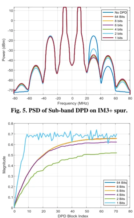
A. Right-hand third-order intermodulation (IM3+) Simulation is done to target the right-hand third-order intermodulation (IM3+) spurious emission with double-precision i.e. 64-bit ADC in the feedback path as
shown by the solid orange curve in the Fig. 5. below. Further to vary ADC precision, 64-bit values are converted to the signed fixed-point representation which results in addition of quantization noise. But as can be seen from the figure, it is seen that for a 1-bit ADC, the DPD performance degradation is insignificant, which is round about a 2 decibel (dB) difference in the suppression on IM3+ spur.
The convergence of the DPD coefficients for IM3+ spur can be seen in Fig. 6 in which it is observed that all DPD coefficients for ADC with bits greater than 2 converge smoothly i.e. the error signal is in correlation with the LMS reference signal which allows for smooth convergence even for low-dynamic range of the feedback path.
For 1-bit case, the DPD coefficients convergence is nearly smooth until few blocks but remains in the acceptable values despite having the lowest dynamic range of the feedback path.
Fig. 5. PSD of Sub-band DPD on IM3+ spur.
[image:3.595.57.287.370.507.2]ADC
[image:4.595.317.528.59.396.2]Fig. 7. PSD of Sub-band DPD on IM3- spur. The convergence of the DPD coefficients for IM3- spur is shown in Fig. 8. We see that all DPD coefficients for ADC with bits greater than 2 converge smoothly i.e. the error signal is in correlation with the LMS reference signal which allows for smooth convergence despite the low-dynamic range of feedback path and for 1-bit case, the DPD coefficients convergence remains in the acceptable values despite having the lowest-dynamic range.
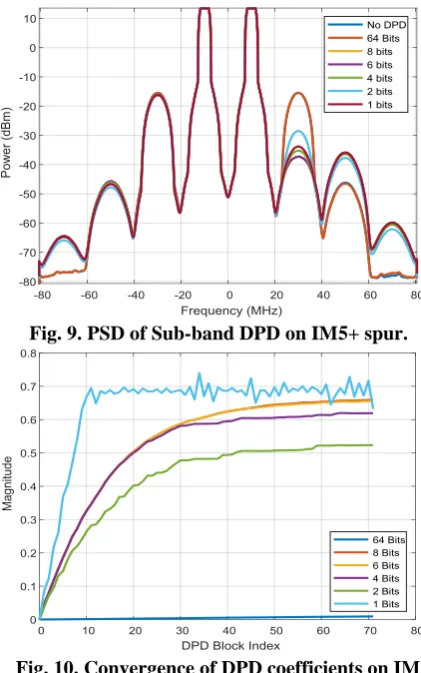
Fig. 8. Convergence of DPD coefficients on IM3- spur. C. Right-hand fifth-order intermodulation (IM5+) Simulation is done for the right-hand fifth-order intermodulation (IM5+) spurious emission. Using 64-bit ADC in IM5+, when the feedback into the DPD learning block is full, is shown by the solid orange curve in Fig. 9. Further by varying ADC precision and converting 64-bit values to signed fixed-point representation, quantization noise is introduced. From the results, it is seen that for a 2-bit ADC, the performance degradation is insignificant, nearly an 8.7-dB difference in the suppression on the right-hand IM3 spur as shown in Fig. 9.
[image:4.595.61.274.328.475.2]Fig. 10 shows the convergence of DPD coefficients for IM5+ spur. We see that all DPD coefficients for ADC with bits greater than 2, each converge smoothly i.e. the error signal is in correlation with the LMS reference signal which allows for smooth convergence despite the low-dynamic range of the feedback path. For 1-bit case, the convergence is nearly smooth and remains in the acceptable values despite being the lowest dynamic range.
Fig. 9. PSD of Sub-band DPD on IM5+ spur.
Fig. 10. Convergence of DPD coefficients on IM5+ spur.
D. Left-hand fifth-order intermodulation (IM5-) Simulation is done to target the left-hand fifth-order intermodulation (IM5-) spurious emission with double-precision i.e. 64-bit ADC in the feedback path as shown by the solid orange curve in the Fig. 11. below. Further to vary ADC precision, 64-bit values are converted to the signed fixed-point representation which results in addition of quantization noise. But as can be seen from the figure, it is seen that for a 4-bit ADC, the DPD performance degradation is insignificant, which is nearly a 0.4-dB) difference in the suppression on the IM5- spur.
[image:4.595.317.530.550.708.2]International Journal of Innovative Technology and Exploring Engineering (IJITEE) ISSN: 2278-3075,Volume-8 Issue-12, October 2019
Fig. 12. Convergence of DPD coefficients on IM5- spur. Fig. 12 shows the convergence of the DPD coefficients for IM5- spur and it is seen that for ADC with bits greater than 2, each converge smoothly i.e. the error signal is in correlation with the LMS reference signal which allows for smooth convergence despite the low-dynamic range and for 1-bit case, the convergence is nearly smooth and remains in the acceptable values despite being the lowest dynamic range of the feedback path.
So, sub-band DPD system is potentially less complex when compared to a full-band DPD system.
V. CONCLUSION
Digital Pre-Distortion is an extensively used technique to linear a power amplifier. In this paper, simulations are done for the full-band and sub-band DPD systems on 9th order power amplifier, by varying the ADC precision from 64 bits to 1 bit. After observations, it is found that with a low-precision ADC of even single bit, the performance of the full-band DPD training remains almost same which was initially restricted to 4 or 6 bits. For a sub-band DPD, it is analyzed that a 1-bit to 4-bit ADC is sufficient to suppress any of IMDs – IMD3+, IMD3-, IMD5+ or IMD5- spurious emission. It is an invaluable option to linearize those systems where complexity, power and cost are major concerns. In 5G systems, where it may not be efficient to perform a full resolution DPD for every transmit chain due to wide-bandwidths, sub-band DPD is a good choice.
REFERENCES
1. P. Asbeck and C. Fallesen, “A polar linearization system for RF power
amplifiers,” in Electronics, Circuits and Systems, ICECS 2000, 7th IEEE International Conference, 2000.
2. A. Katz, J. Wood and D. Chokola, “The evolution of PA linearization:
From classic feedforward and feedback through analog and digital predistortion” IEEE Microwave Magazine, vol. 17, pp. 32-40, 2016. 3. F. M. Ghannouchi, “Power amplifier and transmitter architectures for software defined radio systems” Circuits and Systems Magazine, IEEE, vol. 10, no. 4, pp. 56-63, 2010.
4. M. Abdelaziz, L. Anttila, C. Tarver, K. Li, J. R. Cavallaro and M. Valkama, “Low-Complexity subband digital predistortion for spurious emission suppression in noncontiguous spectrum access” IEEE Transactions on Microwave Theory and Techniques, vol. 64, pp. 3501-3517, 2016.
5. C. Tarver and J. R. Cavallaro, “Digital predistortion with low-precision
ADCs” in 2017 51st Asilomar Conference on Signals, Systems and
Computers, 2017.
AUTHORSPROFILE
Impreet Kaur received the B. Tech degree in
electronics and communication engineering from Punjab Technical University, Jalandhar in 2014, where she is currently pursuing the M. Tech degree from Punjabi University, Patiala, India.
Dr. Rajbir Kaur is an Assistant Professor in the Department of Electronics and Communication Engineering, in Punjabi University, Patiala, India.
Dr. Charanjit Singh is an Assistant Professor in the