White Rose Research Online URL for this paper:
http://eprints.whiterose.ac.uk/873/
Article:
Shen, J.X., Zhu, Z.Q. and Howe, D. (2002) Improved speed estimation in sensorless PM
brushless AC drives. IEEE Transactions on Industry Applications, 38 (4). pp. 1072-1080.
ISSN 0093-9994
https://doi.org/10.1109/TIA.2002.800778
[email protected] https://eprints.whiterose.ac.uk/
Reuse
Unless indicated otherwise, fulltext items are protected by copyright with all rights reserved. The copyright exception in section 29 of the Copyright, Designs and Patents Act 1988 allows the making of a single copy solely for the purpose of non-commercial research or private study within the limits of fair dealing. The publisher or other rights-holder may allow further reproduction and re-use of this version - refer to the White Rose Research Online record for this item. Where records identify the publisher as the copyright holder, users can verify any specific terms of use on the publisher’s website.
Takedown
If you consider content in White Rose Research Online to be in breach of UK law, please notify us by
Improved Speed Estimation in Sensorless PM
Brushless AC Drives
J. X. Shen, Member, IEEE, Z. Q. Zhu, Senior Member, IEEE, and David Howe
Abstract—The application of flux-observer-based sensorless control to permanent-magnet brushless ac motor drives is de-scribed. Current methods of speed estimation are assessed, both theoretically and experimentally, and an improved method, which combines the best features of methods in which speed is derived from the differential of rotor position and from the ratio of the electromotive force to excitation flux linkage, is proposed. Its performance is verified experimentally.
Index Terms—Brushless ac drives, flux observer, perma-nent-magnet machines, sensorless control, speed estimation.
I. INTRODUCTION
N
UMEROUS sensorless control techniques have been pro-posed for permanent-magnet (PM) brushless ac (BLAC) drives. Basically, however, these can be classified into two cat-egories: 1) those in which speed is estimated from an observer and the rotor position is obtained by integration [1]–[3] and 2) those in which the rotor position is estimated from an observer and the speed is calculated by differentiation [4]–[9]. However, in the first category, inaccuracies in the estimated rotor posi-tion may arise due to speed errors, the integraposi-tion of a constant error, for example, resulting in an unreliable estimate of rotor position unless an appropriate compensating algorithm is em-ployed. Similarly, in the second category, if the speed is derived simply from the differential of rotor position [6], [7], noise will be amplified and lead to errors in the estimated speed.When the rotor position is deduced directly from the observed flux vector, Lagerquist [10] recommended that the flux vector should be preprocessed with a low-pass filter to improve the ac-curacy of the derived position signal such that it can be differen-tiated for the estimation of speed. However, in a variable-speed BLAC drive, the use of a low-pass filter will generally intro-duce a phase shift to the fundamental flux vector over a wide frequency band. Thus, an average speed method is more widely used, since it gives the correct value when the motor operates at steady state. However, it is not usually used for speed feed-back in servo systems, since its dynamic response is generally not fast enough.
Paper IPCSD 02–033, presented at the 2001 IEEE International Electric Ma-chines and Drives Conference, Cambridge, MA, June 17–20, and approved for publication in the IEEE TRANSACTIONS ONINDUSTRYAPPLICATIONSby the In-dustrial Drives Committee of the IEEE Industry Applications Society. Manu-script submitted for review June 23, 2001 and released for publication May 17, 2002.
The authors are with the Department of Electronic and Electrical Engineering, University of Sheffield, Sheffield S1 3JD, U.K. (e-mail: [email protected]; [email protected]; [email protected]).
[image:2.612.318.536.168.282.2]Publisher Item Identifier 10.1109/TIA.2002.800778.
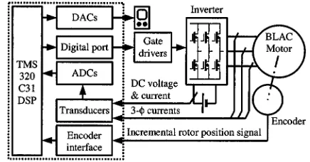
Fig. 1. Block diagram of DSP-controlled BLAC drive system.
An alternative approach, proposed by Watanabe [11] and Matsui [4], [5], is to determine the speed from the ratio of the amplitude of the induced electromotive force (EMF) to the excitation flux linkage. However, while this method of speed estimation has a fast response, it has two significant drawbacks. Firstly, the calculation of the EMF requires the differential of the current. Thus, noise can cause a potentially significant speed error. While Sharkh [12], [13] eliminated the need for the differential, this resulted in a significantly more complex control system design. Kim [14], on the other hand, assumed that the current was constant at the end of each flux observing step, so that its differential was zero. However, in general, such an assumption is not appropriate. Secondly, parameters, such as the winding resistance, inductance, and excitation flux linkage, may vary, due, for example, to variations in temperature and saturation, and cause further errors in the estimated speed. Thus, Kim [14] also compensated for parameter variations, using the estimated average speed as the compensation refer-ence (i.e., input variable). However, it is difficult to compensate for variations in three parameters from only one input variable. In general, the derivation of the speed from the estimated rotor position results in significant noise. Further, while the estima-tion of the average speed may be accurate under steady-state operating conditions, it is usually not fast enough to give good dynamic response. In contrast, the estimation of the speed from the induced EMF and excitation flux linkage results in fast dy-namic response but low accuracy. Therefore, the development of an improved speed estimation method is of considerable in-terest.
In this paper, the basic principle of flux-observer-based sen-sorless control is briefly described, and the performance of an improved speed estimation method, which combines the best features of the foregoing methods, is demonstrated.
The investigation utilizes a TMS320C31 digital-signal-pro-cessor (DSP)-based drive as shown in Fig. 1, which supplies a
TABLE I
SPECIFICATION OFBLAC MOTOR
Fig. 2. Phasor diagram of BLAC motor.
two-pole surface-mounted PM BLAC motor. The motor speci-fication is given in Table I. An encoder is used to measure the actual rotor position and to deduce the speed from the differ-ential of position, and these are compared with values obtained from the existing and proposed sensorless techniques.
II. FLUX-OBSERVER-BASEDSENSORLESSCONTROL
The phasor diagram of a BLAC motor is shown in Fig. 2, the current vector ( ) and the voltage vector ( ) being derived from measured phase currents, the dc-link voltage and the inverter switching vector, and the transformation matrix from the – – reference frame to the stationary – reference frame. The vector represents the resultant stator winding flux linkage, while the vector represents the excitation flux linkage due to the permanent magnets, which is in phase with the rotor axis. Hence, the rotor position can be obtained from the estimated phase angle .
Since
(1)
where is the winding resistance, then is observed from
(2)
With zero current in the stator windings, the stator flux-linkage vector is simply the excitation flux-linkage vector, i.e.,
, which is obtained by initially aligning the rotor before the flux observer is applied.
From Fig. 2, it is seen that can be calculated from , the current vector , and winding inductance. Further, if sur-face-mounted magnets are employed, saliency can be neglected,
, and is simply calculated from
(3)
In the – reference frame, is expressed by the projec-tions and on the and axes, as shown in Fig. 2. Therefore, the rotor position is obtained as
(4)
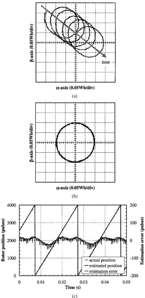
Fig. 3(a) shows the locus of the observed flux vector for the experimental drive system. As will be seen, while it is al-most circular, it is continuously being displaced, due to the in-tegration in (2), which amplifies any dc offset or error in the measured currents until saturation is reached. Clearly, it is not possible to deduce the rotor position from such a changing flux vector locus. Thus, a high-pass filter, having the transfer func-tion , is applied to the variables to be integrated. Since the transfer function of a pure integrator is , the resultant transfer function is , which is equivalent to replacing the integrator by a low-pass filter [15]. Hence, (2) becomes
(5)
With the cutoff frequency in the experimental drive set at 9.4 rad/s, the circular locus of the observed flux vector remains stable, as shown in Fig. 3(b). The estimated rotor position and the actual position, expressed in terms of the encoder resolution of 4000 pulses per revolution, are compared in Fig. 3(c), the maximum difference being 50 pulses, or 4.5 electrical, which is sufficiently accurate for the vector control of most servo drives.
III. SPEED ESTIMATION FROMDIFFERENTIAL OF
ROTORPOSITION
The rotor angular velocity is given by
(6)
where and are the instantaneous rotor positions at the start and end of the th time interval , respectively. Since, in general, errors will exist in and , then
(a)
(b)
[image:4.612.47.284.59.546.2](c)
Fig. 3. Results from flux-observer-based position estimation. (a) Locus of observed excitation flux-linkage vector, without high-pass filter. (b) Locus of observed excitation flux-linkage vector, with high-pass filter. (c) Comparison of actual and estimated rotor position, with high-pass filter but without flux filter, 3000 r/min.
where is the actual rotor position and is a posi-tion error. Although may be very much smaller than the range of (i.e., 4000 pulses), is small since is very short. Therefore, may be comparable with , and cause a significant error in the estimated speed. If the motor speed is r/min,
[image:4.612.310.548.62.206.2]pulses. Since ms in the experimental system, the speed is calculated as r/min. Thus, if the actual speed is 3000 r/min, is 600 pulses. However, from Fig. 3(c) it is seen that can be 50 pulses. Hence, the error in the estimated speed may be 250 r/min, or 8%. Clearly,
Fig. 4. Derivation of speed from the differential of estimated rotor position.
the error may be much higher at lower speeds, when may be more comparable with .
While the error could be reduced by increasing the sampling time interval , this would compromise the dynamic response of the speed estimation, and is not an acceptable solution.
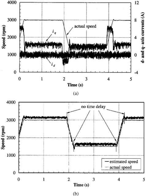
In order to demonstrate the limited performance of this speed estimation method, the commanded speed of the experimental drive was changed from 1500 to 3000 r/min every 2 s, a fuzzy logic algorithm being employed for speed control [16]. The en-coder output was used for the vector control, as well as for the measurement of the actual speed for the speed control system. In addition, the rotor position was estimated as described in Sec-tion II, and the speed was estimated from the differential of the estimated rotor position. Fig. 4 shows that the estimated speed contains significant ripple, and would be inappropriate for speed feedback in a sensorless drive system.
IV. FILTERING OFOBSERVEDFLUXVECTOR
(a) (b)
(c) (d)
[image:5.612.55.535.58.538.2](e)
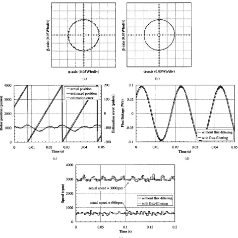
Fig. 5. Influence of low-pass filter on observed flux-linkage vector. (a) Locus of observed flux-linkage vector without flux filter, 3000 r/min. (b) Locus of observed flux-linkage vector with flux filter, 3000 r/min. (c) Comparison of actual and estimated rotor position, with flux filter, 3000 r/min. (d) Observed fluxes ( ), with and without flux filter, 3000 r/min. (e) Speed estimation with and without flux filter, 3000 and 600 r/min.
variations in the position error, shown in Figs. 3(c) and 5(c), which are caused by the periodic variation of the motor parameters (such as the change in inductance due to saturation) and thus have a frequency which is comparable with the fundamental flux vector, and which cannot be eliminated by the flux filter. Moreover, the amplitude of the low-frequency components is approximately proportional to the armature current. Thus, the position error and speed error become more significant when the load torque is increased.
In summary, filtering of the observed flux vector may intro-duce a significant phase shift, and be ineffective in reducing the speed error at high speed. Furthermore, as will be seen in the next section, the flux filter has relatively little effect on im-proving the estimated average speed.
V. AVERAGESPEEDESTIMATION
Fig. 6. Influence of flux filter on estimated average speed when low-pass speed filter is employed, 3000 and 600 r/min.
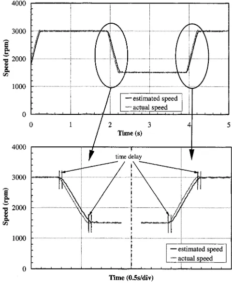
Fig. 7. Average speed estimation.
The experimental procedure which was described earlier to obtain Fig. 4 was again implemented, and the estimated av-erage speed was compared with the actual speed, as shown in Fig. 7, from which it will be seen that is in close agreement with the actual speed under steady-state operating conditions. However, it will also be observed, in the lower section of Fig. 7, that there is a noticeable time delay in the estimated speed.
In general, the predicted average steady-state speed is accu-rate, and unlike the flux filter, the speed filter does not introduce a phase shift in the observed flux-linkage vector. However, since it causes a time delay in the estimated speed, it may compromise the dynamic response of a drive. Thus, this method of speed estimation may also be unsuitable for speed feedback in servo controlled drives.
VI. SPEEDESTIMATION FROMINDUCEDEMFAND
EXCITATIONFLUXLINKAGE
If the excitation flux linkage is known a priori and the ampli-tude of the induced EMF ( ) is deduced from the measured current and voltage, then since the two are related in the rotor
– reference frame by
(8)
where is the stator winding inductance, as-suming a surface-mounted magnet rotor, the speed may be esti-mated from
(9) The main merit of estimating the speed in this way is that it leads to a fast response. In the experimental drive system, it was estimated every 50 s, the same frequency as the rotor position estimation. However, it has two significant drawbacks. Firstly, the parameters , , and are sensitive to variations in temperature and saturation, and although Kim [14] compen-sated for such parameter variations, this is difficult to imple-ment, as mentioned earlier. Secondly, the speed estimation still involves a differential operation. Thus, for a surface-mounted magnet motor, for which the winding inductance is usually rel-atively small, and the phase currents may contain a significant ripple, the differential operation can cause a significant error in the estimated speed. This is evident in Fig. 8(a), which shows the - and -axes currents ( and ), calculated from the mea-sured phase currents, when the motor speed was changed from 1500 to 3000 r/min, as described earlier.
Since the estimation of speed from the induced EMF and ex-citation flux linkage is inherently inaccurate, a further variant,
viz. eliminating the differential operation in (9), has been
inves-tigated so as to simplify the calculation. While this increases the potential for error in the estimated speed, it ensures fast response. Moreover, since, in a surface-mounted magnet motor, is usually much smaller than , especially when the -axis current reference is set to zero in the vector control, (9) may be simplified to
(10)
[image:6.612.45.285.260.553.2](a)
[image:7.612.309.546.59.377.2](b)
Fig. 8. Estimation of speed from EMF and excitation flux. (a)d-axis and
q-axis currents, rich of noise. (b) Comparison of estimated and actual speed.
VII. IMPROVEDMETHOD OFSPEEDESTIMATION
From the results presented in Figs. 7 and 8, the following con-clusions can be drawn: 1) a phase difference exists between the estimated average speed, , derived from the differential of the estimated rotor position and the actual speed and 2) a magnitude error exists between the actual speed and the estimated speed, , derived from the induced EMF and excitation flux-linkage. Thus, neither method is entirely suitable for speed feedback. However, the two methods can be combined to improve the es-timation of the speed.
The following improved estimation of rotor speed, , is pro-posed:
(11)
If , then . Thus, under steady-state operation, plays the dominant role in the speed estimation. However, if
, then . Hence, under transient conditions, plays the dominant role. Equation (11) can be re-expressed as
(12)
Thus, the proposed speed estimation method compensates the average speed by adding , where is the output of the high-pass filtering of .
(a)
(b)
Fig. 9. Performance of improved speed estimation method. (a) Time constant
T = 10 s. (b) Time constant T = 100 s.
[image:7.612.44.282.65.384.2](a) (b)
(c) (d)
[image:8.612.54.539.62.543.2](e)
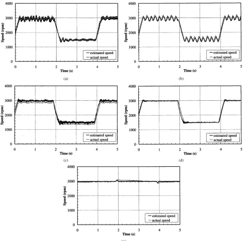
Fig. 10. Speed control performance with different sensorless speed feedback methods. (a) Speed feedback derived from differential of estimated rotor position (! ), changing speed command. (b) Speed feedback using estimated average speed (! ), changing speed command. (c) Speed feedback derived from EMF and excitation flux linkage (! ), changing speed command. (d) Speed feedback using improved method of speed estimation (! ), changing speed command. (e) Speed feedback using improved method of speed estimation (! ), 3000 r/min, changing load torque.
is not critical since reflects the change in the actual speed. However, when the time constant is set to a small value, such as 10 s, decreases quickly from 450 r/min and unex-pectedly reaches zero during the transient period [Fig. 9(a)], such that the speed compensation disappears and is consid-erably in error from the actual speed. Moreover, between this transient period and the next steady-state period, a step change in from 300 to 150 r/min occurs, which results in an in-crease of 450 r/min in . Thus, is overcompensated, and is further from the actual speed. During the steady-state period from 2.2 to 3.9 s, however, decreases from 450 r/min to zero, and becomes equal to the actual speed. Consequently, as can be seen, a significant error exists in the estimated speed
to zero, when corresponds to the actual speed. In summary, errors in the estimated speed at the beginning of each steady-state operating period can be significantly reduced by choosing an appropriate time constant , and the estimated speed by the proposed method agrees well with the actual speed, espe-cially during steady-state operation. Thus, it can be employed for speed feedback in a sensorless drive system.
VIII. SENSORLESSSPEEDCONTROL
In order to demonstrate the performance of the four methods of speed estimation which have been considered when they are employed in a closed-loop speed-controlled brushless drive, the load torque was maintained constant while the commanded speed was varied between 1500–3000 r/min every 2 s, fuzzy logic control being employed for the speed control. The drive was the same as that which was used to obtain the results shown in Figs. 4 and 7–9, except that the estimated speed (i.e., , , , and ) is now employed for speed feedback rather than the actual speed as in the previous tests.
As will be seen in Fig. 10(a), when the speed feedback was derived from the differential of the estimated rotor position, the speed exhibited a significant high-frequency oscillation as well as a low-frequency ripple, while when the estimated average speed was employed as feedback (Fig. 10(b)) the speed was unstable. When the speed feedback was derived from the induced EMF and excitation flux linkage, although the dynamic response was good, a speed error as well as a small speed ripple existed during steady-state operation, as will be seen in Fig. 10(c). However, when the proposed method of speed estimation was employed as speed feedback, the steady-state speed error was very small, and the dynamic response was good, as shown in Fig. 10(d).
In a further test to demonstrate the performance of the pro-posed method of speed estimation, the commanded speed was set at 3000 r/min, and the load torque was switched on and off every 2 s. As will be seen in Fig. 10(e), the dynamic and steady-state speed errors were very small.
IX. CONCLUSIONS
Various methods for estimating the speed of a sensorless BLAC motor drive have been implemented and compared. Al-though the estimation of the average speed from the differential of the rotor position is adequate for steady-state operation, phase delay compromises the system dynamic performance. In contrast, while the estimation of the speed from the EMF and excitation flux linkage has a fast response, the steady-state performance is compromised by the ripple and error in the estimated speed. The proposed method of speed estimation combines the best features of the average speed estimation and the EMF and flux-based estimation methods, and has been shown to yield improved performance. It is, therefore, eminently suitable for closed-loop speed control.
REFERENCES
[1] M. H. Park and H. H. Lee, “Sensorless vector control of permanent magnet synchronous motor using adaptive identification,” in Proc. IEEE
IECON’89, 1989, pp. 209–214.
[2] V. Sadasivam and L. Xu, “A robust position sensorless vector control of permanent magnet machines by torque angle estimation,” in Proc. IEEE
Int. Conf. Power Electronics and Drives System, 1997, pp. 524–529.
[3] K. Tatematsu, D. Hamada, K. Uchida, S. Wakao, and T. Onuki, “Sen-sorless control for permanent magnet synchronous motor with reduced order observer,” in Proc. IEEE PESC’98, 1998, pp. 125–131. [4] N. Matsui and M. Shigyo, “Brushless DC motor control without position
and speed sensor,” IEEE Trans. Ind. Applicat., vol. 28, pp. 120–127, Jan./Feb. 1992.
[5] N. Matsui, “Sensorless PM brushless DC motor drives,” IEEE Trans.
Ind. Electron., vol. 43, pp. 300–308, Apr. 1996.
[6] T. H. Liu and C. P. Cheng, “Controller design for a sensorless permanent-magnet synchronous drive system,” Proc. Inst. Elect. Eng., pt. B, vol. 140, pp. 369–378, Nov. 1993.
[7] T. Senjyu, T. Shimabukuro, and K. Uezato, “Vector control of perma-nent magnet synchronous motors without position and speed sensors,” in Proc. IEEE PESC’95, 1995, pp. 759–765.
[8] L. Xu and C. Wang, “Implementation and experimental investigation of sensorless control schemes for OMSM in super-high variable speed operation,” in Conf. Rec. IEEE-IAS Annu. Meeting, 1998, pp. 483–489. [9] D. Yousfi, M. Azizi, and A. Saad, “Position and speed estimation with improved integrator for synchronous motor,” in Proc. IEEE IECON’99, vol. 3, 1999, pp. 1097–1102.
[10] R. Lagerquist, I. Boldea, and T. J. E. Miller, “Sensorless control of the synchronous reluctance motor,” IEEE Trans. Ind. Applicat., vol. 30, pp. 673–682, May/June 1994.
[11] H. Watanabe, S. Miyazaki, and T. Fujii, “Improved variable speed sensorless servo system by disturbance observer,” in Proc. IEEE
IECON’90, 1990, pp. 40–45.
[12] S. M. A. Sharkh and V. Barinberg, “A new approach to rotor position estimation for a PM brushless motor drive,” in Proc. 9th Mediterranean
Electrotechnical Conf., 1998, pp. 1199–1203.
[13] , “Design and performance of a new technique for sensorless con-trol of a downhole brushless PM motor,” in Proc. IEE Power Electronics
and Variable Speed Drives Conf., 1998, pp. 263–268.
[14] J. S. Kim and S. K. Sul, “New approach for high-performance PMSM drives without rotational position sensors,” IEEE Trans. Power
Elec-tron., vol. 12, pp. 904–911, Sept. 1997.
[15] H. Tajima and Y. Hori, “Speed sensorless field-orientation control of the induction machine,” IEEE Trans. Ind. Applicat., vol. 29, pp. 175–180, Jan./Feb. 1993.
[16] J. X. Shen, Z. Q. Zhu, and D. Howe, “Hybrid PI and fuzzy logic speed control of PM brushless AC drives,” in Proc. 9th European Conf. Power
Electronics and Applications, 2001, CD ROM.
J. X. Shen (M’98) was in born in Zhejiang Province,
China, in 1969. He received the B.Eng. and M.Eng. degrees from Xi’an Jiaotong University, Xi’an, China, in 1991 and 1994, respectively, and the Ph.D. degree from Zhejiang University, Hangzhou, China, in 1997, all in electrical engineering.
Z. Q. Zhu (M’90–SM’00) received the B.Eng. and
M.Sc. degrees from Zhejiang University, Hangzhou, China, in 1982 and 1984, respectively, and the Ph.D. degree from the University of Sheffield, Sheffield, U.K., in 1991, all in electrical and electronic engi-neering.
From 1984 to 1988, he lectured in the Department of Electrical Engineering, Zhejiang University. Since 1988, he has been with the University of Sheffield, where he is currently a Professor of Electronic and Electrical Engineering. His current major research in-terests include applications, control, and design of permanent-magnet machines and drives.
Prof. Zhu is a Chartered Engineer in the U.K. and a member of the Institution of Electrical Engineers, U.K.
David Howe received the B.Tech. and M.Sc. degrees
from the University of Bradford, Bradford, U.K., in 1966 and 1967, respectively, and the Ph.D. degree from the University of Southampton, Southampton, U.K., in 1974, all in electrical power engineering.
He has held academic posts at Brunel and Southampton Universities and spent a period in industry with NEI Parsons Ltd., working on electro-magnetic problems related to turbo-generators. He is currently a Professor of Electrical Engineering at the University of Sheffield, Sheffield, U.K., where he heads the Electrical Machines and Drives Research Group. His research activities span all facets of controlled electrical drive systems, with particular emphasis on permanent-magnet excited machines.