Viewing Thick and Irregular Object from
Reflecting Light Compound Microscope using
3D Image Processing Algorithm
Dharmishtha T. Dhimmar1, Himanshu S Mazumdar2
Student, Department of Information Technology, Dharmsinh Desai University, Gujarat, India1 Head, Research and Development Center, Dharmsinh Desai University, Gujarat, India2
ABSTRACT: Microscopes are widely used to view magnified image of objects in different studies like morphological imaging, living cells viewing, geological survey and rock identification.While working with irregular object, images are often degraded due to uniform focusing and illumination problems. The main causes of image degradation are due to different types of blur and noise introduced by different systems, devices or operations. The deconvolution is an operation used in such image restoration to recover an image from an object that is degraded by blurring and noise. Blind deconvolution is the image restoration algorithm where the parameters responsible for blur are unknown. In our proposed method, a series of digital images of the target object are acquired corresponding to different focal planes. A multilayer neural network is trained with a known training dataset for which the 3D coordinates of target object are available. In this process, the neural network models blind deconvolution from training dataset .When presented with unknown sample, the trained neural network identifies focused pixels of all image stacks. The fully focused image is reconstructed from focus scanned image stack of target irregular object by combining focused pixels of all stacked images. This also provides z-coordinates of pixels from the stack id for 3D viewing.
KEYWORDS:2D, 3D, Image stacking, Neural Network, microscope, point spread function, edge enhancement, shadow correction, focus correction, intensity normalization
I. INTRODUCTION
Most commonly used microscopes in educational institutes and laboratories are bright field compound microscope. In bright field microscopes, the specimen is dark and contrasted by the surrounding bright viewing field. These microscopes use magnification of 10x to 2000x [2] and are back illuminated for desired contrast. In most cases it needs elaborate sample preparation to present the object in a plane. This is required to get uniform focusing of the sample surface. There are other special microscope which works on concept of point scan and can visualize irregular surface at high magnification. The confocal microscope [3] uses an optical imaging technique used to increase optical resolution and contrast by using point illumination. In confocal microscope, an image is constructed by suppressing signal coming from out-of-focus planes. This is achieved by using a pinhole in front of the detector. Light originating from an in-focus plane is imaged by the microscope objective such that it freely passes the pinhole, whereas light coming from out-of-focus planes is blocked by the pinhole. These microscopes creates sharp image of an object that would appear blurred when seen by a conventional microscope. The confocal microscope provides high magnification from 108x upto 17,280x [1]. However, these microscopes are complex, expensive and not easily affordable by majority of researchers.
communities. Observing thick and irregular surface through popular compound microscopes are difficult due to uniform illumination and focusing problems. A novel technique is described in this paper to overcome above problems of uniform focusing and illumination while viewing rough surface like rocks and biological samples through popular compound microscopes. In our research, we demonstrate fully focused and uniformly illuminated output image of rough surfaces through popular compound microscope. We also artificially enhance the contrast of the object with background. This is achieved by stacking multiple images for different focal planes. In each plane, multiple images are taken with different illumination source at different angle. Neural network algorithms are used for different tasks like focus detection, shadow detection, intensity normalization and edge enhancement.
LITERATURE SURVEY
There is awareness and demand of 3D microscopy in the country. Existing solutions like confocal microscopy is an optical imaging technique used to increase optical resolution and contrast by using point illumination and a spatial pinhole to eliminate out-of-focus light in specimens that are thicker than the focal plane. It enables the reconstruction of three-dimensional image of an object. As only one point in the sample is illuminated at a time, 2D or 3D imaging requires scanning over a regular raster sequentially in the specimen. This solution is found very expensive (35 to 70 lakhs INR and to be imported), bulky and slow.
Compound microscopes are most popular and commonly used for applications like morphological imaging, living cells viewing, geological survey and rock identification. While observing thick and irregular surface in compound light microscope, it is observed that all elements of the object are not fully focused at any focal length. Due to small depth of field, image of irregular surface is not fully focused in single image using compound light microscope. Therefore partially focused stack of images are generated at different focal planes. The noise removal from all stacked images is a key issue for reconstruction of crisp image. To improve quality of image and to extend depth of field, image deconvolution (deblurring) algorithm is used.
The image of an object seen by microscope is convolution of original image and point spread function. PSF is a model of how one point is imaged by microscope. PSF is used in image deconvolution algorithm to restore original image of an object. Deconvolution refers to the computational process of recovering the original signal or image from given degraded observations. There are major two categories of image deconvolution algorithms: A Non Blind Image Deconvolution and Blind Image Deconvolution. A non-blind deconvolution requires knowledge of PSF. The non blind image deconvolution algorithms [11] like no-neighbors methods, neighboring methods, linear methods, nonlinear methods, statistical methods are easy to use but takes more time, complex and not providing good result on some images. Performance of all the non blind image deconvolution algorithms depends on accurate PSF modeling, which is a challenging task in a real imaging scenario. The blind image deconvolution algorithms like A Priori Blur Identification Methods, The Iterative Blind Deconvolution Method [10], The multichannel Blind Deconvolution [9], Blind Deconvolution Scheme Using Recursive Filtering [6], Richardson Lucy Algorithm [4], Blind Deconvolution with Canny Edge Detection Technique [7] are most popularly used in different areas to deblur images. These blind deconvolution algorithms do not require knowledge of PSF but are computationally intensive [11]. We have used multilayer neural network which identifies focused pixels of all image stacks of target object. The neural network models blind deconvolution from training dataset. The important reason of using neural network is to get correction model that is independent of specimen type
.
The fully focused image is reconstructed from focus scanned image stack of target irregular object by combining focused pixels of all stacked images.II. PROPOSED METHOD
Figure-1 Shows Ray Diagram of Compound Microscope having Objective lens of Short Focal Length (fo) and Eyepiece of Long Focal Length (fe)
In transmitted light microscope, the light is transmitted from a light source on the opposite side of lens. As the light passes through the specimens, only transparent and translucent objects can be examined. Opaque specimens are not suitable to observe by this transmitted light microscope. The compound microscope uses two lenses as shown in figure-1 to magnify image of an object. The objective lens forms a real inverted image of an object at I1.Then eyepiece produces a virtual image of I1.The magnification (M) of compound light microscope is given by the equation
M = fe / fo (1)
A larger eyepiece focal length does result in larger magnification. Beyond 2000X magnification, target object comes very close to objective lens of microscope. Hence,compound microscopes have limit of maximum magnification up to 2000X [2]. It is used to study bacteria, algae, protozoa and a variety of human and animal cells. Viruses and atoms are beyond the capabilities of compound microscope because these objects are smaller than wavelength of visible light (around 103 nm).
The objective of this paper is to view 3D image of opaque and irregular surface in compound light microscope using advanced image processing algorithms.
In following sections we discuss modifications in standard compound light microscope to achieve uniform focusing for irregular surface and enhance its performance for observing thick samples of different application areas.
2.1 DEVELOPMENT OF FOCUSING ARRANGEMENT
Figure-2 Shows add on Components to Compound Light microscope for 3D Visualization of Irregular object
It is difficult to manually acquire image stack at uniform depth by manually rotating focusing knob of microscope. This operation is done automatic by connecting stepper motor drive to focusing knob of microscope through timing belt as shown in figure 2. A stepper motor of 200 steps per revolution is used to drive the focusing knob of microscope. An arduino microcontroller board is used to implement automatic focus scan between the top and bottom limits with programmable step size. The IR sensors and stepper motor are operated by transferring commands from host PC to arduino microcontroller board via HC-05 bluetooth module. The number of stacks between the top and bottom limits defines number of images per stack. The camera connected to host PC captures images at different focal planes and generate image stack of the target object.
2.2 DEVELOPMENT OF FRONT ILLUMINATION
In compound microscope, only transparent and translucent objects can be seen due to back illumination. Front illumination is required to visualize image of opaque objects in compound light microscope. Hence it needs front illumination in existing transmitted light microscope. The object is front illuminated from different angles using multiple programmed LEDs. The LEDs are placed in shape of ring around objective lens of microscope.
2.3 SHADOW DETECTION
2.4 INTENSITY NORMALIZATION
The microscopic images have poor contrast due to illumination conditions and camera resolution. Intensity Normalization is image enhancement technique to improve contrast of an image by normalizing intensity values in an image. Global techniques are fast and simple, and are suitable for overall enhancement of the image but these techniques cannot adapt to local brightness features of the input image [15]. Local enhancement techniques can enhance overall contrast more effectively but its computational cost is very high. Histogram equalization technique is widely used because it is simple to use and gives better performance [16]. This technique enhances borders and edges among objects in an image. We have calibrated the entire illumination process on white flat object. A series of images corresponding to each LED contribution is recorded. The resultant image for each LED contribution is corrected for normalized uniform intensity. A correction factor corresponding to each pixel is stored for intensity normalization operation of object image.
2.5 EDGE ENHANCEMENT
If an object and background are of same color, it is difficult to distinguish object from background after shadow detection and removal. Therefore shadow is removed in such a way that the edges are preserved. A sobel and prewitts, classical edge detectors are simple but they are sensitive to noise [14]. Laplacian of Gaussian edge detector finds the correct places of edges but it is malfunctioning at the corners and curves. A canny edge detector has improved high signal to noise ratio and detect edges in noise conditions also but it takes more time because of complex computation [17].
2.6 FOCUS DETECTION
While observing thick and irregular surface in compound light microscope, it is observed that all elements of an object is not fully focused at any focal length setting. Therefore partially focused images corresponding to different focal planes are generated in an image stack
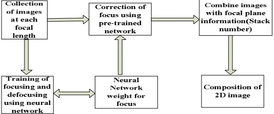
Figure 3 Shows the Block diagram of Focus Correction in Standard Compound Light Microscope
(a) (b)
Figure 4(a) Shows Fully Focused Digital Microscope Image of Flat Rock Grain. Figure 4(b) shows Fully Defocused Digital Microscope Image of Flat Rock Grain
The neural network once trained with sample of figure 4(a) and 4(b) is capable of distinguishing or classifying focused segment from defocused segment in an image stack of an object as shown in figure 5(a) and 5(b).
(a) (b)
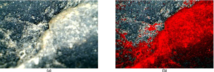
5 (a) Shows one of the Partially Focused Irregular Rock Grain Image taken using Digital Microscope for Testing Neural Network. Figure-5(b) shows the Trained Neural Network Output of Figure 5(a) identifying the Defocused patches in Red Color
2.6.1 FOCUS TRAINING OF NEURAL NETWORK FOR 2D IMAGING
Figure 6 Shows architecture of Multilayer Neural Network with Backpropagation Learning Algorithm
A randomly chosen 5x5 image segment within randomly selected image is applied as input to neural network. The corresponding desired output being 1 or 0 corresponding to focused or defocused image. The training is performed separately for red, green and blue spectral component of input image. The backpropagation algorithm used for experiment is given below.
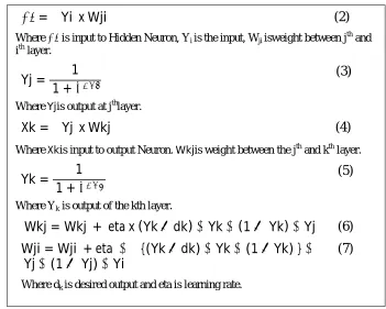
Figure 7 Shows Backpropagation Neural Network Algorithm. Forward update is shown in eq.(2),(3),(4),(5) and backpropagation error correction is shown in eq.(6) for k and j layer correction and eq.(7) for i and j layer correction
=
∑Yi x Wji
(2)
Where is input to Hidden Neuron, Yi is the input, Wji isweight between jth and ith layer.
Yj =
1
1 +
(3)
Where Yjis output at jth layer.
Xk =
∑Yj x Wkj
(4)
Where Xkis input to output Neuron. Wkjis weight between the jth
and kth layer.
Yk =
1
1 +
(5)
Where Yk is output of the kth layer.
Wkj = Wkj
+
eta x (Yk
−
dk)
∗ Yk
∗
(1
− Yk)
∗ Yj
(6)
Wji = Wji
+ eta ∗ ∑{(Yk
−
dk)
∗ Yk
∗ (1
−
Yk) }
∗
Yj
∗
(1
− Yj)
∗ Yi
Where dk is desired output and eta is learning rate.
A real time dataset is generated by placing the object shown in figure 4(a) inclined position with 20 degree inclination to get live online training data from the microscope camera. The focal length is estimated from inclined geometry.
2.6.2 FOCUS CORRECTION USING NEURAL NETWORK FOR 2D IMAGING
The trained focus correction neural network learns to extract the ideal image equivalent to the image of focal plane. This correction reduces the number of images by factor of images in vertical stack.
2.6.3 FOCUS CORRECTION NEURAL NETWORK FOR 3D IMAGING
This is similar to the 2D focus correction neural network except the backpropagation correction is not applied. In this, desired output is single binary output representing focus or defocus state. Each focused pixel is replaced by 3D pixel coordinate corresponding to its stack number as z coordinate. The 3D image of target object is generated by appropriately combining all the 3D pixels of all image stack.
2.6.4 3D VISUALIZATION
The 3D coordinates generated from focus correction neural network algorithm is used to generate 3D view of different look angles using openGL graphics technology along with .Net framework. An openGL is an environment for developing 2D and 3D graphics application programming interface.
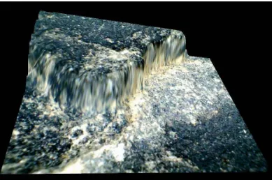
Figure 8 Shows 3D Projection of Image shown in Figure-5 using Height Information derived from Defocused Plane
III. RESULTS AND DISCUSSION
(a) (b)
Figure 9(a) Shows few partially focused image stack of mustard seed using upgraded compound light microscope as shown in figure (2). Figure 9(b) Shows fully focused image of mustard seed (rough and irregular object)
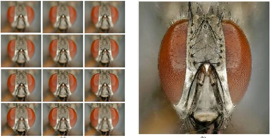
(a) (b)
Figure 10 (a) Shows few partially focused image stack of fly eye taken from internet source. Figure 10 (b) Shows fully focused image of Fly eye (rough and irregular object)
IV. CONCLUSION
The bright field compound light microscopes are most commonly used in different areas. However, these microscopes cannot visualize irregular surface of opaque objects at high magnification. The compound microscope with add on focusing and front illumination arrangement is developed for 3D visualization of rough and/or irregular surface. In our research, fully focused and uniformly illuminated output 3D image of irregular surface is generated using relatively low cost compound light microscope. While observing thick and irregular surface in compound light microscope, it is observed that all elements of the object are not fully focused at any focal length setting. Therefore partially focused image stack of target object is generated at different focal planes. The trained neural network is used to identify focused pixels of image stack. The fully focused image of target object is generated by combining all the focused pixels from image stack of an object. The stack number of each focused pixels is considered as z coordinate for 3D visualization of target object. The microscope used for the experiment is of lowest cost range of 3000 rupees without camera and additional hardware of microscopic camera and stepper motor add ons of rupees 6000. This microscope is affordable by individual researchers and useful to many researches that are dependent on confocal microscope.
ACKNOWLEDGMENT
The authors wish to thank staff of Research and Development Center, Dharmsinh Desai University, for their kind support, valuable guidance and providing all facilities for conducting experiments. Special thanks are given to Ms. Krutika Panchal for providing hardware and software support in microscope data acquisition. We sincerely thank Department of Science and Technology, Government of India,for funding this project.
REFERENCES
[1]Lab Manual of “OlympusLEXT OLS4000 3D Confocal Laser Microscope”
[2]http://www.labessentials.com/microscopes_compound_basics.html
[3]Claudette M. St., Croix, Stuart H. Shand and Simon C. Watkins, ”Confocal microscopy: comparisons, applications and problems”, The International Journal of Life Science Methods, Vol. 39, Issue 6, pp. S2–S5,2005.
[4] Fan, Kecheng Yang, Min Xia, Wei Li, Bo Fu And Wei Zhang, "Comparative study on several blind deconvolution algorithms applied to underwater image restoration", Springer , Vol. 17, Issue 3, pp 123-129 , 05 June 2010
[5]Jeongtae Kim,*Suhyeon An, Sohyun Ahn, Boyoung Kim, ”Depth-variant deconvolution of 3D widefield fluorescence microscopy using the penalized maximum likelihood estimation method ",Vol. 21, Issue 23, pp. 27668-27681,2013
[6]Deepa Kundur, Dimitrios Hatzinakos, "A Novel Blind Deconvolution Scheme for Image Restoration Using Recursive Filtering", IEEE Transactions On Signal Processing, Vol. 46, Issue 2, pp. 375-390, FEBRUARY 1998
[7] Mr. A. S. Mane, Prof. Mrs. M. M. Pawar, "Removing Blurring From Degraded Image Using Blind Deconvolution with Canny Edge Detection Technique", International Journal of Innovative Research in Advanced Engineering, Vol. 1 Issue 11, pp. 50-55,November 2014
[8] Dr. Manish Shrivastava, Naazish Rahim, Neetin Kumar, "Image Deblurring Using a Neural Network Approach" International Journal of Engineering and Innovative Technology, Vol. 2, Issue 3, pp. 155-158, September 2012
[9]FilipSroubek and Jan Flusser, ”Multichannel Blind Deconvolution of Spatially Misaligned Images”, IEEE transactions on image processing, Vol. 14, Issue 7, pp.45-53, JULY 2005
[10]G.R. Ayers and J.C. Dainty, ”Iterative blind deconvolution method and its applications”, Journal of Optics Letter, vol 13, issue 7, pp.547-549,1988.
[11]Pinakin Sarder and Arye nehorai, ”Deconvolution methods for 3D fluorescence microscopy images”, IEEE signal processing magazine, Vol. 33, Issue 3, pp.33-45, MAY 2006
[12]S. A .Bhavan, ”Implementation of Deblurring Images Using Blind Deconvolution Technique”, International Journal of Science and Research, Vol. 4, Issue 8, pp. 194-198,August 2015
[13]Sonia Saini, Lalit Himral, ”Image processing using blind deconvolution Deblurring technique”, International Journal of Applied Engineering and Technology, Vol. 4 ,Issue 2, pp.115-124, April-June 2014.
[14]Raman Maini, Dr. Himanshu Aggarwal, ”Studyand Comparison of Various Image Edge Detection Techniques”, International Journal of Image Processing , Vol. 3, Issue 1, pp. 1-11, 2009
[15]Shefali Gupta, Yadwinder Kaur, “Review of Different Local and Global Contrast Enhancement Techniques for a Digital Image”,International Journal of Computer Applications, Vol. 100, Issue 18, pp. 18-23,August 2014
[16]Mr. Salem Saleh Alamri, Dr.N.V.Kalyankar, Dr.S.D.Khamitkar, “Linear and Non-linear Contrast Enhancement Image”,International Journal of Computer Science and Network Security, Vol. 10, Issue .2, pp. 139-143, February 2010
[18]Shibam Das, Ambika Aery, ”A Review: Shadow Detection And Shadow Removal from Images”, International Journal of Engineering Trends and Technology, Vol. 4, Issue5, pp. 1764-1767,May 2013
[19]T .Jyoti Bala and Ritika,” Techniques and Algorithms of Shadow Detection in Images”, International Journal of Core Engineering & Management, Vol. 1, Issue 7, pp. 22-29,October 2014