A smart environment for biometric capture
Lee Middleton, David K. Wagg, Alex I. Bazin, John N. Carter, Mark S. Nixon
School of Electronics and Computer ScienceUniversity of Southampton
Email:{ljm,dkw02r,aib02r,jnc,msn}@ecs.soton.ac.uk
Abstract— Current biometric capture methodologies were born
in a laboratory environment. In this scenario you have coop-erative subjects, large time capture windows, and staff to edit and mark up data as necessary. However, as biometrics moves from the laboratory these factors impinge upon the scalability of the system. In this work we developed a prototypebiometric
tunnelfor the capture of non-contact biometrics. The system is
autonomous to maximise subject throughput and self-contained to allow flexible deployment and user friendlyness. Currently we deploy 8 cameras to capture the 3D motion (specifically gait) and 1 camera to capture the face of a subject. The gait and face information thus extraced can be used for subsequent biometric analysis. Interaction between the various system components is performed via the use of an agent framework. Performance anal-ysis of the current system shows that we can currently achieve a moderate throughput of 15 subjects per hour. Additionally, analysis performed upon the biometric features extracted from a small population show them to be potent for recognition.
I. INTRODUCTION
Deployment of large scale biometric systems is already upon us. They are increasingly being adopted by border entry points and workplaces. Whilst they have been shown to be efficacious on small samples, they have yet to be demonstrated on large populations. One of the key challenges that needs to be solved in this scalability issue is to significantly increase the throughput of individuals. This can be achieved in two main fashions : faster biometric capture or less human intervention. One obvious way of increasing the capture rate of biometric information is to use non-contact methods such as face or gait. Face is a well known biometric that has been shown to be a rich discriminator of individuals [1], [2]. Gait is a new biometric that has shown promising results whilst being detectable from a distance [3], [4]. By making the system autonomous the requirement for a human operator can also be removed. Autonomous or smart rooms have been previously studied [5]. They are typically concerned with tracking of individuals to customise their interaction with the environment. This paper aims to extend the smart room concept to bio-metric capture. However, instead of performing tracking, the environment will return biometric features. The environment, hereafter known as the biometric tunnel, will perform on-line capture of face and gait. Face will be found directly from images and gait information will be extracted via a 3D reconstruction. When the tunnel is fully automated, we shall develop identification results. Here we describe the underlying design and operation, especially with a view to a smart room or access control scenario. In biometric applications it is imperative that no information is lost as this may result in
3D reconstruction global
calibration
entry detection
background
subtraction face finder exit detection local
calibration
control application
global local
gait camera agent
gait camera agent
face camera agent break beam
detector agent
[image:1.595.309.551.181.362.2]break beam detector agent
Fig. 1. An overview of the biometric tunnel.
erroneous identification. For this reason the biometric tunnel
is designed to capture full video rate (30 fps) information from both modalities. This requirement will place a large burden on the system and underlying architecture. The paper is organised as follows. Section II provides an overview of the biometric tunnel. It focuses on the hardware and software as well as the major algorithms tying them together. Results and performance measures of the tunnel are presented in section III. Finally, section V provides conclusions from this work.
II. THEBIOMETRICTUNNEL
(a)
[image:2.595.103.230.50.297.2](b)
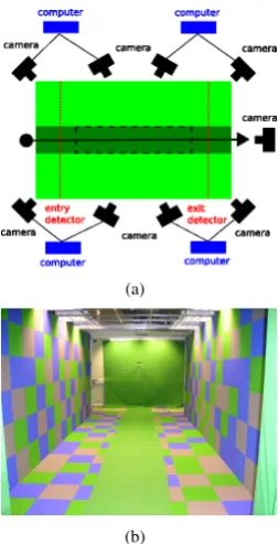
Fig. 2. The current tunnel (a) plan view (b) prototype
both clients of and service providers for other agents. Inter-agent communications are mediated by a common middleware. Additionally, locking mechanisms are provided to prevent multiple access to hardware devices such as cameras. The figure explicitly labels the various agents developed for the tunnel. Figure 2 shows the current tunnel prototype. It consists of a distributed array of 8 cameras, which are connected in pairs to local computers for efficient processing. Additional computers are used to control the entry and exit detection system and to coordinate the tunnel’s activities. The remainder of this section explains the various components of the tunnel.
A. Camera Calibration
As the tunnel will be performing 3D reconstruction upon the image data, camera calibration is essential. Calibration is the process of finding the camera model (K), pose (R), and position (t) of a camera. This information is used to project points in the world space,X= (X, Y, Z,1)T, to image coordinates,x= (x, y,1)T, as follows:
x=PX=K[R|t]X (1) Additionally, real camera lenses have imperfections which distort the image coordinates. The largest of these are due to radial distortion effects. Radial distortion is due to curvature of the lens as you move from the focal centre. After radial distortion the image coordinates become :
xd=xc+ (1 +κ1r+κ2r2+· · ·)x (2) Herexc is the lenses optical centre,ris the distance from the optical centre and κi are the radial distortion parameters. The camera is fully calibrated when K, R, K, and κi are
known. Typically these parameters are found via the use of a target with known geometric properties. The biometric tunnel, illustrated in figure 2(b), is used as the target for our calibration process. There are 4 steps to our calibration procedure : find radial distortion, find intrinsic parameters, find extrinsic parameters, and optimise over all cameras. These will now be briefly discussed.
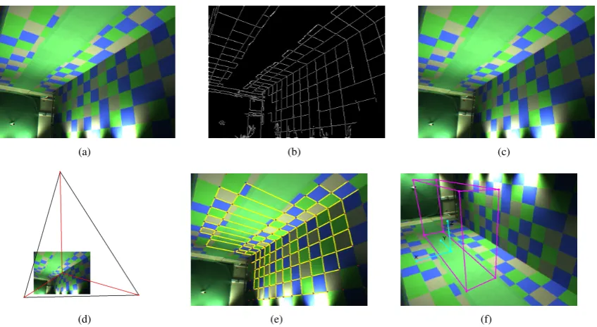
Figure 3(a) shows an image of the tunnel from one of the cameras. The edge information (figure 3(b)) computed via a Canny edge detector is then used to find the values of the radial distortion parameters. Specifically, it can be computed by finding the correction required to straighten long curves in the image. This is an ideal application for the Hough Transform [7] which is an efficient line finder. For a given edge image the image is radially corrected for different radial distortion parameters. Within each corrected image a score is assigned on the basis of the number of straight lines. These are accumulated for different sets of κi and the maximum is chosen. In our application we use two terms (κ1 andκ2) are sufficient to correct the image.
Starting with a radially corrected image the vanishing lines are used to estimate the intrinsic parameters of the camera. This method is similar to that of Cipolla [8] however we use an automated procedure to compute the vanishing lines. The Hough transform is employed to find the line segments in the edge image. By extending the segments to infinity the intersections of the lines can be found. These intersections are clustered into the 3 vanishing points using a weighted mean to ameliorate the effect of outliers. The orthocentre of the triangle created by linking the 3 vanishing points is then found. This is the centre of focus of the camera. From the orthocentre the focal scale factors can also be found. The orthocentre and focal scale factors together are the intrinsic parameters of the camera. These are illustrated in figure 3(d). Knowing that the top vanishing point corresponds to the z-axis and that the y-axis is aligned with the track the pose of the camera can be found. This leaves an ambiguity in the sign of x and y for the pose due to the fact that the camera could be inward or ourward facing. To solve this some knowledge about the environment is employed. It known that camera positions are are on the walls and looking towards the tunnels centre. By formingPfrom equation 1 using the possible values oft(the corners or centre of the walls) the sign ambiguity inRcan be found along with t. Thus, the extrinsic parameters have been found from the geometric properties of the environment.
(a) (b) (c)
[image:3.595.87.511.50.282.2](d) (e) (f)
Fig. 3. Steps in the calibration procedure (a) original image (b) edge detected image (c) radially corrected image (d) vanishing lines (e) world coordinates
overlaid on image (f) axes and volume of interest overlaid on image
metric. This means that measurements taken in the calibrated cameras will have a one to one relationship with measurements in the real world.
To implement the algorithm the gait camera agents were used to grab images and perform all the local calibration processes. The resulting parameters and the image data is then passed to another computer where the global optimisation is performed. Due to the distributed nature of this process it is very fast.
B. Person Detection
In order to detect an individual entering the tunnel, a simple detection system based upon break-beam detectors has been developed. One sensor is mounted at the entry and another at the exit of the tunnel as illustrated by dotted lines in figure 2(a). The detector units are interfaced to the parallel port as it conveniently provides inputs and outputs on the same connector. Pin 2 was used to reset the detector and Pin 11 was set low when a person enters the tunnel. A simple break beam detection agent was written to control the person detector. Internally it has two states. The first is the detector is off and the second is the system is primed and is actively polling. The state is toggled by setting the correct pins on the parallel port. If in the active state and the beam is broken a notification is sent to a controlling agent.
C. Background Subtraction
Removal of a subject from their background is a common computer vision process. The methodology used here is a small modification of a commonly employed technique [9]. While not as robust as other techniques [10] it is significantly faster. As a first step, an estimate of the background is needed. Normally the mean image is employed. However we use a
median image as it is more robust to slight variations in lighting. Furthermore, it can be computed in the presence of moving objects. This image is computed in RGB colour space. Once a background estimate is computed, removing the subject is a two step process: image differencing and shadow suppression. Image differencing allows most of the background pixels to be removed in a single pass leaving only the pixels that have changed from the background estimate. These remaining pixels are either the subject or artifacts due to lighting variations. In HSV space a shadow can be seen as a darkening of the value and a consequent decrease in saturation. This property is used to reclassify the candidate subject pixels as either background or foreground.
large which can cause network congestion problems.
D. Gait Reconstruction
As the cameras completely surround the subject a 3D recon-struction can be performed. Reconrecon-struction is achieved using a methodology known as voxel-based shape from silhouette [11]. The silhouette refers to the image of the person in the environment after background subtraction has been performed. Simply put the algorithm is a restatement of equation (1). For each camera view a 3D point or voxel, X, is projected to the camera coordinate system (x = PX). If X is found to be inside the silhouette in a sufficiently large (normally all) number of views then the voxel is a valid point in the original object. Whilst conceptually simple this algorithm is complex to perform in an efficient manner. This is due to the fact that for each voxel the projection needs to be performed for each of the cameras. For N voxels and C cameras this involves a maximum of N C matrix multiplications. The burden of computation can thus be reduced by precomputing image coordinates for each of the voxels. To further increase computation speed we perform two hierarchical passes of the voxel data. A low resolution pass to roughly localise the subject within a bounding volume and a high resolution pass performed within this volume. Whilst there is benefit to be had from a fully hierarchical approach such as octrees we found this two pass approach to be sufficient for this application.
As evidenced in the system overview (figure 1) the re-construction process requires data from gait camera agents. Specifically the subject silhouette from each of the cameras is required. This information is sent via the network to a central reconstruction agent. A point to note here is that even for small amounts of video data sent from each camera it becomes very easy to saturate the network card on the reconstruction computer. As an example, 8 cameras working at 30 fps with each supplying roughly one third of a640×480RGB image will result in 70 Mb/s of data sent to the network card. Thus it is impossible to reconstruct the data in real time with this sort of data rate. Instead we concentrate on servicing the incoming data so as not to saturate the card and then when all data is received perform the reconstruction. This results in a small delay of approximately the time the subject spends in the tunnel (3 s) before the reconstruction can be completed. For biometrics applications this is acceptable.
E. Face Detection
To detect the individual’s face in the tunnel, the end camera is employed (see figure 2(a)). This camera looks down the length of the tunnel and thus can capture clear views of the face for most of the tunnel. To help in this procedure a zoom lens is employed. This is adjusted to capture faces over a wide range of subject heights. The detection algorithm employs a multipass approach with several simple algorithms passed upon the incoming images. Firstly, background subtraction is performed. As there will only be one subject at a time in the tunnel the largest moving region corresponds to the subject. By employing the resulting silhouette as a mask the search space
can thus be reduced for subsequent algorithms. Finding the face is then relatively straightforward and employs a number of empirical algorithms. Firstly, the width of the silhouette is computed for the entire height. For an individual walking toward the camera there will be a large step change in the width at the point of the shoulders. Implementing this notion yields a revised estimate for the silhouette of just the head. The head is rejected if it doesn’t match known anatomical proportions for a head, or the size is incorrect (too small or too large), or the head is not in roughly the centre of the environment.
Implementation of this step is completely local and was implemented in a face camera agent. Potentially it could be a global process where the data from a background subtraction agent could be employed. However, resulting delay would be wasteful of network bandwidth and cpu cycles. Thus, the agent performs the processing steps outlined above in a hierarchical fashion to yield a face image.
III. RESULTS
While no large scale collection of data has yet been performed upon the biometric tunnel, we have performed sufficient experiments to demonstrate the tunnel’s capability. The test system consists of 8 cameras (640×480at 30 fps) for gait capture and a single high resolution camera (1024×768
at 30 fps) for face capture. The tunnel is a 5 m×3 m purpose built enclosure inside our laboratory.
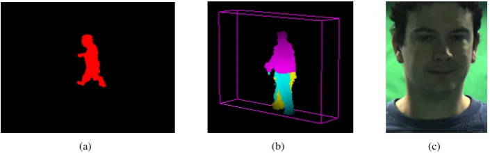
The first set of experiments test the functionality of the individual system components. The results for system cali-bration are shown in figures 3(e) and 3(f). The rectangular prism illustrates the common viewable area for all cameras. The world coordinate axes and origin as applied to the tunnel are also illustrated. Figure 4(a) shows a single frame from one camera upon which background subtraction has been performed. Full 3D reconstruction of the subject from all 8 cameras is illustrated for a single frame in figure 4(b). The physical size of the voxels in the person corresponds to 1cm3. The person is reconstructed inside a volume which corresponds to the prism in figure 3(f). Finally, figure 4(c) is a single frame from the face detection system.
In order to evaluate the performance of the system, timings were performed on the system’s bottlenecks. By doing this we can estimate the overall system performance and thus the physical throughput of the system. The results for each of the critical components to collect a single frame of data are:
component time (ms)
capture 33
background subtraction 270
transmission 12
reconstruction 250
face finding 385
save image 60
save voxel data 1300
(a) (b) (c)
Fig. 4. Example data available from biometric tunnel (a) background subtraction (b) 3D reconstruction (c) facial capture
(a) (b) (c)
0 0.2 0.4 0.6 0.8 1
0 20 40 60 80 100 120
value
frame
eye separation eye-mouth separation
[image:5.595.51.551.199.314.2](d)
Fig. 5. Finding extrema from a single frame (a) distance to perimeter (b) extrema found (c) trace of person in tunnel (d) extracted facial features
In all cases these figures are aggregate statistics gathered from approximately 100 trials. Clearly, it is not possible to perform real time processing of people using the current system. However, it will be possible to run close to real time. Assuming that a typical sequence consists of approximately 90 frames (3 seconds in tunnel) then further analysis can be performed. If processing is restricted to face alone the tunnel can process 52 people in an hour. Using gait alone, we can process 21 people an hour. Combined face and gait yields a throughput of 15 people an hour.
As the target application is biometrics, we examined fea-tures from the sequences and examined their performance on a small database of 6 people. This may seem small but is sufficient for the application of biometrics within a restricted environment such as a smart room or household. The features extracted were used to describe the face and gait of the individual.
In order to extract gait information a series of processes were carried out. For a single silhouette image the centroid (or average point), (cx, cy) was found. From this the Eu-clidean distance,d(i), from the centroid to the points on the perimeter was computed. Low pass filtering d(i) to produce
ˆ
d(i) suppresses noise in the silhouette (see figure 5(a). The local maxima ofdˆ(i)correspond to the head, feet, and hands of the subject (see figure 5(b)). Restricting ourselves to the leading leg and the head only we can reconstruct the 3D motion of these points. From the 3D data several metrics can be extracted. These include the bodies centroid (cx, cy, cz), the top of the head(hx, hy, hz), and the leading foot location
(lx, ly, lz).
In contrast to gait facial feature extraction is simple and
can be directly found from facial features. In this paper we extracted the eyes and the mouth from the face. The eyes are found using a circular Hough transform upon the edge detected facial image. The lips are localised using colour information. Using these features we extract two metrics : the inter-eye separation (see) and secondly the distance between the eyes and mouth (sem). As we are dealing with a sequence of face images with the subject approaching the camera the features need to be normalised by the face height, H, and width, W. Thus :
s0ee=see
W s
0
em=
sem
H (3)
Figure 5(c) show the derived metrics for an individual walking through the tunnel. The motion of each of the points con-forms closely to that measured from anatomical data [12]. Figure 5(d) shows the values of the face measures from a sequence of an individual in the tunnel. Notice that they are relatively linear and so should be sufficient for a simple recognition experiment.
(a)
[image:6.595.53.280.54.176.2](b)
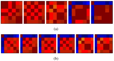
Fig. 6. Confusion matrix selecting (a) one feature (left to right : centroid,
head, leading foot, eye to eye distance, eye to mouth distance) (b) two features (left to right : centroid-eye to eye distance, head-eye to eye distance, foot-eye to eye distance, centroid-eye to mouth distance, head-eye to mouth distance, foot-eye to mouth distance).
individuals as evidenced by large blocks of the same colour. However, when used in pairs the population can easily be identified.
IV. DISCUSSION
The previous section demonstrated our biometric tunnel working on a variety of problems from background subtraction and 3D reconstruction to a simple biometric database. While the data is cropped and reduced in size in as many places as possible it is impossible to reduce the data any more without compromising information. The framerate cannot be reduced because this can result in blurring of gait and face which will result in erroneous features being extracted. For these reasons we have sacrificed system throughput in order to guarantee correctness of the information. This is an important distinction from tracking applications. It also demonstrates an important lesson about hierarchical processing. Now, while it would be possible to process all the information in a purely top down fashion there is benefit in not doing so. This is due to the fact that there are bottlenecks which would hold up the next processing step. Generally, it seems that the most efficient processing methodology, assuming complete data, is a mix of parallel and serial processing.
V. CONCLUSIONS
This paper discussed the development of a prototype metric tunnel. The purpose being to capture high quality bio-metric information from an individual as they interact with the environment. Consequently, the biometric tunnel shares much in common with tracking problems and smart environments. The proposed tunnel was designed to be deployed in a secure environment. Additionally, it potentially could be deployed in places such as border crossings or airports where biometrics are already being employed to help speed person authenti-cation. In the case of the tunnel, non-contact biometrics are captured to speed the processing of individuals. Specifically we designed the system to capture face and gait. Additionally, the tunnel is completely autonomous and requires no user intervention.
Our face capture system is designed to capture multiple snaps of the face. This is performed via a frontal face camera which is running continuously while a subject is in the environment. Processing is performed to select candidate faces from each frame. Additionally by extracting many faces the data is amenable to fusion. To describe gait we capture the subject from multiple views simultaneously and perform 3D reconstruction upon the resulting data. The resulting data is explicitly corrected for camera distortion and will provide a rich dataset for subsequent feature extraction.
The correctness of the system was demonstrated in the results section via the example outputs and the biometric example. The biometric example showed that the data gen-erated is sufficient to distinguish a small population such as a household. The current maximum throughput is approximately 15 people an hour. Roughly 50% of the time is currently spent writing the data onto the hard drive. This is an obvious area for improvement and is actively being explored currently. Currently, the data is stored with little or no contextual information. We are currently working on using semantic web technologies to provide this context via metadata and an ontology.
ACKNOWLEDGEMENT
The authors gratefully acknowledge support by the Defence Technology Centre 8-10 supported by General Dynamics, UK.
REFERENCES
[1] M. A. Turk and A. P. Pentland, “Face recognition using eigenfaces,”
in Proceedings IEEE Conference on Computer Vision and Pattern
Recognition, 1991, pp. 586–591.
[2] P. Viola and M. Jones, “Robust real-time face detection,” inProceedings
IEEE International Conference on Computer Vision, 2001, pp. 747–748.
[3] D. Cunado, M. S. Nixon, and J. N. Carter, “Automatic extraction and
description of human gait models for recognition purposes,”Computer
Vision and Image Understanding, vol. 90, no. 1, pp. 1–41, 2003.
[4] S. Sarkar, P. J. Phillips, Z. Liu, I. R. Vega, P. Grother, and K. W. Bowyer, “The humanid gait challenge problem: data sets, performance,
and analysis,” IEEE Transactions on Pattern Analysis and Machine
Intelligence, vol. 27, no. 2, pp. 162–177, 2005.
[5] D. Focken and R. Stiefelhagen, “Towards vision-based 3-d people
track-ing in a smart room,” inProceedings IEEE International Conference
Multimodal Interfaces, 2002, pp. 400–401.
[6] L. Middleton, S. Wong, M. O. Jewell, J. N. Carter, and M. S. Nixon, “A
middleware for a large array of cameras,” inProceedings of IEEE/RSJ
International Conf. on Intelligent Robots and Systems (IROS), 2005, pp.
3682–3687.
[7] M. Nixon and A. Aguado, Feature Extraction and Image Processing.
Newnes, 2002.
[8] R. Cipolla, T. Drummond, and D. Robertson, “Camera callibration from
vanishing points in images of architectural scenes,” in Proceedings
British Machine Vision Conference,, vol. 2, 1999, pp. 382–391.
[9] G. Cheung, T. Kanade, J. Bouquet, and M. Holler, “A real time system
for robust 3d voxel reconstruction of human motions,” inProceedings
of the IEEE Conference on Computer Vision and Pattern Recognition,
2000.
[10] C. Stauffer, “Adaptive background mixture models for real-time
track-ing,” inProceedings IEEE Conference on Computer Vision and Pattern
Recognition, 1999, pp. 246–252.
[11] N. Ahuja and J. Veenstra, “Generating octrees from object silhouettes
in orthographic views,” IEEE Transactions on Pattern Analysis and
Machine Intelligence, vol. 11, no. 2, pp. 137–149, 1989.
[12] J. Perry,Gait analysis : Normal and pathological function. SLACK