Dairy Automation Using Controlled Area Network Protocol
B.Praveen Kumar1, S.Rajagopal2
12Assistant Professor, Dept. of Electronics & Communication Engineering, Sri Aditya Engineering College, Surampalem
ABSTRACT
In these days automation in industry’s
increases rapidly. For safety purpose and to reduce man power requirement automation is adapted by industries. Some automation is fully automatic and some require human driver some control on automation. Automation has been achieved by various means including mechanical, hydraulic, pneumatic, electrical, electronic sensors, usually in combination. Complicated systems, such as, Milk Diaries, modern factories, airplanes and ships typically use all these combined techniques. These various sensor produced data collected by the vehicle data acquisition system by interactive communication through an intelligent information network called as Controlled area network (CAN). It is a serial bus protocol to connect control system to sensors as an alternative to conventional multi-wire looms. They currently use PLC based system in Milk industries of southern India which is costly and a lot of noise is induced in the system as the distance between the control room and the area of work is large. And for the flushing of milk containers they use manually operated system which is quite time consuming and always increases the man power. This paper analyses an Architecture of control system and deals with its application using the CAN Protocol. The benefits of this system over the system they currently employ is that noise reduction takes place as CAN
is used and it is much cost effective than the PLC’s
and the man power is reduced. This prototype system hardware circuits mainly consist of LPC2129 32-bit Microcontroller, MCP 2551 CAN standalone Controller, MCP 2515 Transceiver. LPC 2129 32 -bit Microcontroller which based on ARM 7 Advanced RISC Architecture CPU serially interfaced with MCP 2515 and CAN Controller Rx and Tx pin connected to Tx and Rx pin of MPC 2551 transceiver.
KEYWORDS:
CAN protocol, CAN bus, Data acquisition &control system, automation.
I. INTRODUCTION
The Controller Area Network (CAN) is a serial bus communications protocol developed by
Bosch in the early 1980s. It defines a standard for efficient and reliable communication between sensor, actuator, controller, and other nodes in real-time applications. The early CAN development was mainly supported by the vehicle industry: CAN is found in a variety of passenger cars, trucks, boats, spacecraft, and other types of vehicles. The protocol is also widely used today in industrial automation and other areas of networked embedded control, with applications in diverse products such as production machinery, medical equipment, building automation, weaving machines, and wheel chairs. Development and consequent implementation of controller area network (CAN) bus made revolutionary changes in the automotive industry design. Coupled with electronic rapid prototyping (ERP) hardware, it is possible to design, implement and test control algorithms of electronic control unit (ECU) on real-time controllers with real input/output devices. This new approach provides flexibility and speed when developing new features. This article describes one such example where experimental approach to teaching CAN bus based system was developed using an electronic rapid prototyping platform and CAN bus protocol to control a radiator system using sensors and actuators.
II. Controller Area Network (CAN) Protocol
reprogramming all the nodes to recognise the additional one. The additional node will, therefore, receive messages from the network and will decide whether to use or discard the received data.
Furthermore, each node is embedded with error detection, signalisation and self-checking features to ensure reliability. They are able to determine fault conditions occurring to the bus and transit to different modes according to the level of severity of the fault. Moreover, the CAN protocol provides nodes with sophisticated error detection and error handling mechanisms, such as cyclic redundancy check (CRC) with high immunity against electromagnetic interference. It has the capacity to differentiate between temporary errors and permanent failure of other nodes in order to modify their functionalities accordingly.
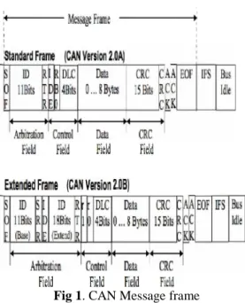
The first CAN protocol was defined by the ISO standard as a standard 11 bit identifier that provided signalling rates from 125 kbps to 1 Mbps with an identifier field that provided for 211 or 2,048 different messages identifiers known as version 2.0A. This version has later been upgraded to version 2.0B by extending the 11-bit identifier to 29-bit identifier with an identifier field that provides for 229or 537 million identifiers. Figure 1 illustrates both standards. The difference between both versions is that the extended version has a longer identifier length that the previous version as its identifier is made up of an 11-bit identifier plus an 18-bit extension identifier.
Fig 1. CAN Message frame
A bit-wise arbitration mechanism using identifiers is used to determine the priority of messages in order to avoid data collision, when all nodes are
sending data to the bus at the same time. 11 bits to 29 bits are the length usually associated with the identifier, while 0 to 8 bytes is the length given to the data. However, to support the non-destructive bitwise arbitration, two setups are required. The first setup is the use of logic states required to determine the nodes states, which can either be dominant or recessive. The second setup is that the node transmitting must monitor the bus state. This will enable to see if the logic state in the transmission process is currently appearing on the bus. In regard to CAN bus, the binary logic is used to determine the state of the node. The logic 0 represents the dominant bit while the logic 1 represents the recessive bit.
There are four types of frames used to constitute CAN, as follows:
J.
Data frame: contains node data for the transmission;K.
Remote frame: requesting data from a specific node;L.
Error frame: error detection ensured by a node within the bus;M.
Overload frame: resole delay between the data and/or the remote frame.The data frame is the most important field of CAN frames and consists of seven subcategories that are: star of frame, arbitration field, control field, data field, CRC field, ACK field, End of Frame. Figure 1 illustrates the data frame and the remote frame.
III. Control System using CAN
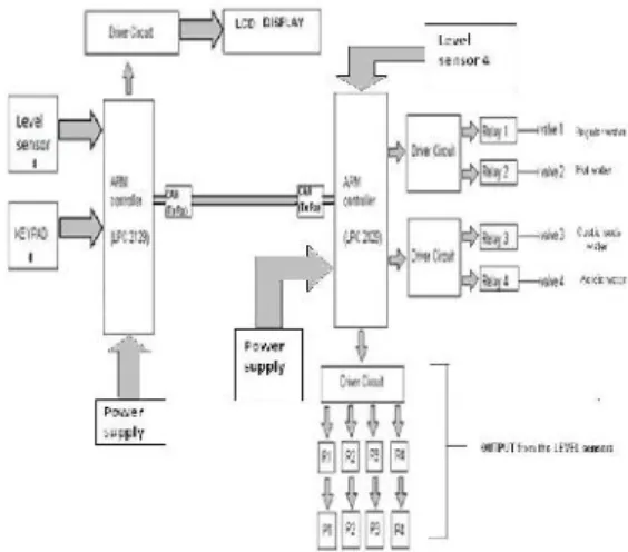
In our control system we are using CAN (controller area network) for the automation of the cleaning system. Our system will be containing two nodes. The first node is used for the decision making.
Fig 2. Block diagram of automated flushing
process
This methodology is better than the existing methodology as the cost of the system is much less as compared to the PLC based system. Noise produced in case of PLC is more, which in this system will be reduced to a great extent. It will also reduce the man power required for the cleaning of the milk containers as currently they have manually operated system for the container cleaning and we will provide automation for cleaning the containers too.
A. ARM Architecture:
ARM is a well-known microprocessor company, which designs a large number of high-performance, low-cost, low power consumption RISC processor, related technologies and software .The technology features high performance, low cost and power consumption. For a variety of areas, such as embedded control, multimedia, DSP and mobile applications, ARM architecture is the first RISC microprocessor designed for low-budget market. One of the typical products is ARM 7 family that is the most streamlined RISC. Therefore, it's relatively cheap, and the core of ARM7TDMI-S is a low budget- oriented, emphasizing the control of the system. It does not contain MMU (memory management unit). The embedded operating system will be subject to certain restrictions [4]. But because of its low price, reliability and other factors, it is widely used in various industrial controllers. For example MAC7100 microcontroller family is based on ARM7TDMI-S ™ 32-bit which is designed for embedded automotive applications development. In the MAC7100 series, the products contain multiple Flex CAN, enhanced serial communications peripheral device interface, which reduces system cost and improve the system's noise immunity [5].
B. CAN transceiver:
Typically, each node in a CAN system must have a device to convert the digital signals generated by a CAN controller to signals suitable for transmission over the bus cabling (differential output). It also provides a buffer between the CAN controller and the high-voltage spikes that can be generated on the CAN bus by outside sources
Receiving:
It adapts signal levels from the bus to levels that the CAN controller expects and has protective circuitry that protects the CAN controller.
Transmitting:
It converts the transmit-bit signal received from the CAN controller into a signal that is sent onto the bus.
IV. System Operation
The first node is used for the decision making. All sorts of decisions such as what process to select, real time signals, and transmitting the information to the second node that is the receiving node. The second is used for decision making as well as for monitoring the signals received from the first node. The second node drives the relay which will be used to drive the valves and pumps.
1. Level sensor: The level of the acid/water/caustic soda tank needs to be checked frequently so that it doesn’t get emptied or go below a particular level. So we are using level sensor or float sensor to detect the level of the fluid. And when the level of the fluid goes below a particular level it automatically gets filled from the reserve tank. 2. Real time clock: The two processes for flushing are:
i. Caustic soda method:
a. 10 Sec regular water
b. 5 Sec hot water
c. 25 Sec caustic soda
d. 5 Sec regular water
e. 25 Sec hot water ii. Acidic flushing method:
b. 10 Sec acidic flush
c. 5 Sec regular water
d. 10 Sec caustic soda
e. 5 Sec regular water f. 10 Sec hot water
3. Keypad: we are using keypad for selecting the appropriate process.
4. ARM LPC 2129: it consists of the CAN ports and hence we have used it in the project. It functions as the two nodes transmitting side and receiving side and each node have function as given below:
The first node is used for the decision making. All sorts of decisions such as what process to select, real time signals, and transmitting the information to the second node that is the receiving node
The second is used for decision making as well as for monitoring the signals received from the first node. The second node drives the relay which will be used to drive the valves and pumps.
5.
Driver Circuit: it is used for the interfacing between low voltage/current level circuitry and the high voltage/current level components like relay, pumps, lamp, valves, indicators etc. we are using ULN 2803 for driving the relay, pumps and valves.Required process of the automatic flushing
process:-1. Acidic process 2. Caustic soda process
Acidic Process: - Caustic Soda
Process:-5 sec. regular water 10 sec. regular water
↓ ↓
15 sec. caustic soda 5 sec. hot water
↓ ↓
10 sec. acid water wash 25 sec. caustic soda water
↓ ↓
5 sec. regular water wash 5 sec regular water wash
↓ ↓
10 sec. caustic soda wash 25 sec hot water wash
↓ ↓
5 sec regular water wash
↓
10 sec. hot water wash
↓ 5 sec. regular water wash
5 sec. regular water wash
V.
Conclusion
To overcome the limitations and the weakness of centralized control system, such as difficulties for system modification or extension, and wiring and installation cost, serial communication systems known as CAN-protocol based systems have been developed. This paper presents a brief overview of CAN protocol network. This network is gaining high ground in many applications from automobile industry to automation and factory industries.
CAN is a multi-master serial bus that allows an efficient transmission of data between different nodes. With its flexibility and robustness against electrical interference and also Digital control on the CAN Nodes is an important criterion industrial automation. In this paper, the CAN-bus based automation and control system for milk industry is designed. Which is low cost, high reliability and other features to meet the needs of the modern automobile industry.
REFERENCES:
[1] Robert Bosch GmbH, “CAN Specification”, Version 2.0,
[2] Pazul, K. Controller Area Network (CAN) Basics, Microchip Technology Inc,
[3] Review of Researches in Controller Area Networks Evolution and Applications Wei Lun Ng *, Chee Kyun Ng, Borhanuddin Mohd. Ali, Nor Kamariah Noordin, and Fakhrul Zaman Rokhani
[4]Zhang, Q.S., et al., Application of Embedded Technology for Induced Polarization Instrument. Advanced Materials Research, 2012. 383: p. 224-229.
[5] Prodanov, W., M. Valle, and R. Buzas, A controller area network bus transceiver behavioral model for network design and simulation.IEEE
Caustic Soda
Process:-10 sec. regular water
↓
5 sec. hot water
↓
25 sec. caustic soda water
↓
5 sec regular water wash
↓
25 sec hot water wash
↓
Transactions on Industrial Electronics, 2009. 56(9): p. 3762-3771
[6] Li, S., et al., Continuous and Real-Time Data Acquisition Embedded System for EAST. IEEE Transactions on Nuclear Science,, 2010.57(2): p. 696-698
B.Praveen Kumar, M.Tech with specialization in Embedded Systems is working in Sri Aditya Engineering College as Assistant Professor in E.C.E Department.