Int. J. Electrochem. Sci., 6 (2011) 6607 - 6619
International Journal of
ELECTROCHEMICAL
SCIENCE
www.electrochemsci.org
Preparation and Characterization of Ruo
2Catalysts for Oxygen
Evolution in a Solid Polymer Electrolyte
J. C. Cruz 1, V. Baglio2, S. Siracusano 2, V. Antonucci 2, A. S. Aricò 2, R. Ornelas 3, L. Ortiz-Frade 1, G. Osorio-Monreal1, S. M. Durón-Torres 4, L.G. Arriaga 1*
1 Centro de Investigación y Desarrollo Tecnológico en Electroquímica S.C., Parque Tecnológico
Querétaro, Sanfandila Pedro Escobedo, C.P. 76703, Querétaro, México.
2
CNR-ITAE, Via Salita S. Lucia sopra Contesse 5-98126 Messina, Italy
3
Tozzi Renewable Energy SpA, Via Zuccherificio, 10-48010 Mezzano (RA), Italy
4
UACQ – UAZ, CU Siglo XXI Edificio b, Km 6 Carr. Zac – Gdl, La Escondida Zacatecas, Zac, C.P. 96160, México.
*
E-mail: [email protected]
Received: 5 July 2011 / Accepted: 9 November 2011 / Published: 1 December 2011
RuO2 electrocatalysts were synthesized and characterized for the oxygen evolution reaction in a Solid
Polymer Electrolyte (SPE) electrolyzer. The catalysts were prepared by a colloidal preparation procedure and thermal treatment at different temperatures from 200 to 350 ºC. The material characterization was carried out by XRD, TG-DSC and TEM analyses. The RuO2 catalysts were
sprayed onto a Nafion 115 membrane with a loading of 3 mg cm-2. A Pt catalyst was used at the cathode compartment with a loading of 0.6 mg cm-2. The electrochemical activity of MEAs was investigated in a single SPE cell and in a conventional three-electrode half-cell by using linear voltammetry, impedance spectroscopy and chronoamperometry. The maximum current density at high potential (1.8 V) was obtained for RuO2 calcined at 300°C for 1 h. The chronoamperometric
measurements shown that the most stable catalyst was the RuO2 calcined at 300°C for 3 h.
Keywords: Water Electrolysis; RuO2 catalyst; SPE electrolyzer
1. INTRODUCTION
first electrolyzers using a polymer membrane as electrolyte were developed by General Electric Co. in 1996 for space applications [2].
The oxygen evolution reaction (OER) occurs at a suitable reaction rate on noble metal electrodes (e.g., Pt, Au, Ir, Rh, Ru, and Ag); however, metal oxides are generally more active electrocatalysts for this reaction than metal electrodes [3-5]. The most active oxides for the OER are RuO2 and IrO2 [6-14]. IrO2 exhibits high corrosion– resistance properties, but slightly lower activity
than RuO2 [15]. From the point of view of electro-catalysis, it is important to consider the crystal-field
stabilization energy, the dispersion, the crystallinity, and the crystallite size of these oxides. RuOx is
generally prepared by thermal decomposition of RuCl3 [16], which is applied as thin coating on a
metallic substrate, usually titanium. The properties of the oxide layer depend on several factors: technique of applying the salt solution, concentration of solution, temperature of calcination, time of heating, etc.
Various methods were developed for the synthesis of noble metals based oxides [17, 18], i.e. the Adams fusion method [19], sol-gel methods [20-24], polyol methods [9, 25]. The different methodologies can affect the properties of the obtained oxide materials.
Furthermore, various steps are necessary to complete the oxide powder synthesis. In the present study, a simple, fast and low cost method of preparation of a RuO2 electro-catalyst, compared to the
literature [26-28], was used.
A similar procedure was developed by Zheng et al. [29] for electrochemical capacitor applications; yet, in that case, the particle size was about 20 nm. This synthesis allowed us to obtain a crystalline phase with a suitable particle size (about 10 nm) at low temperatures with a yield of 95%. As reported by H. Ma et al. [28], particle sizes and heat treatment of the material influence the catalytic performance of RuO2 for OER and the stability. Calcined RuO2 with large particle sizes showed higher
corrosion resistance than uncalcined and low-temperature treated materials [28]. For this reason, in the present study, the synthesized RuO2 was subjected to different calcination temperatures and
investigated in half-cell and single-cell experiments.
2. EXPERIMENTAL
2.1 Preparation of RuO2 electrocatalysts
0.01 mol of RuCl3•3H2O (Aldrich) was dissolved in 100 mL of deionized water. The aqueous
2.2 Physico-chemical characterization
XRD was performed on the dry electrocatalytic powders using a Philips X-Pert diffractometer that used as radiation source the Kα line of the copper (CuKα). The diffractometer was operated at 40 kV and 20 mA, a step time of 0.5 2 min-1, and an angular resolution of 0.005° 2. The diffraction patterns were fitted to JCPDS (Joint Committee on Powder Diffraction Standards) and crystalline size distribution was calculated using LBA (line broadening analysis). The TG/DSC analysis was carried out in an STA 409C of NETZSCH - Gerätebau GmbH Thermal Analysis. The sample was heated from room temperature up to 550 °C at a heating rate of 5 °C/min under air atmosphere.
The morphology of catalysts was investigated by transmission electron microscopy (TEM) using a Philips CM12 instrument. Specimens were prepared by ultrasonic dispersion of the catalysts in isopropyl alcohol depositing a drop of suspension on a carbon-coated grid.
2.3 Preparation of working electrode for half-cell measurements
An aqueous solution (100 µl) of catalyst (5 mg) was prepared and mixed in an ultrasonic bath. 2 µl of aqueous solution of catalyst was deposited on a glassy carbon substrate; afterwards, the electrode was coated with 1 µl of Nafion® solution (5% Aldrich). The behaviour of the various catalysts for oxygen evolution reaction was investigated by linear voltammetry (LV).
2.4 Half-cell electrochemical characterization
The electrochemical analyses were carried out at room temperature in a conventional three-electrode cell consisting of the ruthenium oxide three-electrode (working three-electrode), a reference three-electrode (Hg/HgSO4 sat.) and a platinum grid (counter electrode). The electrolyte solution was 0.1 M H2SO4.
An inert gas was fed to the solution for 30 min before the test. The cell was connected to an AUTOLAB PGSTAT 302 Metrohm potentiostat/galvanostat. To evaluate catalysts activity for OER, a linear voltammetry in a potential range from 1.20 V to 1.65 V vs. RHE was carried out.
2.5 Preparation of membrane and electrode assembly (MEA)
A Nafion 115 (Ion Power) membrane was used as solid polymer electrolyte. The oxygen evolution catalysts were directly deposited onto one side of the Nafion 115 by spray technique. Catalytic inks were composed of aqueous dispersions of catalyst, deionised water, Nafion® solution (5% Aldrich) and anhydrous Ethylic alcohol (Carlo Erba); the anode catalyst loading was about 3 mg cm-2. A Ti/Pt (95:5) grid was used as backing layer. A commercial 30% Pt/Vulcan XC-72 (E-TEK, PEMEAS, Boston, USA) was used as catalyst for the H2 evolution. The cathode electrode was
layer after drying. MEAs were directly prepared in the cell housing by tightening at 9 N•m using a dynamometric wrench.
2.6 Electrochemical characterization of MEA
The SPE electrolyzer performance was evaluated in a temperature range from 25 to 80°C. Heated deionised water, which was circulated by a pump at a flow rate of 2 ml/min, was supplied to the anode compartment. The water temperature was maintained at the same cell temperature. Measurements of cell potential as a function of current density, electrochemical impedance spectroscopy (EIS) and chrono-amperometry were carried out by using an Autolab PGSTAT 302 Potentiostat/Galvanostat equipped with a 20 A booster (Metrohm).
3. RESULTS AND DISCUSSION
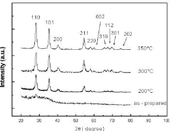
XRD analyses were carried out on the anode catalysts. Figure 1 shows XRD patterns of the precursor powder before and after calcination at 200, 300 and 350°C.
Figure 1. X-Ray diffraction patterns of RuO2 as-prepared and calcined powders at various
temperatures.
The XRD peaks were assigned to RuO2 in a tetragonal crystallographic structure. No presence
[image:4.596.125.478.394.665.2]
main peaks by the Debye-Scherrer equation. The crystallite size found was in an interval from 8 to 12 nm and it was similar for the powders calcined at the different temperatures. In order to investigate the precursor calcination process, a thermal analysis was carried out. The results of TGA and DSC measurements are shown in Figure 2.
Figure 2. TGA and DSC curves of RuOx as-prepared powder.
The first weight loss was assigned to physical dehydration (below 120°C); whereas, the second one was attributed to chemical dehydration (in the range 120-210°C). An endothermic peak was observed in the range 180-260°C due to an amorphous to crystalline structure phase transition of RuO2
as confirmed by XRD. Above 260°C a slight oxygen loss was recorded. Total weight losses of 14 wt.% were observed after treatment at 550°C.
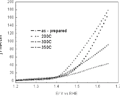
Figure 3 shows the half-cell I-V curves for uncalcined and calcined samples. The best performance for the oxygen evolution reaction at ambient temperature was obtained for the RuO2
powder calcinated at 300°C. The maximum current density was 180 mA cm-2
at 1.65 V. This catalyst was selected for the further investigations in an SPE electrolyzer. In order to evaluate the effect of duration of the thermal treatment, a RuO2 calcined at 300°C for 3 h was also prepared for comparison.
[image:5.596.98.502.168.445.2]
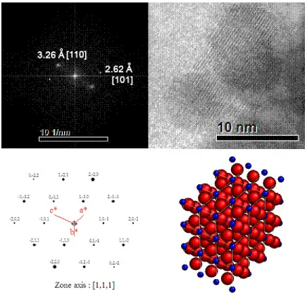
image by Fourier transformations and using Carine crystallography software allowed to confirm the tetragonal crystal phase of RuO2; a scheme representation of the crystal structure is presented in figure
6. The powder calcined for 3 h showed a similar morphology of the sample calcined for 1 h (not shown).
Figure 3. Linear Voltammetry of RuO2 powder-based electrodes, synthesized and calcined at various
temperatures, in 0.5 M H2SO4 half – cell at 25°C.
[image:6.596.105.506.160.482.2]
[image:7.596.156.420.71.278.2]
C
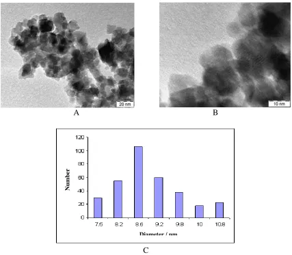
Figure 4. TEM micrographs of RuOx synthesized: (A) and (B) at different magnifications (C) Particle
size distribution analysis.
A B
C
Figure 5. TEM micrographs of RuO2 calcined at 300 °C/1 h: (A) and (B) at different magnifications
(C) Particle size distribution analysis.
Num
b
er
Diameter / nm
Num
b
er
[image:7.596.85.512.342.715.2]
Figure 6. TEM image of RuO2 calcined at 300 °C/1 h: Scheme representation of tetragonal RuO2
crystal structure by Carine Crystallography Software
The three samples were analyzed in a SPE single cell electrolyzer. Series and charge transfer resistances were evaluated by means of EIS at 1.5 V. Figure 7 shows the EIS spectra of electrolyzers with the above mentioned catalysts at 80°C under atmospheric pressure. The impedance plots (Nyquist) reveal a larger series and charge transfer resistance for the amorphous RuO2 than the
calcined ones. The minimum in the series resistance was observed for the electrolyzer with the powder calcined at 300°C for 1h with a value of 0.19 ohm•cm2
; whereas, the lowest charge transfer resistance was obtained for the sample calcined for 3 h, i.e. 0.085 ohm•cm2
.
[image:8.596.80.516.68.506.2]
MEA electrodes. A contribution of sulfate anions adsorption in determining a poorer performance on half cell experiments is not discarded.
0.0 0.5 1.0 1.5 2.0 2.5 3.0
0.0 0.5 1.0 1.5 2.0 2.5 3.0
as - prepared 300 °C 1h 300 °C 3h
-Z i
/
c
m
2
Zr / cm2
0.20 0.24 0.28 0.32
0.00 0.05 0.10
Synthesized 300°C 1hr 300°C 3hrs
-Z
i
/
c
m
2
Zr / cm2
Figure 7. Impedance Spectroscopy of the SPE electrolyzer based on RuO2 electrocatalysts,
as-prepared and calcined at 300°C for 1 h and 3 h at 80°C and 1.5 V.
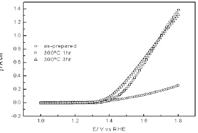
Figure 8. Linear Voltammetry of the SPE electrolyzer based on RuO2 powders, as-prepared and
[image:9.596.122.473.135.377.2] [image:9.596.105.503.458.726.2]
Figure 9. Tafel plot for oxygen evolution reaction in a SPE electrolyser for the RuO2 powder calcined
at 300°C for 1 h and 3 h at 80°C.
The cell equipped with RuO2 calcined at 300°C for 3 h showed an onset for the OER more
shifted towards lower potentials according to the lower charge transfer resistance obtained by the EIS analysis. This indicates a better catalytic activity of this catalyst probably due to a suitable crystalline structure. The cell based on RuO2 calcined at 300°C for 1 h showed a higher onset potential for OER
than the previous one, but a better behavior in terms of ohmic characteristics, according to a lower series resistance recorded by EIS analysis for this cell. Thus, the maximum current density at high potential (1.8 V) was obtained using RuO2 calcined at 300°C for 1 h; it was about 1.4 A cm-2.
This performance appears to be comparable to the state of art [30-34] in this field and it appears promising if one considers that a simple catalyst preparation method, which can be subjected to further improvement, was used.
The ohmic-drop-corrected Tafel plots for oxygen evolution reaction at the RuO2
electrocatalysts calcined at 300°C for 1 h and 3 h are shown in Figure 9. Two Tafel slopes have been identified for the oxygen evolution process at 80°C in the PEM electrolyser. At low current densities, the Tafel slope is 65-75 mV•dec-1, whereas at large current densities it is 132-133 mV•dec-1. These values are similar to those already observed in the literature at room temperature for the oxygen evolution process with oxide based electrodes [15, 35-38]; i. e., 60 mV•dec-1 and 120 mV•dec-1 in the low and high current density range respectively.
A Tafel slope of 120 mV•dec-1
S + H2O → S – OH + H+ + e- (1)
The low Tafel slope can be attributed to the presence of adsorption intermediates involving OH species on the electrode surface with different energy states [15, 35]. It is not discarded a possible contribution to the rate determining step of the electrochemical desorption of a proton from the adsorbed OH species as reaction intermediates at low current densities.
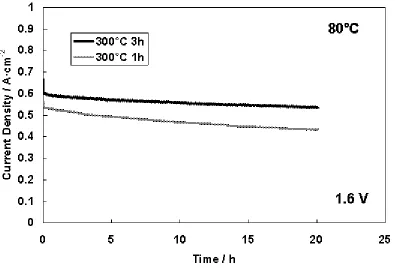
Figure 10. Chronoamperometric measurement of the SPE electrolyser based on RuO2 calcined at
300°C for 1 h and 3 h at 80°C
Figure 10 shows the chronoamperometric measurements carried out at 80°C and atmospheric pressure for the RuO2 electrocatalysts calcined at 300°C for 1 h and 3 h. These experiments were
performed at a potential of 1.6 V for 20 hours. The cell equipped with RuO2 calcined at 300°C for 3 h
showed a higher current density compared to the cell equipped with RuO2 calcined at 300°C for 1 h.
This evidence was in agreement with the I-E curves (Fig. 8). It was observed that the current density slightly decreased during the time for both measurements. This could be due to the presence of small particles in the catalysts that can be more subjected to corrosion; on the contrary of large RuO2
particles which appear to be sufficiently stable [28]. However, our evidences confirm the low stability of RuO2 that was discussed in several papers in the literature [12, 13]. The largest loss was showed
with RuO2 calcined at 300°C for 1 h. This could be due to the higher stability of RuO2 particles
calcined for 3 h compared to RuO2 particles calcined for 1 h. However, an increase of the RuO2
[image:11.596.105.500.201.469.2]
strategy to improve the stability of the RuO2 electrocatalyst relies on the use of IrO2-RuO2 solid
solutions. The aim is to reach a good compromise between stability and performance.
4. CONCLUSIONS
A simple, fast and low temperature colloidal method for the obtainment of RuO2 nano-particles
was developed. Catalysts were prepared by colloidal deposition at a temperature near to 100°C and, successively, calcined at different temperatures from 200 to 350ºC. The physico-chemical characterization was carried out by XRD, TG-DSC and TEM analyses. The electrochemical activity of these catalysts as anodes in an SPE electrolyzer was investigated. The maximum current density at high potential (1.8 V) was obtained using RuO2 calcined at 300°C for 1 h; it was about 1.4 A cm-2.
Yet, the best results were obtained for the RuO2 calcined at 300°C for 3 h in the chronoamperometric
measurements with a higher current density at 1.6 V for 20 hours compared to the RuO2 calcined at
300°C for 1 h. However, chronoamperometric measurements showed a slightly decrease of performances with time. A further optimization of the physico-chemical proprieties of these materials is necessary in order to increase the stability and performance for application in a PEM electrolyzer.
ACKNOWLEDGMENTS
The authors acknowledge Tozzi Renewable Energy S.p.A. for the financial support. J.C. Cruz, L.G. Arriaga and S.M. Durón thank the Mexican Council for Science and Technology (Conacyt, Fomix-Zacatecas 81728) for financial support.
References
1. R. Oberlin, M. Fischer, Brown Boveri Review, 73(1986) 445-450. 2. W. Kreuter, H. Hofmann, Hydrogen Energy Progress XI, 1 (1996) 37-48.
3. V. Baglio, A. Di Blasi , V. Denaro T, Antonucci, AS Aricò, R. Ornelas, F. Matteucci , G. Alonso, L. Morales , G. Orozco, L.G. Arriaga, J. New Materials for Electrochem. Systems, 11(2008) 105-108.
4. L.G. Arriaga, W.M . Martínez, U. Cano, H. Blud, Int. J. Hydrogen Energy, 32(2007)2247-2252. 5. A.Marshall, B. Børresen, G. Hagen, M. Tsypkin, R. Tunold , Mater Chem Phys, 94(2005)
226-232.
6. L.M. Da Silva, J.F.C. Boodts, L.A. De Faria, Electrochim. Acta, 46(2001)1369-1375. 7. H. Tamura, C. Iwakura, Int. J. Hydrogen Energy, 7 (1982)857-865.
8. S. Trasatti, G. Lodi, Part B. Elsevier, Amsterdam, 1980.
9. E. Rasten, G. Hagen ,R. Tunold, Electrochim. Acta, 48 (2003)3945-3952.
10.A.De Oliveira-Sousa, M.A.S. Da Silva, S.S. Machad, l.A. Avaca, P. De Lima-Neto, Electrochim. Acta, 45 (2000) 4467-4473.
11.T. Ioroi , N. Kitazawa, K. Yasuda, Y. Yamamoto, H. Takenaka, J. Electrochem. Soc., 147 (2000)2018-2022.
12.R. Kotz, H.J. Lewerenz, S. Stucki, J. Electrochem. Soc., 130 (1983)825-829. 13.R. Kotz, S. Stucki, Electrochim. Acta, 31(1986)1311-1316.
15.J.M. Hu, J.Q. Zhang, C.N. Cao, Int. J. Hydrogen Energy, 29(2004)791-797. 16.Y. Zhang, C. Wang, N. Wan, Z. Mao, Int. J. Hydrogen Energy, 32 (2007)400-404. 17.J.R. Osman, J.A. Crayston, A. Pratt, D.T. Richens, Materials Chemistry and Physics,110
(2008)256-262.
18.Q.L. Fang, D.A. Evans, S.L. Roberson, J.P Zheng, J. Electrochem. Soc., 148 (2001) A833-837. 19.R. Adams, R. Shrine, J. Am. Chem. Soc., 45 (1923) 2171-2179.
20.Y. Murakami, H. Ohkawauchi, M. Ito, K. Yahikozawa, Y. Takasu , Electrochim. Acta, 39 (1994)2551-2554.
21.Y. Murakami, S. Tsuchiya , K. Yahikozawa, Y. Takasu, Electrochim. Acta, 39(1994)651-654. 22.M. Ito, Y. -Murakami, H. Kaji, H. Ohawauchi, K. Yahikozawa, Y. Takasu , J. Electrochem. Soc.,
141(1994)1242-1245.
23.K. Kameyama, S. Shohji, S. Onoue, K. Nishimura,K. Yahikozawa, Y. Takasu, J. Electrochem. Soc., 140(1993)1036-1037.
24.T. Lassali, J. Boodts, L. Bulhoes, J. Non-Cryst. Solids, 273(2000)129-134.
25.F. Bonet, V. Delmas, S. Grugeon, R. Herrera-Urbina, P. Silvert, K. Tekaia-Elhsissen, Nano Struct. Mater., 11(1999)1277-1284.
26.M. Lopez, A. Schleunung, P. Biberbach, Patent n° WO2005049199.
27.C. Urgeghe C, PhD thesis on “Oxygen Evolution and Oxygen Reduction in Electrochemical Energy”, University of Ferrara, Italy, 2005.
28.H. Ma, C. Liu, J. Liao, Y. Su, X. Xue, W. Xing, Journal of Molecular Catalysis A: Chemical, 247(2006)7-13.
29.P. Zheng, P.J. Cygan, T.R. Jow TR, J. Electrochem. Soc., 142(1995)2699-2703.
30.S. Song, H. Zhang, X. Ma, Z. Shao, R.T. Baker, B. Yi, Int. J. Hydrogen Energy, 8( 2008)4955-4961.
31.L. Krusin-Elbaum, M. Wittmer, J. Electrochem. Soc., 135(1988)2610-2614.
32.L. Nanni, S. Polizzi, A. Benedetti, A. De Battisti , J. Electrochem. Soc., 146(1999)220-225. 33.M. Ito, Y. Murakami, H. Kaji, K. Yahikozawa, Y. Takasu Y, J. Electrochem. Soc.,
143(1996)32-36.
34.A.S. Aricò, V. Antonucci, V. Alderucci, E. Modica, N. Giordan, .J. Appl. Electrochem., 23(1993)1107-1116.
35.Z.G. Ye, H.M. Meng, D. Chen, H.Y. Yu, Z.S. Huan ZS, X.D. Wang, D.B. Sun, Solid State Sciences, 10(2008)346-354.
36.A.Damjanovic, A. Dey, J.O.M. Bockris, J. Electrochim. Acta, 11(1966)791-814. 37.R. Mraz, J. Krysa, J. Appl. Electrochem., 24(1994)1262-1266.
38.S. Jin, S. Ye, Electrochim. Acta, 41(1996)827-834.