www.geosci-instrum-method-data-syst.net/2/323/2013/ doi:10.5194/gi-2-323-2013
© Author(s) 2013. CC Attribution 3.0 License.
Instrumentation
Methods and
Data Systems
Enhanced timing accuracy for Cluster data
K. H. Yearby, S. N. Walker, and M. A. Balikhin
University of Sheffield, Department of Automatic Control and Systems Engineering, Mappin Street, Sheffield, S1 3JD, UK
Correspondence to: K. H. Yearby ([email protected])
Received: 14 June 2013 – Published in Geosci. Instrum. Method. Data Syst. Discuss.: 9 August 2013 Revised: 20 November 2013 – Accepted: 21 November 2013 – Published: 19 December 2013
Abstract. The standard timing accuracy for the Cluster mis-sion is±2 ms. However for inter-spacecraft comparisons of waveform data, a much higher accuracy is needed – for ex-ample a timing error of 1 ms results in a phase error of 65◦ for a signal at 180 Hz. Most Cluster data are recorded on an onboard solid state recorder and time-stamped using an onboard clock which is calibrated to coordinated universal time (UTC). Until recently, the error of this onboard clock was allowed to increase to the±2 ms limit before a new cal-ibration was applied. However, the timing error for real-time data is estimated to be only∼11 µs, so these data may be used to prepare a time correction data set which allows the standard timing accuracy to be improved considerably. This paper describes the details of the preparation and validation of this data set. Two independent source data sets are used: telemetry to European Space Agency (ESA) ground stations supporting the main operations of the Cluster spacecraft, and the real-time telemetry to the NASA Deep Space Network (DSN) stations supporting the Wide-Band Plasma Wave In-vestigation.
1 Introduction
The Spatio-Temporal Analysis of Field Fluctuations (STAFF) and Electric Field and Wave (EFW) experiments, forming part of the Wave Experiment Consortium (WEC) on the Cluster spacecraft, include magnetic and electric field waveform data at frequencies up to 180 Hz in the high bit rate mode (Cornilleau-Wehrlin et al., 199; Gustafsson et al., 1997; Pedersen et al., 1997). Inter-spacecraft comparison of these data, for example to estimate wave properties by
k filtering or phase differencing, requires better than the standard 2 ms timing accuracy.
The timing accuracy required is discussed by Pincon and Motschmann (1998), and a series of simulations performed by Pincon and Lefeuvre (1992). These suggest the phase er-ror should ideally be less than 5◦, and that the fit with the model becomes very poor for an error of 30◦or above. At a frequency of 180 Hz, these phase errors correspond to a tim-ing accuracy of 77 µs, and 460 µs respectively.
An alternative estimate of the timing accuracy required may be derived from the propagation speed of the waves and the accuracy of the spacecraft position. For example a whistler mode wave in the magnetosheath with a frequency of 150 Hz propagates at around 3×10⁶ms−1. The maximum error in the spacecraft position is 5 km, so the timing error should be much less than 1.67 ms to avoid contributing to errors in the estimated wave properties. Timing accuracy is more important at small spacecraft separations as coherence between the measurements is maintained at higher frequen-cies.
The Wide-Band Data (WBD) Plasma Wave Investigation (Gurnett et al., 1997) measures waves up to 577 kHz. At these frequencies (above the local plasma frequency) waves can propagate at close to the velocity of light (3×10⁸ms−1), so a timing accuracy better than 15 µs is ideally needed.
This need for high timing accuracy was recognised during the proposal phase of the Cluster mission, but not accepted by the agency as a formal requirement. Instead the guaran-teed timing accuracy was 2 ms, but with an expectation that considerably better accuracy could be achieved in practice. In the worst case, a 2 ms accuracy corresponds to a 4 ms er-ror between spacecraft, which is 260◦of phase at 180 Hz. In
the normal bit rate, for which the maximum signal frequency is 10 Hz, the maximum phase error would be 12◦.
from the spacecraft in real time, but are recorded on an on-board solid state recorder. All data released to experimenters (both recorded on board and acquired in real time) are time-stamped using an onboard time (OBT), which is calibrated to UTC using a time correlation process.
Experiment data are not time-stamped directly. Timing is coordinated by means of a reference pulse distributed to the experiments by the spacecraft onboard data handling system (OBDH). It is the responsibility of each experiment to de-termine the time of data sampling relative to this reference pulse and include this information as part of the experiment data. Each packet of experiment data acquired by the OBDH is then stamped with the time of the reference pulse.
Until recently, the error between OBT and UTC was al-lowed to increase to the±2 ms limit before a new calibration was applied. This typically occurred around once per month. The time correlation process uses the real-time data, which are time-stamped by the ground stations with the Earth re-ceive time. By subtracting various delays, including the prop-agation time from spacecraft to ground, the spacecraft event time (SCET) is obtained. The total error for real-time data is estimated to be∼11 µs, determined by adding various er-ror sources, the main contributions being uncertainty in the spacecraft position and ground station clock drift (ESOC re-port CL-ESC-TN-0006, personal communication, 1992).
During each real-time pass, the difference (DIFF) between the SCET measured by the onboard clock and that derived from the Earth receive time is monitored. When the differ-ence exceeded 2 ms, a new time correlation was performed. This process is described in detail in the European Space Op-erations Centre (ESOC) report CL-OPS-TN-1004-OPS-OPC provided to the authors as a private communication, but this should be available from the Cluster Science Archive in due course.
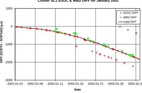
The DIFF measurements can be used to apply a correction to the onboard clock to bring its accuracy close to that of the real-time data. The DIFF is slowly varying, so a simple lin-ear interpolation can be used to estimate the DIFF between real-time passes. An independent set of DIFF measurements are also available during real-time data acquisition for the WBD experiment from the ground stations of the NASA Deep Space Network (DSN) and Panska Ves. An example of the variation in the DIFF parameter is shown in Fig. 1.
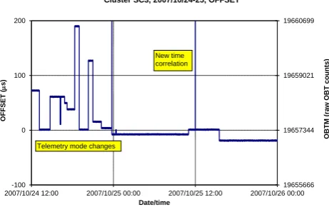
Detailed analysis of the time stamps has revealed that a second correction is needed. When data are recorded on board, the OBT recorded in the data packets is not precisely correlated with the timing reference pulse distributed to the experiments but may be subject to an offset which is fixed for each period of the same telemetry mode. This term is called OFFSET and specifies the difference between the time of the reference pulse and the OBT recorded in the data pack-ets. It applies only to data recorded on board, and is zero for real-time data. OFFSET normally ranges±180 µs for normal mode data, and±30 µs in burst modes.
-3000 -2000 -1000 0 1000
2002-01-01 2002-01-06 2002-01-11 2002-01-16 2002-01-21 2002-01-26 2002-01-31
D
IF
F
[SC
ET
rt
-
SC
ET
o
b
t]
(
m
s)
Date
Cluster SC1 ESOC & WBD DIFF for January 2002
[image:2.595.312.542.67.217.2]ESOC DIFF WBD DIFF Valid DIFF
Fig. 1. Plot of the DIFF values measured by ESOC (+)and WBD
(×). The solid line represents the assumed correct value used to pre-pare the time corrections. The “DIFF” (the difference between the ground receive time and the onboard time) is measured during every ground station contact. However some measurements are subject to errors, so a validation process must be applied.
The DIFF and OFFSET parameters together form the Time Correction (TCOR) data set produced by the Digital Wave Processor (DWP) team and available from the Cluster Science Archive (CSA) (Yearby et al., 2010; Woolliscroft et al., 1997).
From 23 November 2007, a new time correlation pro-cedure has been adopted at ESOC. A time correlation is now performed during every nominal pass, instead of wait-ing until the DIFF reaches 2 ms. As a result the value of DIFF is usually less than 20 µs, but this is not guaranteed. While a correction for the OFFSET term is in principle still needed, for burst mode data (when the most accurate timing is needed), this is less than 30 µs, so without correction the overall timing will usually be accurate to±50 µs. This corre-sponds to 100 µs between spacecraft, which is sufficient for STAFF and EFW data up to 180 Hz. However, it will still be possible to use the time correction data set when the highest possible accuracy is needed.
2 Production
2.1 DIFF pre-November 2007
-200 0 200 400 600 800
2008/08/01 2008/08/11 2008/08/21 2008/08/31 2008/09/10 2008/09/20 2008/09/30
D
IF
F
(
m
s)
Date
Recalibrated ESOC and WBD DIFF measurements, Cluster C2, 2008
[image:3.595.311.546.62.340.2]ESOC DIFF ESOC DIFF (recal.) WBD DIFF (recal.)
Fig. 2. Recalibrated DIFF measurements after November 2007.
When time calibrations are performed every pass, the DIFF values are small and give no indication of the long-term behaviour of the onboard clock. The recalibrated DIFF has a parabolic form similar to that seen in Fig. 1.
To obtain DIFF between measurements, a linear interpola-tion is normally used.
2.2 DIFF post-November 2007
Since 23 November 2007, a time calibration has been per-formed during every nominal pass. This process resets the DIFF to zero, so the trends shown in Fig. 1 are no longer seen, and it is difficult to validate the data directly. Instead the DIFF is recalibrated relative to virtual time calibrations performed every 30 days. This allows any discontinuities to be easily seen (Fig. 2). This recalibrated DIFF is used only for validation purposes.
2.3 WBD DIFF
[image:3.595.51.276.77.231.2]The DIFF values are calculated using the OBT and ground receive time fields in the WBD “level 1” data released by the University of Iowa. The values are then compared against a linear interpolation between the two nearest ESOC DIFF measurements. The difference between the WBD DIFF and interpolated ESOC DIFF is termed “delta”. Typical results are shown in Fig. 3a, and are normally in the range 0 to 50 µs. However, when the data are plotted against the ground station antenna number, as shown in Fig. 3b, then we see that each antenna has a range of delta values covering only 20 µs. The mean offset for each antenna can be subtracted to give recali-brated WBD DIFF values with a mean as close as possible to the ESOC ones. In practice, just three separate offset values are used: one for antenna 46, one antennae 80 and 81, and one for all others. In each case the same offset values apply to all Cluster spacecraft.
Fig. 3. Comparison of DIFF measured during WBD (DSN/Panska
Ves) and ESOC ground station contacts. WBD-ESOC DIFF versus date shows a bias, usually small and positive (a). Plotting the same data versus antenna ID shows antennae 46, 80 and 81 have a differ-ent bias to the others (b). Data for antenna 80, near the end of June, are anomalous due to a timing problem at the Panska Ves station.
2.4 OFFSET
The OFFSET term is determined by the DWP team by anal-ysis of the time stamps of the housekeeping telemetry. The OBT is maintained by counting the cycles of a 220Hz clock. The count is padded on the right-hand side with four zero bits to form the 56 bit OBT value. Taken as a whole this count represents the cycles of a virtual 224Hz clock. This raw OBT value is not included in the data released to experimenters. Rather, it is converted to UTC by applying the current time calibration. The first stage of the OFFSET analysis is to ob-tain (approximately) the raw OBT by inverting the time cali-bration.
there must be a variable offset between the time at which the reference pulse is issued and the OBT recorded in the data. We assume that this offset is zero for retime data, al-though any constant value, the same for all spacecraft, would not affect inter-spacecraft timing accuracy. The deviation of OBTM from the real-time value is the OFFSET parameter.
A difficulty arises when there is a change in the regular occurrence of the timing reference pulse. Small changes of 122 µs (2048 OBT counts) sometimes occur when the OBDH mode changes. This is first apparent when the OBTM during a period of real-time telemetry differs from that seen pre-viously. It is then necessary to determine when the change occurred. This is done by analysing the times of indepen-dent regular events measured relative to the reference pulse. Two independent events are currently used: the internal mas-ter clock pulse of the WEC and the Sun reference pulse.
Finally, the DIFF and OFFSET values are merged to form the TCOR data set, which is available from the Clus-ter Science Archive (CSA). This data set has a pair of records for each period of constant OFFSET. Linear in-terpolation of the original DIFF values is used to obtain values at the times of OFFSET changes. The CSA may be accessed at http://www.rssd.esa.int/index.php?project= CLUSTER&page=Access_to_CSA.
3 Validation
Whilst the time correction process seems straightforward, there are a number of difficulties that can arise even after the initial DIFF measurements have been validated.
3.1 Validity of original OBT–UTC calibration
The initial time calibration is performed by ESOC and recorded in the TCAL files that are included with the exper-iment raw data. Experexper-imenters do not usually need to refer to these files as the calibrations are already applied. They are however essential for the purpose of making enhanced accu-racy timing as the corrections applied are relative to the orig-inal calibration. Initially this caused a difficulty, as prior to November 2007 the period to which each calibration applied was not known precisely. This occurred because whenever a new calibration was determined it was applied to all data re-ceived on the ground from that point onwards, including data that may have been acquired on board up to 2 days before when a previous calibration was still active.
Use of the wrong time calibration becomes apparent dur-ing the process of estimatdur-ing the OFFSET parameter. Instead of the quantity OBTM being constant with step changes, it shows a continuous linear change. Such data are rejected dur-ing processdur-ing, and are the main reason for the periods where time corrections are not available during this early part of the mission.
After November 2007 the process at ESOC was changed so time calibrations were applied strictly according to their period of validity using the time that data were originally acquired on board.
3.2 Interruptions to the onboard clock
Onboard anomalies can cause a switchover from the main to the redundant data handling system, or an eclipse can cause the loss of all power on the spacecraft (there is now little or no battery capacity left). Such events cause an interruption to the onboard clock requiring a completely new time cali-bration. Furthermore, after such an event it may take several days for the stability of the clock to return to normal. This means the normal linear interpolation of DIFF values may be impossible to perform or have reduced accuracy.
3.3 Changes to the reference pulse timing
As noted in Sect. 2.4 above, changes may occur in the regular occurrence of the timing reference pulse. We attempt to iden-tify these by reference to two independent regular events: the internal master clock pulse of the WEC experiment and the Sun reference pulse. Neither method is completely satisfac-tory.
The WEC master clock is 900 Hz and derived from a basic crystal oscillator with a stability of about 1 part in 106. The time of the clock pulses is measured using a software timer. This is normally done on every timing reference pulse (ev-ery 5.152222 s) and has an accuracy of a few microseconds. Sometimes however the measurement is interrupted by other processes, so it is not available. This can make it difficult to identify exactly when any change in the reference pulse tim-ing has occurred.
The Sun reference pulse is generated when the spacecraft spin brings the Sun sensor in alignment with the Sun direc-tion. This process is normally remarkably stable in the short term (to within a few microseconds in the 4 s spin) but is upset following a manoeuvre when oscillations in the spin period can continue for several hours. The Sun reference pulse is currently used during the production process, with the WEC master clock used for validation.
19655666 19657344 19659021 19660699
-100 0 100 200
2007/10/24 12:00 2007/10/25 00:00 2007/10/25 12:00 2007/10/26 00:00
OB
T
M
(r
aw
OB
T
co
u
n
ts)
OF
F
SET
(
m
s)
Date/time
Cluster SC3, 2007/10/24-25, OFFSET
New time correlation
[image:5.595.51.282.67.212.2]Telemetry mode changes
Fig. 4. OFFSET specifies the difference between the time of the
ref-erence pulse (VC0 reset pulse) and the onboard time stamp recorded in the data packets. It applies only to data recorded on board, changes at every telemetry mode change, and is zero for real-time data. OFFSET normally ranges±180 µs for normal mode data, and ±30 µs in burst modes. It is derived from analysis of the raw on-board time modulo 42 207×211(termed OBTM).
4 Caveats
Users of the TCOR data set should be aware of its limita-tions. Most importantly, time corrections are not available at all times. Coverage is typically around 90 %. Applications re-quiring accurate timing should confirm that TCOR data are available at the relevant time.
Time corrections are provided at the start and end of each segment (a time interval with no telemetry mode changes). These segments have a duration from a minimum of one minute to a maximum of about 27 h (half an orbit). Time cor-rections at other times may be obtained by interpolation sub-ject to certain rules. The OFFSET term is constant through-out each segment. When the OFFSET values before and after the required time are different, then OFFSET is not available at that time. No interpolation between different OFFSET val-ues is allowed. The DIFF may be obtained by linear interpo-lation of the DIFF values at the beginning and end of the current segment.
5 Application
For WEC data, the time corrections may be applied using the latest version of the Telemetry Extraction and Decom-mutation (TED) sofware package (see Yearby et al., 2010). This is done automatically once TED and the TCOR files are correctly installed. By default, TED 2.5 produces de-commutated science data files with all time corrections ap-plied. A new bit in the packet header diagnostic word (HKT-COR_CORRECTED) will be set when time corrections have been successfully applied. This bit should be checked by ap-plications requiring accurate timing.
0.049 0.050 0.051 0.052 0.053 0.054
00:00 04:00 08:00 12:00 16:00 20:00
A
d
ju
sted
W
EC
ti
me
(s)
Time (UTC)
Cluster SC1 WEC time, 2004-03-25
Corrected Uncorrected
TDA mode 4 to 6
New time correlation
TDA mode 9H to 4
Fig. 5. Final validation of time corrections. The chart shows WEC
data time stamps modulo 0.1 s, and are adjusted for the average rate of drift of the WEC clock. The uncorrected time shows jumps due to the change in OFFSET at telemetry data acquisition (TDA) mode changes, and due to change in DIFF at a new time correlation. These jumps are removed when the corrections are applied.
The result of applying time corrections is illustrated in Fig. 5. The uncorrected time shows jumps due to the change in OFFSET at telemetry data acquisition (TDA) mode changes, and due to change in DIFF at a new time cor-relation. These jumps are removed when the corrections are applied.
It is also possible to apply time corrections to the raw telemetry data or to calibrated high-level science data, pro-vided that microsecond level precision is maintained during the processing of the data. The basic method is to obtain the DIFF and OFFSET at the required time, and add these to the data time tag.
The TCOR data set is applicable to all data acquired from the Cluster spacecraft via ESA ground stations. The TCOR data set itself is generally not used for creation of the epoch variable in the WBD CDF/CEF data files archived at the CSA. This is because WBD data acquired via DSN or Pan-ska Ves ground stations already have sufficient timing accu-racy. However, on rare occasions the TCOR production pro-cess identifies apparent errors in the time calibration of these ground stations. For these cases, the WBD team will use the TCOR data set to correct the onboard time supplied in the WBD transfer frame to obtain the epoch variable. The timing accuracy in these cases will be comparable to that attainable via DSN or Panska Ves ground stations.
6 Conclusions
[image:5.595.311.545.67.230.2]to the order of 20 µs by applying corrections from the TCOR data set in the Cluster Science Archive.
For future missions, the required timing accuracy should, if possible, be accepted as a formal specification. If this is not practical, then procedures should be adopted to get the best accuracy reasonably achievable rather than just meet-ing the specification. The change in procedure at ESOC from November 2007 (a new time correlation during every nom-inal pass) dramatically improved the basic timing accuracy achieved from 2 ms to around 50 µs.
Acknowledgements. The authors thank colleagues at ESOC and
the University of Iowa for providing the source data for the time correction data set. The current work and the Cluster mission were funded by the European Space Agency.
Edited by: C.-P. Escoubet
References
Cornilleau-Wehrlin, N., Chauveau, P., Louis, S., Meyer, A., Nappa, J. M., Perraut, S., Rezeau, L., Robert, P., Roux, A., de Villedary, C., de Conchy Y., Friel, L., Harvey, C. C., Hubert, D., Lacombe, C., Manning, R., Wouters, F., Lefeuvre, F., Parrot, M., Pinçon, J. L., Poirier, B., Kofman, W., and Louarn, Ph.: The CLUSTER Spatio-Temporal Analysis of Field Fluctuations (STAFF) Exper-iment, Space Sci. Rev., 79, 107–136, 1997.
Gurnett, D. A., Huff, R. L., and Kirchner, D. L.: The wide-band plasma wave investigation, Space Sci. Rev., 79, 195–208, 1997. Gustafsson, G., Bostrom, R., Holback, B., Holmgren, G., Lundgren,
A., Stasiewicz, K., Ahlen, L., Mozer, F. S., Pankow, D., Harvey, P., Berg, P., Ulrich, R., Pedersen, A., Schmidt, R., Butler, A., Fransen, A. W. C., Klinge, D., Thomsen, M., Falthammar, C. G., Lindqvist, P. A., Christenson, S., Holtet, J., Lybekk, B., Sten, T. A., Tanskanen, P., Lappalainen, K., and Wygant, J.: The electric field and wave experiment for the Cluster mission, Space Sci. Rev., 79, 137–156, 1997.
Pedersen, A., Cornilleau-Wehrlin, N., de la Porte, B., Roux, A., Bouabdellah, A., Décréau, P. M. E., Lefeuvre, F., Sené, F. X., Gurnett, D., Huff, R., Gustafsson, G., Holmgren, G., Woollis-croft, L. J. C., Thompson, J. A., and Davies, P. H. N.: The Wave Experiment Consortium (WEC), Space Sci. Rev., 79, 93–106, 1997.
Pincon, J.-L. and Lefeuvre, F., The application of the generalized Capon method to the analysis of a turbulent field in space plasma: experimental constraints, J. Atmos. Terr. Phys., 54, 1237–1247, 1992.
Pincon, J.-L. and Motschmann, U.: Multi-Spacecraft Filtering: General Framework, in: Analysis Methods for Multi-Spacecraft Data, Paschmann G. and Daly, P. W., ESA Publications Division, Noordwijk, the Netherlands, 65–78, 1998.
Woolliscroft, L. J. C., Alleyne, H. St. C., Dunford, C. M., Sumner, A., Thompson, J. A., Walker, S. N., Yearby, K. H., Buckley, A., Chapman, S., Gough, M. P., and the DWP Co-investigators: The digital wave processing experiment on Cluster, Space Sci. Rev., 79, 209–231, 1997.