A Prospective Analysis of
INTRAMEDULLARY FIXATION OF UNSTABLE
PERITROCHANTERIC FRACTURES WITH INTERLOCKING
PROXIMAL FEMORAL NAIL
Dissertation submitted to
THE TAMILNADU DR.M.G.R. MEDICAL UNIVERSITY
Chennai.
With fulfillment of the regulations
for the award of the degree of
MS (ORTHOPAEDIC SURGERY)
BRANCH – II
KILPAUK MEDICAL COLLEGE
CHENNAI
CERTIFICATE
This is to certify that this dissertation on “PROSPECTIVE ANALYSIS OF INTRAMEDULLARY FIXATION OF UNSTABLE PERITROCHANTERIC FRACTURES WITH INTERLOCKING
PROXIMAL FEMORAL NAIL” is a bonafide work done by Dr. S.
ALFRED SATHIYA SEKAR, Post Graduate, Department of
Orthopaedic Surgery, Government Royapettah Hospital, Kilpauk Medical College, Chennai, under my guidance and supervision in partial fulfillment of the regulations of The Tamilnadu Dr. M.G.R. Medical University, Chennai for the award of M.S. Degree in Orthopedic Surgery (Branch – II) during the academic period - 2004-2007.
Prof. Dr. A. SIVA KUMAR M.S. (Ortho)., D.Ortho.,
Professor and Head of Department, Department of Orthopaedics, Govt. Royapettah Hospital & Kilpauk Medical College, Chennai – 10.
Prof. Dr. K. NAGAPPAN,
M.S. (Ortho)., D.Ortho., Professor of Orthopaedics, Govt. Royapettah Hospital & Kilpauk Medical College, Chennai – 10.
Prof. Dr. A. THIAGAVALLI KIRUBAKARAN, M.D.
THE DEAN
Government Kilpauk Medical College Chennai.
I declare that this dissertation entitled “PROSPECTIVE ANALYSIS OF INTRAMEDULLARY FIXATION OF UNSTABLE PERITROCHANTERIC FRACTURES WITH INTERLOCKING
PROXIMAL FEMORAL NAIL” has been conducted by me at
Department of Orthopaedic Surgery, Govt. Royapettah Hospital, Kilpauk Medical College Chennai-10, under the guidance and supervision of my Chief Prof. Dr. K. NAGAPPAN, M.S. (Ortho)., D.Ortho.,
Govt. Royapettah Hospital and Kilpauk Medical College Chennai. It is submitted in part of fulfillment of the award of the degree of M.S (Ortho) for the March 2007 examination to be held under the Tamil Nadu Dr. M.G.R Medical University, Chennai. This has not been submitted previously by me for the award of any degree or diploma from any other university.
ACKNOWLEDGEMENT
I deem it as a pleasure and privilege to express my utmost
gratitude to Prof. Dr. A. THIAGAVALLI KIRUBAKARAN, M.D., Dean,
Kilpauk Medical College for providing me an opportunity to conduct
this study using the facilities to the full extent.
I wish to dedicate my whole hearted thanks and gratitude to my
beloved, kind hearted and caring Chief Prof. Dr.K. NAGAPPAN,
M.S.(Ortho)., D.Ortho., Professor of Orthopaedics, Government
Royapettah Hospital, Kilpauk Medical College, Chennai for his
valuable suggestions, unique guidance and constant encouragement
throughout the study.
I express my sincere thanks and gratitude to a very kind,
encouraging and caring head of the department of Orthopaedics
Prof. Dr. A. SIVAKUMAR, M.S.(Ortho), D.Ortho., Professor and Head of
Dept. of Orthopaedics, Government Royapettah Hospital, Kilpauk
Medical College, Chennai, for his invaluable help and guidance.
I express my heartfelt gratitude to my Assistant Professor and
guide Dr. S. SENTHIL KUMAR, M.S. (Ortho)., D. Ortho., who had
My sincere and special thanks to my
Assistant Professors Dr. N. O. SAMSON, M.S.(Ortho)., D.Ortho.,
Dr. S. ANBAZAHAGAN, M.S.(Ortho), D. Ortho., DNB Ortho., and
Dr. G. LEONARD PONRAJ, M.S.(Ortho)., D. Ortho., M.Ch. Ortho.,who were
very helpful and supportive right throughout my study.
I wish to express my thanks to my Post graduate colleagues,
Anesthesiologist, staff members of other department and our theatre
staff for the help they have rendered.
Finally, though last but not the least, I thank all my patients
who gave full co-operation with commitment and made this study
CONTENTS
1. INTRODUCTION 1
2. AIM OF THE STUDY 5
3. ANATOMY – PROXIMAL FEMUR 6
4. APPLIED ANATOMY 9
♦ PROXIMAL FEMUR
♦ NECK SHAFT ANGLE
♦ FEMORAL ANTEVERSION
♦ TRABECULAR PATTERN
♦ CROSS SECTIONAL ANALYSIS
♦ SOFT TISSUE AROUND HIP
♦ VASCULAR SUPPLY
5. BIO MECHANICS 20
6. MECHANISM OF INJURY 25
7. SIGNS AND SYMPTOMS 26
8. RADIOGRAPHIC AND IMAGING STUDIES 27
9. CLASSIFICATION 28
10. HISTORICAL REVIEW 32
11. POST-OP CARE 43
12. COMPLICATIONS 45
13. MATERIALS AND METHODS 49
14. SURGICAL TECHNIQUES 55
15. RESULTS 59
16. CASE ILLUSTRATION 64
17. DISCUSSION 65
18. CONCLUSION 70
19. ANNEXURE 72
♦ PROFORMA
♦ HARRIS HIP SCORE
♦ MASTER CHART
INTRODUCTION
Fractures around the trochanteric region of femur are one of the
commonest fractures encountered in orthopaedics and also the most
devastating injuries of the elderly. The incidence of this fracture
increases with advancing age. These patients are more limited to
home ambulation and are dependent in basic and instrumental
activities of daily living. Growing number of population and the road
traffic accidents have resulted in an enormous increase in these type
of fractures. In younger patients the fractures usually result from
high energy trauma like RTA and fall from height and accounts for
only ten percent .Older patients suffering from a minor fall can
sustain fracture in this area because of weakened bone due to
osteoporosis or pathological fracture and this accounts for 90%.
Since the femur is the longest and the strongest bone in the
body and one of the principal load bearing bone in the lower extremity
fracture of this bone may result in prolonged morbidity and extensive
disability unless the treatment is appropriate. These fractures are
associated with substantial morbidity and mortality. Approximately
15 to 20% patients die within one year of fracture. After one year
patients appear to resume their age – adjusted mortality rate. Until
of fractures in the form of traction with prolonged bed rest with
fracture healing occurring in ten to twelve weeks (usually) followed by
a lengthy programme of ambulation training. These are associated
with complications of prolonged recumbence like decubitus ulcer, UTI,
joint contractures, pneumonia and thrombo- embolic complications
resulting in high mortality rate.
During this century a better understanding of the biomechanics
of the fracture and the development of better implants have lead to
radical changes in treatment modalities. Increasing emphasis on the
preservation of blood supply to the fracture fragments and autogenous
bone grafting has improved biological results. While the development
in biomedical research have yielded implants of greater strength and
longer fatigue life. With the thorough understanding of fracture
geometry and biomechanics optimal treatment can be selected for
individual cases.
After 1960’s the first successful implants were fixed angle - nail
plate devices like Jewett and Holt nail which provided stabilization of
femoral head and neck fragment to the femoral shaft but failed to
provide controlled impaction. This gave rise to sliding – nail plate
devices like Massie nail and Ken-Pugh nail which provided both. Then
modification of this resulted in the introduction of sliding hip screws
screw with a large outside thread diameter to improve proximal
fragment fixation and decrease the risk of screw cutout by eliminating
sharp edges. Then the concept of bidirectional sliding came into play
by the introduction of Egger’s plate and Medoff plate. The sliding hip
screw device with its modification has been used widely and
successfully for more than a decade for the treatment of these
fractures.
In unstable trochanteric fractures where there is loss of
postero-medial cortex continuity, when load is applied increased bending force
on the DHS lead to implant breakage, screw cutout or separation of
plate from shaft. This lead to the introduction of Intramedullary
devices which theoretically due to its position provides more efficient
load transfer and shorter lever arm can decrease tensile strain
thereby decreasing the risk of implant failure. Though Zickel
introduced his nail long ago it was not very popular due to higher
incidence of complications, so was the case with ender’s nail. Zickel
nail was later modified and renewed interest is being given to intra
medullary fixation with devices like the IMHS (intra medullary hip
screw), Gamma nail, Russell – Taylor reconstruction nail, ATN ( Ante
grade trochanteric nail), TFN (Trochanter fixation nail) and the PFN
less blood loss, better biomechanical stability and earlier mobilization
provided by this devices.
In 1997, PFN (Proximal femoral nail) was introduced in
Czechoslovakia by Synthes company which has the biomechanical
advantage of all IM devices and considered to be as a second
generation nail. Several recent studies are going on for comparison
with DHS and other IM devices and the results are encouraging but
PFN
AIM OF THE STUDY
To assess the effectiveness of Intramedullary fixation of
unstable peritrochanteric fractures with interlocking proximal
FIG 1
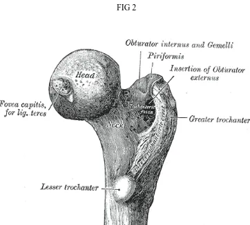
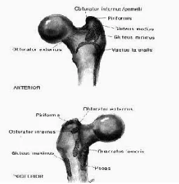
[image:14.612.159.468.99.328.2] [image:14.612.130.492.351.677.2]ANATOMY
The proximal femur Head
The head of the femur is capped with hyaline cartilage and is
more than half a sphere. The medial convexity has a pit, the “Fovea”
entered for the ligament of teres. Anteriorly the articular cartilage
extends on the neck for weight bearing in the flexed hip. (Fig – 1)
Neck
The neck of the femur is an upward extension of shaft
strengthened internally by the calcar femorale. The neck joins the
greater trochanter in front along a rough ridge, the inter-trochanteric
line. The back of the neck joins the greater trochanter at a prominent
rounded ridge, the inter-trochanteric crest. The neck of the femur is
inclined at an angle with the shaft. This angle is about 160◦ in young
children and about 125◦ in adults with an ante version of 15◦ in
adults.
Greater trochanter
The GT of the femur is a large, irregular, quadrilateral
the shaft. It is directed a little lateral and backward and in the adult
is about 1cm lower than the head. (Fig 2) It has two surfaces (medial & lateral ) and four borders ( superior, inferior , anterior & posterior
).
Lateral surface : serves for the insertion of the tendon of the
gluteus medius.
The medial surface : the trochanteric fossa (digital fossa), for
the insertion of the tendon of the Obturator externus, and the
insertion of the Obturator internus and Gemelli.
The superior border : insertion of the Pyriformis.
The inferior border : gives origin to the upper part of the Vastus
lateralis.
The anterior border : at its lateral part insertion to the Gluteus
minimus.
The posterior border : bounds the back part of the trochanteric
fossa.
The Lesser Trochanter (small trochanter) of the femur is a
conical eminence. From its apex three well-marked borders extend;
FIG3
of these are above—a medial continuous with the lower border of the
neck, a lateral with the intertrochanteric crest; the inferior border is
continuous with the middle division of the linea aspera (Fig 3). The summit of the trochanter is rough, and gives insertion to the tendon of
the Psoas major.
Proximal Shaft (Fig 4)
1. Trochanteric fossa
2. Greater trochanter
3. Quadrate tubercle
4. Inter – trochanteric crest
5. Gluteal tuberosity
6. Linea aspera
7. Fovea for ligamentum teres attachment
8. Lesser trochanter
APPLIED ANATOMY
Proximal femur
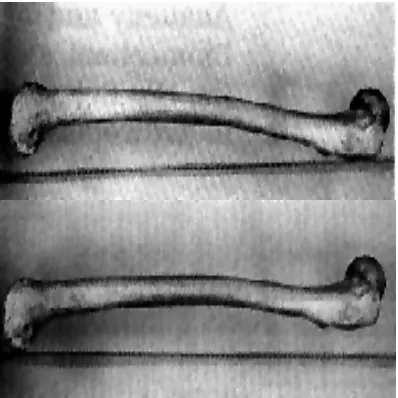
The form of the femur is relatively complex, with bows and
twists that distort its basically tubular structure. The anterior bow of
the midportion of the femur is well recognized and has even been built
into some current prostheses. This is commonly envisioned as an
anterior bow because of the position that the separate femur assumes
when it is placed on a horizontal surface, resting on the posterior
margin of the trochanter and the posterior aspects of the condyle (Fig 5).
However, in vivo the orientation is somewhat different. In the
erect position, the central portion of the femur is more in the coronal
plane of the body, with the distal portion inclined posteriorly to the
knee and the proximal portion inclined anteriorly to the acetabulum
(Fig 6).
The posterior bow of the proximal femur is just as constant as
the midportion anterior bow. The central portion of the proximal
posterior bow is opposite the level of the lesser trochanter. This bow is
FIG 5 FIG 6
FIG 7 FIG8
[image:21.612.104.276.506.659.2]The Neck-Shaft Angle
The head of the femur considerably overhangs the femoral shaft.
This occurs because the neck makes an oblique angle with the shaft of
an average of 135°. Although there is considerable variability in both
the neck-shaft angle and neck length, in general the center of the
femoral head is extended medially and proximally by the femoral neck
so that the center of the femoral head is at the level of the tip of the
trochanter. The effect of the overhanging head and neck is to
lateralize the abductors, which attach to the greater trochanter, from
the center of rotation (center of the femoral head). This increases the
torque generated by the abductors and reduces the overall force
necessary to balance the pelvis during single leg stance. Reducing this
level arm (coxa valga) increases total load across the hip, and coxa
vara reduces it to the extent it increases the lever arm. (Coxa vara
with a short neck would have a negative affect.)
Femoral Anteversion
The coronal plane of the femur is generally referenced to the
posterior distal femoral condyles. When oriented in this plane, it can
be seen that the proximal femur, including the femoral head and neck,
are rotated anteriorly. This is commonly referred to as femoral
Distribution of Cancellous Bone in the Proximal Femur
A critical look at a good quality anteroposterior (A-P) x-ray of
the femur gives a good idea of the distribution of cancellous bone in
the femur. It appears to be a characteristic of the articulating ends of
long bones that the broad ends, covered with articular cartilage, are
supported principally by cancellous bone and a very rudimentary
cortex in the form of a subchondral plate. The forces applied to the
articular surfaces are carried by the cancellous bone out to the cortex.
It does not appear to be a coincidence that where the cortex reaches
its full thickness, the cancellous bone essentially stops.
The distribution of cancellous bone that is suggested in the
x-ray is vividly illustrated in the coronal cut through a desiccated femur
(Fig 8).
Trabecular pattern: The upper end of femur consists of five trabecular groups, they are (Fig 9 & 10).
A. Principal Compressive Group – It is the upward projection of the calcar femorale to the weight bearing superior dome of head
of femur.
FIG 9 FIG 10
[image:24.612.136.491.415.673.2]
arches across the superior region and terminates in the lateral
cortex.
C. Greater Trochanter Group – Seen in the region of greater trochanter.
D. Secondary Compressive Group – Seen between the two
primary groups.
E. Secondary Tensile Group – Also seen between the two
primary groups.
The primary compression and primary tensile trabeculae enable
the proximal femur to withstand considerable tensile and compressive
forces to which it is normally subjected. In the greater trochanter a
gothic arch is formed by the intersection of arcuate bundle and
trochanteric bundle. Head and neck also contains gothic arch by the
intersection of arcuate bundle and supporting bundle. At the point of
intersection the bone is denser and constitutes the nucleus of the
head.
There are two areas of paucity of trabeculae - the Babcock
triangle situated in the inferior aspect of the head , the ward’s triangle
situated lateral to primary compression trabeculae and below tension
in the causation of femoral neck fractures in the elderly. They offer
less rigid fixation to any implant in this area. It also offers little
resistance to shearing forces in fracture neck of femur even after
fixation of the fracture.
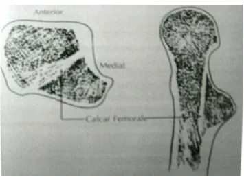
Calcar femorale:
It is a dense vertical plate of bone extending from the postero
medial portion of the femoral shaft under the lesser trochanter and
radiating later to the greater trochanter reinforcing the femoral neck
postero-inferiorly. It is thickest medially and gradually thins as it
passes laterally (Fig 11).
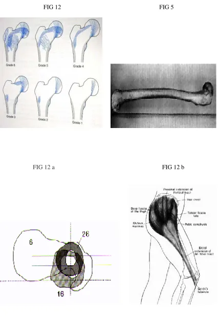
Singh’s index for osteoporosis:
Grades osteopenia based on the reduction in trochanteric,
tensile and ultimately primary compressive trabeculae. The grade is
determined from the AP projection of an intact proximal femur (Fig – 12).
Normal – (grade 6 : all trabecular groups are visible ) to
FIG 12 FIG 5
FIG 12 a FIG 12 b
Cross – sectional analysis:
On the lateral view, the posterior bow of the proximal femur can
be seen with its apex opposite the lesser trochanter (Fig-5). The three aspects of the anatomy of the femur that limit the access of stems that
are straight in the lateral plane are the posterior margin of the
femoral neck, the anterior margin of the cortex opposite the lesser
trochanter, which represents the apex of the posterior bow of the
femur, and the posterior cortex of the shaft where the bow of the
femur is reversing into an anterior bow. The straight stem would bind proximally at the posterior margin of the neck, in the mid-portion at
the anterior cortex, and distally at the posterior cortex. A larger stem
prosthesis would have the tendency to blow out the posterior neck as
the stem follows the anterior bow of the midfemur or to punch through
the posterior cortex 5-6 inches down the shaft. (Fig 12 a)
Anatomy of soft tissues around hip:
The first structure encountered after the incision of the skin is
the fascia lata with its muscular inputs from the tensor fascia lata and
Fig 12 c
The tensor fascia lata functions as a flexor and abductor of the
hip. In combination with the gluteus maximus, the tensor serves to
tense the iliotibial tract, which itself functions as a tension band in
offsetting the bending forces that are applied to the femoral head. The
tensor fascia lata is innervated by a branch of the superior gluteal
nerve coming out from underneath the gluteus medius. Muscles
origin and insertion around the hip joint is shown in (Fig – 12 c and 12 d)
Extensors: The gluteus maximus is the largest and strongest muscle of the body. From its origin on the posterior third of the iliac crest and
the dorsum of the sacrum and coccyx, it runs obliquely, inferiorly,
anteriorly to insert into the fascia lata and also into the posterolateral
margin of the femur just below the level opposite the lesser
trochanter. The superior fibers of the gluteus maximus function as
abductors and contribute to the tension in the iliotibial tract. The
main body of the gluteus maximus, however, functions as a hip
extensor. The innervation of the gluteus maximus is from the inferior
gluteal nerve, which leaves the pelvis through the greater sciatic
notch below the pyriformis. Other extensors are the
semimembranosus, semitendinosus and biceps femoris are located in
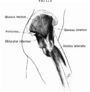
Abductors: The next structures encountered are the abductors (Fig 12e and 12 f). The most important of these is the gluteus medius,
FIG 12 e
which originates from the wing of the ilium just below the crest. The
origin for the gluteus medius extends across the whole breadth of the
wing of the ilium, and the broad fan-shaped muscle narrows to a
distal insertion on the lateral and anterior surfaces on the greater
trochanter. The posterior margin of the gluteus medius is well defined
by a thick tendon, which inserts into the tip of the trochanter just
anterior to the pyriformis tendon insertion.
The gluteus medius is innervated by branches from the superior
gluteal nerve. The next strongest abductor is the gluteus minimus,
which originates from the wing of the ilium just beneath the gluteus
medius. It, too, extends the full width of the wing of the ilium, in this
case just anterior to the greater sciatic notch to the level of the bridge
between the anterior-superior and anterior-inferior iliac spines. From
this broad origin, it narrows sharply to insert onto the
anterior-superior greater trochanter, deep and anterior to the insertion of the
gluteus medius tendon.
External rotators: The flat muscle belly of the pyriformis lies almost parallel to the posterior margin of the gluteus medius. It arises from
the lateral margin of the anterior surface of the sacrum and the
margin of the greater sciatic foramen, passing out of the pelvis
through the greater sciatic foramen to insert into the tip of the greater
tendon of the obturator internus and gemelli. The sciatic nerve passes
deep to the pyriformis. The pyriformis, in addition to being an
abductor, it is also an external rotator. The obturator internus and
gemelli form a common insertion just inside the tip of the trochanter
and deep to the pyriformis tendon. The obturator internus originates
from the inside of the obturator foramen, passing out of the pelvis
through the lesser sciatic foramen and then passing horizontally
across the posterior capsule of the hip, where it receives the
attachments of the gemelli and is inserted into the aforementioned
spot on the trochanter. Its innervation comes from a special nerve
from the sacral plexus within the pelvis (Fig 12 g).
The obturator externus covers the outer surface of the anterior
wall of the pelvis, arising from the margin of the medial side of the
obturator foramen. The fibers end in a tendon that runs across the
back of the neck of the femur and inserts into the trochanteric fossa.
It is innervated from a branch of the obturator nerve. The last of the
important short external rotators is the quadratus femoris, which
arises from the upper part of the external border of the tuberosity of
the ilium and inserts into the upper part of the linea quadrata
extending downward from the intertrochanteric crest. Superior to the
quadratus femoris is the gemellus inferior, and inferior to it is the
FIG 12 g
.
FIG 13 FIG 14
plexus. The quadratus femoris marks the inferior margin of the
muscle release necessary for exposure of the hip through the posterior
approach. The sciatic nerve lies deep to the pyriformis muscle but
superficial to the rest of the external rotators.
Flexors : The psoas tendon inserts into the lesser trochanter of the femur. The muscle fibers of the iliacus extend distal to the lesser
trochanter to insert onto the body of the femur in front of and below
the lesser trochanter. There is usually an indentation in the anterior
lip of the acetabulum where the psoas crosses it. The psoas serves to
reinforce the Y ligament of Bigelow as the hip is extended. The other
flexors located in the anterior aspect of the thigh are sartorius,
pectineus and rectus femoris ,the adductor muscles (longus, brevis &
magnus) and gracilis are located in the medial aspect of thigh.
Vessels about the Hip
The common iliac artery and vein lie on the anterior surface of
the wing of the ilium and cross the superior pubic ramus and pass
medial to the femoral head. The medial femoral circumflex artery
arises from the medial aspect of the profundus and passes between
the pectineus and the psoas major. The acetabular branch from the
ligament and supplies blood to the fat in the bottom of the acetabular
fossa. (Fig 13 and 14).
The lateral circumflex artery arises from the lateral side of the
profunda and passes behind the rectus femoris, dividing into anterior,
transverse, and descending branches. The terminal divisions of the
transverse branch wind around the femur just below the greater
trochanter and may be encountered when splitting the vastus lateralis
fibers in carrying out the direct lateral approach. The superior gluteal
artery passes out of the greater sciatic notch above the pyriformis in
the company of the superior gluteal nerve and passes between the
medius and minimus. The inferior gluteal artery comes out below the
BIOMECHANICS
The forces exerted on the hip have their biological expression in
the form of the femur and acetabulum, particularly in the location and
orientation of the trabecular pattern. When the weight of the body is
being borne on both legs, the center of gravity is centered between the
two hips and its force is exerted equally on both hips (Fig 15).
Under these loading conditions, the weight of the body minus
the weight of both legs is supported equally on the femoral heads, and
the resultant vectors are vertical. When the hips are viewed in the
sagittal plane and if the center of gravity is directly over the centers of
the femoral heads, no muscular forces are required to maintain the
equilibrium position, although minimal muscle forces will be
necessary to maintain balance. If the upper body is leaned slightly
posteriorly so that the center of gravity comes to lie posterior to the
centers of the femoral heads, the anterior hip capsule will become
tight, so that stability will be produced by the Y ligament of Bigelow.
Therefore, in symmetrical standing on both lower extremities, the
compressive forces acting on each femoral head represent
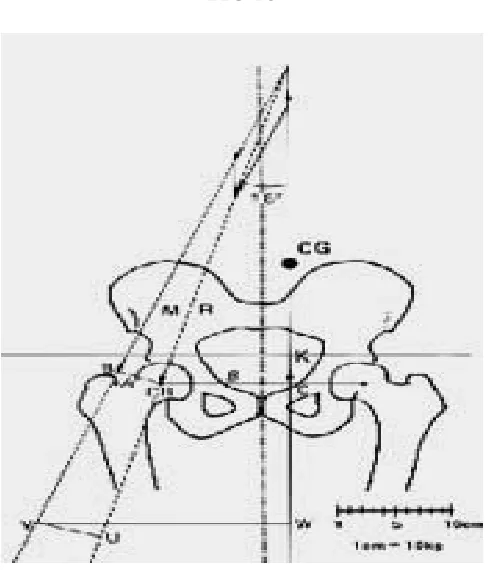
approximately one-third of body weight. In a single leg stance, the
supporting leg since the nonsupporting leg is now calculated as part of
FIG 16
bearing hip. Since the pillar of support is eccentric to the line of action
of the center of gravity, body weight will exert a turning motion
around the center of the femoral head. This turning motion must be
offset by the combined abductor forces inserted into the lateral femur.
In the erect position, this muscle group includes the upper fibers of
the gluteus maximus, the tensor fascia lata, the gluteus medius and
minimus, and the pyriformis and obturator internus. The combined
resultant vector of the abductor group can be represented by the line
of action M (Fig 16). Since the effective lever arm of this resultant force (BO) is considerably shorter than the effective lever arm of body
weight acting through the center of gravity (OC), the combined force of
the abductors must be a multiple of body weight. The vectors of force
K and force M produces a resultant compressive load on the femoral
head that is oriented approximately 16° obliquely, laterally, and
distally.
The orientation of this resultant vector is exactly parallel to the
orientation of the trabecular pattern in the femoral head and neck
(Fig 17). The effect of this combined loading of body weight and the abductor muscle response required for equilibrium results in the
loading of the femoral head to approximately 4 times body weight
during the single leg stance phase of gait. This means that in normal
from one-third of body weight in the double support phase of gait to 4
times body weight during the single leg support phase. The factors
influencing both the magnitude and the direction of the compressive
forces acting on the femoral head are 1) the position of the center of
gravity; 2) the abductor lever arm, which is a function of the
neck-shaft angle; and 3) the magnitude of body weight. Shortening of the
abductor lever arm through coxa valga or excessive femoral ante
version will result in increased abductor demand and therefore
increased joint loading.
If the lever arm is so shortened that the muscles are
overpowered, then either a gluteus minus lurch (the center of gravity
is brought laterally over the supporting hip) or a pelvic tilt
(Trendelenburg gait) will occur. Since the loading of the hip in the
single leg stance phase of gait is a multiple of body weight, increases
in body weight will have a particularly deleterious effect on the total
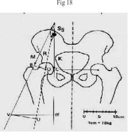
compressive forces applied to the joint. The effective loading of the
joint can be significantly reduced by bringing the center of gravity
closer to the center of the femoral head (Fig 18). Sideways limping however, requires acceleration of the body mass laterally, its
deceleration during the stance phase of gait, and then its acceleration
back to the midline or even to the other side as the single leg stance
energy consumption and is a much less efficient means of ambulation
Fig 18
in which the hip is subjected to these considerable forces. Another
effect of sideways limping is that the resultant vector becomes more
vertical because the center of gravity is acting in a more vertical
direction, and therefore the bending moment the femoral neck is
increased.
Another mechanism for reducing the resultant load on the
femoral head is the use of a walking stick in the opposite hand. Since
some of its force is transferred to the walking stick through the hand,
the effective load of body weight is thus reduced in two ways: 1) the
effective load of body weight is reduced; 2) since the turning moment
around the femoral head is reduced, the abductor demand is also
reduced (Fig 19).
Pauwels has calculated both the total compressive load on the
femoral head and the angle of inclination of the vertical compressive
loads for different forces applied to the walking stick. It can be that
only 9 kg of force applied to a cane in the opposite hand reduces the
load on the femoral head by nearly 40%. The same effect could also be
achieved by a 40% reduction in body weight. Also the angle of
inclination with this degree of unloading is not significantly different
from normal, so that using a stick to unload the femoral head
limping. Therefore, in the rehabilitation of patients after hip
surgeries the use of a stick to prevent sideways limping is always
preferable. The form of the femur and the orientation of the
trabecular pattern in the proximal femoral metaphysis and epiphysis
would support the conclusion that the principal loading of the femoral
head is in the coronal plane. When an individual rises from the
seated position or climbs stairs, the forces of body weight are applied
to the anterior surface of the femoral head. The femur itself is
prevented from rotating in response to this applied load by the
stabilization of the posterior femoral condyles against the tibial
plateaus. In addition the psoas tendon inserting into the lesser
trochanter prevents this applied load from rotating the femur
internally. This anteriorly applied force therefore produces a twisting
strain on the proximal femur. This aspect of loading of the proximal
femur takes on particular importance for femoral stem design since
anteriorly applied loads will produce a twisting strain on the stem
within the medullary canal. Vertical loading of the femoral component
will produce compressive load on the medial side of the femoral stem
and tension loads on the lateral side of the stem, whereas anterior
MECHANISM OF INJURY
Peritrochanteric fractures in young adults are the results of
high energy trauma like road traffic accidents or fall from height and
account for only 10%. In contrast 90% of fractures occurring in
elderly are due to a simple fall. The tendency to fall increases with age
and is exacerbated by several factors like poor vision, decreased blood
pressure, poor reflexes, decreased muscle power, vascular disease and
co-existing musculo skeletal pathology .
Cummins and Nevitt identified four factors they determined whether
a particular fall results in a fracture of the hip.
1. The fall must be oriented so that the person lands on or
near the hip.
2. Inadequate protective reflexes that do not reduce the
energy of fall below a certain critical threshold.
3. Deficient local shock absorbers (muscle and fat around the
hip)
FIG 20
[image:50.612.159.470.146.372.2]SIGNS AND SYMPTOMS
Fractures may be undisplaced or impacted and, such patients
may present with minimal pain at the hip or may present with thigh
pain. They may be ambulant, were as patients with displaced
fractures are clearly symptomatic and usually cannot stand, much less
ambulant. Patients with undisplaced fracture may present with
virtual absence of clinical deformity, where as those with displaced
fractures exhibit the classic presentation of shortened and externally
rotated extremity. There may be tenderness to palpation in the area
of the greater trochanter. Ecchymosis may be present and should be
RADIOGRAPHIC AND OTHER IMAGING
STUDIES
Standard radiographic examination includes AP of the pelvis
and an AP and cross table Lateral view of the proximal femur. The
lateral radiograph can help to assess the posterior comminution of the
proximal femur. An internal rotation view of the injured hip may be
helpful to identify non displaced fractures. Internally rotating the
involved femur 10 to 15◦ offsets the ante version of the femoral neck
and provides a true AP of the proximal femur. A second AP of the
contra lateral side can be used for pre operative planning.
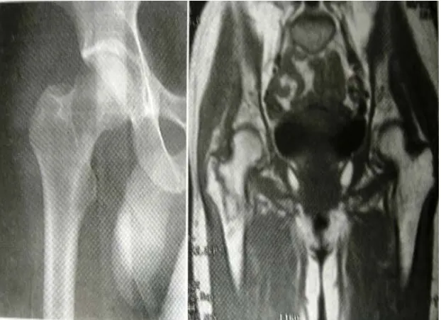
When hip fracture is suspected but not apparent on standard
radiographs a technetium bone scan or a MRI scan should be obtained
(Fig 20 & 21). Two or three days may be required before a bone scan becomes positive, but MRI can reveal occult fractures within 24 hours
of injury.3d CT scans can be useful to determine the extent and
severity of comminution so that pre-operative planning and implant
CLASSIFICATION
The commonly used classification is the Boyd & Griffin
classification.
Boyd & Griffin classification (1949) included all fractures from the extra capsular part of neck to a point 5cm distal to the lesser
trochanter (Fig 22).
Type I: Fractures that extend along the intertrochanteric line from the greater to the lesser trochanter .reduction is usually simple
and maintained with little difficulty. Results are generally
satisfactory.
Type II: Comminuted fractures, the main fracture being along the intertrochanteric line but with multiple fractures in the cortex.
Reduction of these fractures are more difficult because the
comminution can vary from slight to extreme. A particularly
deceptive form of the fracture is one where in there is an antero –
posterior linear intertrochanteric fracture occurs a s in type I but
with an additional fracture in the coronal plane.
Type III: Fractures that are basically sub trochanteric with at least one fracture passing across the proximal end of the shaft just
are associated. These fractures are usually more difficult to reduce
[image:55.612.145.486.151.648.2]and
result in more complications, both during operation and during
convalescence.
Type IV: Fractures of the trochanteric region and the proximal shaft, with fracture in at least two planes, one of which is the sagittal
plane and may be difficult to see in the routine AP radiograph. If
open reduction & internal fixation are used two plane fixation is
required because of the spiral, oblique or butterfly fracture of the
shaft.
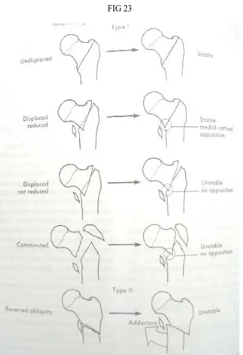
Evans classification (1949)
Evans devised a widely used classification system based on the
division of fractures into stable and unstable groups. He divided the
unstable fractures further into those in which stability could be
restored by anatomical or near anatomical reduction and those in
which anatomical reduction would not create stability (Fig 23).
Type I: Fracture line extends upwards and outwards from the lesser trochanter.
Type II: Reverse obliquity fracture – the major fracture line extends outward and downward from the lesser trochanter. These
fractures have a tendency towards medial displacement of the femoral
Fig 24
[image:57.612.223.405.418.646.2]OTA classification
In orthopedic trauma association alpha – numeric fracture
classification intertrochanteric fractures are typed 31A (Fig 24).
Group I: Simple two part fractures.
Group II: Comminuted fractures with a postero medial fragment, the lateral cortex of the Greater trochanter however remains intact.
Group III: Fractures in which the fracture line extends across both the medial & lateral cortices. This group includes the reverse obliquity
pattern.
Unusual Fracture Patterns
Basicervical neck fractures are located just proximal to or along
the inter trochanteric line. Though Basicervical fractures are
considered extra capsular this may not always be the case.
Basicervical fractures are thus at greater risk of osteonecrosis than
the more distal intertrochanteric fractures. Further more Basicervical
fractures lack the cancellous inter digitations seen with fractures
through the intertrochanteric region and are more likely to sustain
The intertrochanteric region of the hip consisting of the area
between the greater and lesser trochanters representing a zone of
transition from femoral neck to the femoral shaft. The greater and
lesser trochanters are the sites of insertion of the major muscles of the
gluteal region, the short external rotators, the abductors and the
iliopsoas. The calcar femorale extending from the posteromedial
aspect of the femoral shaft to the posterior part of the femoral neck
forms an internal trabecular strut within the inferior portion of the
femoral neck and the intertrochanteric region and act as a strong
HISTORICAL REVIEW
1564 - Ambrose Pare′ initially described fractures of the proximal femur.
1882 - Sir Jacob Astley Cooper was the first to distinguish between intra and extra capsular fractures. In those times
therapeutic options were few and patients were treated with bed
rest.
19th century – Concept of traction was introduced with the goal of
minimizing limb. Shortening and deformity from the middle of this
century. But prolonged bed rest in traction until fracture healing
occurred ( usually 10 to 12 weeks ) followed by a lengthy programme
of ambulation training was associated with high complication rates
especially with elderly like decubitus ulcers, UTI, joint contractures,
pneumonia and thrombo embolic complications resulting in high
mortality rate. In addition fracture healing was generally
accompanied by varus deformity and shortening because of inability of
traction to effectively counteract the deforming muscular forces.
1960’s – Operative management consisting of fracture reduction and stabilization which permits early patient mobilization and minimizes
many of the complications of prolonged bed rest became the treatment
Non-operative management: Nevertheless there remain situation where surgery cannot be performed like
1. An elderly person whose medical condition carries an
excessively high risk of mortality from anesthesia and surgery
2. Non ambulatory patient who has minimal discomfort following fracture
Non-operative protocols took one of two different approaches:
a. Early mobilization within the limits of patients discomfort and acceptance of deformity. Patient was allowed out of
bed and in a chair within a few days of injury but
ambulation was delayed.
b. Attempt to establish and maintain a reasonable reduction via skeletal traction until fracture union occurred.
When non operative management is required in elderly the first
approach is better because it avoids complications of prolonged bed
rest, which is important than attempting often unsuccessful task of
Fig 26
Operative management - The first successful implants were
Fixed - angle nail plate devices :
Jewett nail, Holt nail consisting of a tri-flanged nail fixed to a plate at an angle of 130 to 150◦(Fig 26).
While these devices provided stabilization of femoral head and
neck fragment to the femoral shaft, they did not provide controlled
fracture impaction. If significant impaction of the fracture site
occurred the implant would either penetrate into the hip joint or
cutout through the superior portion of the femoral portion and neck.
On the other hand if no impaction occurred lack of bony contact would
result in either plate breakage or separation of the plate and screws
from the femoral shaft. These complications occurred more frequently
in cases of unstable fractures. So experiences with these indicated the
need for a device that allows controlled fracture impaction. This gave
rise to,
Sliding – nail plate devices:
Massie nail ,Ken-Pugh nail (Fig 27) consisting of a nail that provided proximal fragment fixation and a side plate that allowed the
which promoted fracture union and decrease the stresses on implant,
thereby lowering the risk of implant failure.
FIG 28
Kyle et al reported a lower incidence of nail breakage and fewer
cases of nail penetration with a Massie sliding nail than with a fixed –
angle Jewett nail for the treatment of unstable trochanteric fractures.
Sliding hip screw devices:
In these devices the nail portion was replaced by a blunt ended
screw with a large outside thread diameter. Theoretically these
alterations would result in improved proximal fragment fixation and
decrease the risk of screw cutout by eliminating the sharp edges found
on tri-flanged nails. Numerous series have reported excellent results
and became the most widely used devices.
Bi-directional sliding:
One early modification to the sliding hip screw maximized
fracture impaction by allowing the proximal lag screw to telescope
within the barrel and the plate to slide axially along the femoral shaft
creating the bi-directional sliding by replacing the rounded screw
holes with slotted screw holes, e.g. Egger’s plate (Fig 28 a,b, c, d, e, f&g).
More recently a 2 component plate device was introduced, e.g.
internal sliding component. Both devices have been successfully used
[image:66.612.223.417.182.509.2]for the treatment of stable and unstable trochanteric fractures.
Fig 29
The Alta expandable dome plunger (How medica):
It is a modified sliding hip screw designed to improve fixation of
the proximal fragment with facilitating cement intrusion into the
femoral head. Cement is kept away from the plate barrel so that the
device’s sliding potential is maintained. Although this device is
demonstrably superior to the standard sliding hip screw system in
laboratory testing, improved efficacy has not been shown in clinical
trials.
Intertrochanteric osteotomies:
Emphasizing that restoration of medial continuity is essential
for successful internal fixation of three and four part intertrochanteric
fractures, in the absence of stable medial buttress the following
methods were subsequently developed to achieve stable medial
cortical apposition.
1. Dimon-Hughston medial displacement osteotomy (Fig 29 a)
2. Sarmiento valgus osteotomy (Fig 29 b)
3. Wayne County lateral displacement osteotomy (Fig 29 c)
These methods provide stable but non – anatomic alignment.
FIG 30
(a)
interest in anatomic alignment. Anatomic alignment differs
from anatomic fracture reduction in that its goal is simply to align the
head and neck fragment with shaft rather than reduce and stabilize
all fracture fragments.
Because a sliding hip screw allows controlled fracture collapse
anatomically aligned unstable fractures that are stabilized with a
properly inserted sliding hip screw usually move spontaneously to a
stable medially displaced position as reported by Hopkins et al.
Knowledge of these techniques is still occasionally useful in some
extremely comminuted fractures where anatomic reduction is not
possible.
Intramedullary devices:
Further progression lead to the development of intra medullary
devices (Fig 30 a), which are subjected to lesser bending movements than plate and screw devices because they are positioned closer to the
mechanical axis of femur. The longest experience has been the use of
flexible intra medullary nails e.g. Ender’s nail (Fig 30 b), inserted under image intensifier in retrograde fashion through portals in the
While the advantages of this procedure were supposed include –
• Closed fracture reduction and fixation where fracture hematoma is not disturbed
• Decreased blood loss
• Reduced anesthetic and operating time
• Reduced mortality
But in practice their use has been associated with a significant
incidence of complications like rotational deformity, supra condylar femur fracture, proximal migration of nail through femoral head and
back out of the nails with resultant knee pain and stiffness.
Cephalo – medullary nails:
Recently renewed interest is being given to cephalo – medullary
fixation devices because of several potential advantages (Fig 31),
1. An intra medullary fixation device because of its location theoretically provides more efficient load transfer than a sliding hip screw.
2. The shorter lever arm of the IM device can be expected to decrease tensile strain thereby decreasing the risk of
implant failure.
3. Because it incorporates sliding mechanism with the hip
FIG 32
(a) (b) (c)
4. Insertion of an IM device theoretically requires shorter operative time and less soft tissue dissection than a sliding
hip screw – plate devices thereby potentially resulting in
decreased overall morbidity.
Examples :- IMHS ( intra medullary hip screw – Fig 32 a) - Gamma nail (Fig 32 b)
- Russel – Taylor reconstruction nail ( Fig 32 c ) - ATN ( Ante grade trochanteric nail)
- TFN ( Trochanter fixation nail - Fig 32 d) and - PFN ( Proximal femoral nail – Fig 32 e)
These devices are Centro - medullary nails which couple, an
intra medullary hip screw (for proximal fixation into the femoral head
and neck Fragment ) + a distally locked intra medullary nail
The gamma nail, IMHS, ATN and TFN began as shorter nails
than reconstruction nails with a tip ending within the diaphysis of the
femur. However they have the disadvantage of increased risk of
femoral shaft fractures at the nail tip and the insertion sites of the
distal locking screws. Severe deformities of the femoral canal or
excessive anterior bowing may preclude the use of an intra medullary
To prevent the occurrence of femoral shaft fractures
modification of these nails by tapering the distal diameters lead to the
introduction of proximal femoral nail.
Proximal femoral nail:
PFN is considered to be the second generation nail, was
introduced during 1997 by Synthes company in Czech Republic for treatment of unstable peritrochanteric fractures. PFN is 240 mm in length is made of 316 LVM stainless steel or titanium. 2 proximal screws can be inserted into the femoral neck through the proximal part of the nail. The load bearing neck screw is 11 mm and the tip of it should be placed subchondrally into the distal half of femoral
head. The other screw is a 6 mm derotation – proximal pin and should be placed through the upper part of the nail into the proximal
half of the femoral neck to prevent rotation of the head and neck
fragment. 2 distal interlocking bolts of 4.9 mm size is inserted through the distal part of the nail connecting the lateral and the
medial cortex of the shaft. It has both dynamic and static locking . The proximal end of PFN is 17.5 mm in diameter.
A randomized study conducted by Pajarinen .J et al 2005
comparing peritrochanteric fractures treated with a DHS and PFN
reported that patients treated with PFN had regained their pre –
injury working ability significantly faster compared to patients
neck (loss of hip offset) and femoral shaft (loss of leg length). In the
patients treated with DHS. The difference in shortening of femoral
neck was 5 mm and was statistically significant.
Banan.H et al in 2002 from Essex, UK after stabilizing 60 consecutive femoral neck fractures with PFN suggested the use of
PFN for unstable trochanteric fractures is very encouraging but a
large randomized trial with DHS would be helpful to clarify the
relative risks and benefits.
Al – Yassari .G et al in 2002 from Middlesex, UK treated 76 patients with unstable trochanteric fractures with PFN and reported
it as a relatively easy procedure and a biomechanically stable
construct allowing early weight bearing, but femoral neck screw
positioning as critical.
Pavelka .T et al in 2003 from Czechoslovakia did a 4 year study and reported PFN as an excellent implant for the treatment of
unstable fractures of proximal femur and the successful outcome
includes a good understanding of fracture biomechanics, correct
indication and exactly performed osteosynthesis.
K.J.Simmermacher et al in 1999 from Netherlands after 1 year study of 191 cases in four European clinics reported that PFN
Gamma nail used for the treatment of unstable peritrochanteric
fractures.
Schipper I.B. et al in 2002 from Netherlands after studying biomechanical behavior of PFN suggested slotted hole for the
derotational hip pin to decrease the excessive weight loading of the
hip pin thereby preventing its cutout, which is the most serious
complication encountered.
Klinger H.M. et al in 2005 from Germany after 3 years period of study comparing DHS versus PFN fixation in 173 patients with
unstable trochanteric fractures reported considerably shorter
operating time, shorter in-patient stay, immediate full weight bearing
and decreased incidence of complications with PFN .
Although several authors reported in favor of PFN for unstable
trochanteric fractures regarding easy surgical procedure, reduced
blood loss, reduced operating time, better biomechanical stability and
early mobilization the role of intra medullary devices like PFN in
favor of DHS for unstable trochanteric fractures require precise
surgical technique and expertise, adequate learning curve, accurate
placement of lag screw in femoral head and good selection of cases.
However a longer duration of study comparing the performance of
POST OPERATIVE CARE
The mobilization of hip fracture patients out of bed and
ambulation training be initiated on post operative day 1. Further
more, any patient who has been surgically treated for an
intertrochanteric fracture should be allowed to bear weight as
tolerated. Restricted weight bearing after hip fracture has little
biomechanical justification, since activities such as moving around in
bed and use of a bed pan generate forces across the hip approaching
those resulting from unsupported ambulation. Even foot and ankle
range of motion exercises performed in bed produce substantial loads
on the femoral head secondary to muscle contraction.
Since the goal in all trochanteric fractures is to provide early
mobilization and the best chance for functional recovery, the role of
immediate restricted and unrestricted weight bearing depends upon
the type of fracture (stable or unstable) and the ability of the patient
to support them with their upper extremity. Although literature
studied show immediate unrestricted weight bearing with support
does not increase complication rate (Ecker et al) there is still 2.5 to 5
% of requirement of revision surgery, more prevalent in unstable
trochanteric fractures as high as 20 % and they attribute it to poor
If the fracture pattern is stable, the internal fixation rigid and
the device is biomechanically superior unrestricted immediate weight
bearing can be allowed. On the other hand if the fracture pattern is
COMPLICATIONS
Loss of fixation:
Fixation failure with either a sliding hip screw or an
Intramedullary device is most commonly characterised by varus
collapse of the proximal fragment with cutout of the lag screw from
the femoral head. The incidence of fixation failure is reported to be as
high as 20% in unstable fracture patterns. Lag screw cut out from the
femoral head generally occurs within 3 months of surgery and is
usually due to
a. Eccentric placement of the lag screw within the femoral head
b. Improper reaming that creates a second channel
c. Inability to obtain a stable reduction
d. Excessive fracture collapse such that the sliding capacity of the device is exceeded
e. Inadequate screw – barrel engagement which prevents sliding
f. Severe osteopenia which precludes secure fixation .
a. Acceptance of the deformity
b. Revision ORIF, which may require methylmethacrylate
c. Conversion to prosthetic replacement
Acceptance of the deformity should be considered in marginal
ambulators who are a poor surgical risk. Revision ORIF is indicated in
younger patients. While conversion to prosthetic replacement
(unipolar, bipolar or total hip replacement) is performed in the
elderly patient with osteopenic bone.
Non union
Non union following surgical treatment of intertrochanteric
fractures occurs in < 2 % of patients. Its rare occurrence is largely due
to the fact that the fracture occurs through well – vascularized
cancellous bone. The incidence of non union is highest in unstable
fracture patterns. Mariani and Rand et al in 1987 reported on 20 nonunion, 19 of which (95%) occurred in fracture with loss of
posteromedial support. Most intertrochanteric nonunion following
unsuccessful operative stabilization with subsequent varus collapse
and screw cutout through the femoral head. Another possible etiology
for intertrochanteric non union is an osseous gap secondary to
inadequate fracture impaction. This can occur as a result of jamming
of the lag crew within the plate barrel or mismatch of the lag screw
slide. Both problems can be avoided with proper attention to the
details of device insertion.
Intert rochanteric non union should be suspected in patients
with persistent hip pain that have radiographs revealing a persistent
radioluscency at the fracture site 4 to 7 months after fracture
fixation. Progressive loss of alignment strongly suggests non union,
although union may occur after an initial change in alignment
particularly if fragments contact improves. Abundant callus formation
may be present, making the diagnosis of non union difficult to
confirm. Tomography evaluation may help to confirm the diagnosis.
Otherwise the diagnosis may not be possible until the time of surgical
exploration. As with any non union, the possibility if an occult
infection must be considered, however in most elderly individuals
conversion to a calcar replacement prosthesis is preferred.
Malrotation Deformity
The usual cause of malrotation deformity after intertrochanteric
fracture fixation is internal rotation of the distal fragment at surgery.
In unstable fracture patterns, the proximal and distal fragments may
move independently. In such cases the distal fragment should be
placed in neutral to slight external rotation during fixation of the
plate to the shaft. When malrotation is severe and interferes with
ambulation, revision surgery with rotational osteotomy of the femoral
Other Complications
Osteonecrosis of the femoral head is rare following
intertrochanteric fracture. No association has been established
between location of the implant within the femoral head and
development of osteonecrosis, although one should avoid the postero
superior aspect of the femoral head because of the proximity to the
lateral epiphyseal arterial system.
Various case reports have documented unusual complications
relating to lag screw back out and migration into the pelvis. Most
cases of lag screw migration into the pelvis occur in unstable fractures
and are associated with improper reaming and violation of the hip
joint or the presence of inadequate screw – barrel engagement. “Z“ effect noted in PFN with reversal of derotation – proximal pin and penetration of the lag screw into the hip joint can be avoided by
creating a slotted hole for proximal pin and accurate placing of the lag
screw (within 5mm of subchondral bone), so that weight bearing
occurs through the lag screw into the Intramedullary nail and also
allows the proximal pin to yield during weight transmission .
Laceration of the superficial femoral artery by a displaced lesser
trochanter fragment has been reported as well as binding of the guide
pin within the reamer, resulting in guide pin advancement and
MATERIALS AND METHODS
At our institution we selected 21 cases of peritrochanteric
fractures for this prospective study. All 21 cases were treated with
proximal femoral nail (indigenous) of which 20 patients came for
regular follow up and they were included in the study. The age group
varied from a minimum of 32 years to a maximum of 72 years and
average age was 52.7 years. The duration of the study was from June
2004 to June 2006. The mean follow up was 10.75 months. Of the 20
patients 14 were males and 6 were females. Right side was involved in
7 patients and in 13 patients the left side was involved. 13 patients
were sedentary workers and 7 patients were manual laborers.
All the fractures were classified according to the Boyd and
Griffin classification for peritrochanteric fractures.
11 patients were classified as type II
4 patients were classified as type III
5 patients were classified as type IV
AGE
SEX
Proximal Femoral Nail Sex
No. %
Male 14 70.0
Female 6 30.0
Proximal Femoral Nail Age Group
(Years)
No. %
31 – 40 3 15.0
41 – 50 6 30.0
51 – 60 6 30.0
61 – 70 4 20.0
> 70 1 5.0
Proximal Femoral Nail 15 30 30 20 5 0 20 40 60 80 100 120 1 Age Pe rc e n ta g e
31 – 40 41 – 50 51 – 60 61 – 70 > 70
SEX
70% 30%
MODE OF INJURY
Accidental fall was the most common followed by RTA
Proximal Femoral Nail Mode of Injury
No. %
Accidental Fall 13 65.0
RTA 7 35.0
INTERVAL BETWEEN INJURY & SURGERY
Proximal Femoral Nail Intervals
(Days)
No. %
<2 - -
2 1 5.0
3 2 10.0
4 3 15.0
5 4 20.0
6 5 25.0
7 2 10.0
8 2 10.0
9 1 5.0
>9 - -
Total 20 100
MODE OF INJURY
65% 35%
Accidental Fall RTA
Interval between injury & surgery
0
5
10
15
20
25
10
10
5
0
0
5
10
15
20
25
30
<2
2
3
4
5
6
7
8
9
>9
CLASSIFICATION
Proximal Femoral Nail Classification
(Boyd & Griffin) No. %
I - - II 11 55.0 III 4 20.0 IV 5 25.0 Total 20 100
Associated Injuries
Colle’s fracture - 1 case
Fracture shaft of humerus - 1 case
The average interval from injury to the time of surgery was 5
days. All the patients were managed initially with skin traction
before taking up for surgery. Patient with Colle’s fracture and
fracture shaft of humerus were treated with CMR with POP
immobilization for Colle’s fracture on the day of admission and ORIF
of fracture shaft of humerus after internal fixation of the trochanteric
fracture.
Preoperative Planning
Preoperative templating with AP X-ray of the pelvis was done in
the uninjured femur in internal rotation and the nail diameter and