This is a repository copy of
A Deep Learning-Based Approach to Power Minimization in
Multi-Carrier NOMA with SWIPT
.
White Rose Research Online URL for this paper:
http://eprints.whiterose.ac.uk/141652/
Version: Accepted Version
Article:
Luo, Jingci, Tang, Jie, So, Daniel et al. (3 more authors) (Accepted: 2019) A Deep
Learning-Based Approach to Power Minimization in Multi-Carrier NOMA with SWIPT. IEEE
Access. ISSN 2169-3536 (In Press)
[email protected] https://eprints.whiterose.ac.uk/ Reuse
Items deposited in White Rose Research Online are protected by copyright, with all rights reserved unless indicated otherwise. They may be downloaded and/or printed for private study, or other acts as permitted by national copyright laws. The publisher or other rights holders may allow further reproduction and re-use of the full text version. This is indicated by the licence information on the White Rose Research Online record for the item.
Takedown
If you consider content in White Rose Research Online to be in breach of UK law, please notify us by
A Deep Learning-Based Approach to Power
Minimization in Multi-Carrier NOMA with SWIPT
Jingci Luo, Jie Tang,
Senior Member
,
IEEE
, Daniel So,
Senior Member
,
IEEE
,
Gaojie Chen
Senior Member
,
IEEE
, Kanapathippillai Cumanan,
Senior Member
,
IEEE
,
and Jonathon Chambers,
Fellow
,
IEEE
Abstract—Simultaneous wireless information and power trans-fer (SWIPT) and multi-carrier non-orthogonal multiple access (MC-NOMA) are promising technologies for future fifth gener-ation (5G) and beyond wireless networks due to their potential capabilities in energy-efficient and spectrum-efficient system designs, respectively. In this paper, the joint downlink resource allocation problem for a SWIPT-enabled MC-NOMA system with time switching (TS)-based receivers is investigated, where pattern division multiple access (PDMA) technique is employed. We focus on minimizing the total transmit power of the system whilst satisfying the quality-of-service (QoS) requirements of each user in terms of data rate and harvested power. The corresponding optimization problem is a non-convex and a mixed integer programming problem which is difficult to solve. Different from the conventional iterative searching-based algorithms, we propose an efficient deep learning-based approach to determine an approximated optimal solution. Specifically, we employ a typical class of deep learning model, namely deep belief network (DBN), where the detailed procedure of the developed approach consists of three parts, i.e., data preparation, training and running. Simulation results demonstrate that the proposed DBN-based approach can achieve a similar performance of power consumption to the exhaustive search method. Furthermore, the results also confirm that MC-NOMA with PDMA outperforms MC-NOMA with sparse code multiple access (SCMA), single-carrier non-orthogonal multiple access (SC-NOMA) and orthog-onal frequency division multiple access (OFDMA) in terms of power consumption in SWIPT-enabled systems.
Index Terms—Non-orthogonal multiple access (NOMA), si-multaneous wireless information and power transfer (SWIPT), machine learning.
I. INTRODUCTION
With the dramatically rapid development of mobile Internet and the exponential growth of connected devices, the future
This work has been supported in part by the National Natural Science Foundation of China under Grant 61601186, in part by the Natural Science Foundation of Guangdong Province (2017A030313383), and in part by the open research fund of National Mobile Communications Research Laboratory, Southeast University (No. 2019D06).(Corresponding author: Jie Tang.)
J. Luo is with the School of Electronic and Information Engineer-ing, South China University of Technology, Guangzhou, China. (e-mail: [email protected]).
J. Tang is with the School of Electronic and Information Engineering, South China University of Technology, Guangzhou, China, and also with National Mobile Communications Research Laboratory, Southeast University, Nanjing 210096, China (e-mail: [email protected]).
D. K. C. So is with the School of Electrical and Electronic Engi-neering, University of Manchester, Manchester, United Kingdom. (e-mail: [email protected]).
K. Cumanan is with the Department of Electronic Engineering, University of York, United Kingdom. (e-mail: [email protected]).
G. Chen and J. A. Chambers are with the Department of Engineering, University of Leicester, United Kingdom. (email: [email protected]; [email protected]).
wireless networks are expected to provide much higher data rate which enables supporting the proliferation of the Inter-net of things (IoT), massive machine-type communications (mMTC), etc [1]. However, the available radio spectrum is far from sufficient to support the unexpected high demands for data services, and hence it is particularly important to improve spectrum efficiency (SE) in the spectrum-limited systems. The conventional orthogonal multiple access (OMA) schemes, including orthogonal frequency-division multiple ac-cess (OFDMA) which is widely used in the fourth generation (4G) cellular systems, are increasingly arduous to fulfill the aforementioned unprecedented requirements due to the limited improvement of SE in orthogonal channel access [2]. The non-orthogonal multiple access (NOMA) technique, which allows multiple users to share the same time-frequency resource element (RE), has been recognized as the potential multiple access technique to achieve higher SE in future fifth gener-ation (5G) and beyond wireless networks [3]. Furthermore, heterogeneous requirements such as low latency, ultra-reliability and massive connectivity are more likely to be realized in NOMA systems.
Since the system-level performance of NOMA has been proved to be superior to OMA under various wireless en-vironments in [4]–[6], NOMA has attracted a significant attention in both academia and industry. Several forms of NOMA techniques have been proposed for 5G and beyond wireless networks. Depending on whether the total available spectrum resource is or is not divided into several subcarri-ers, NOMA can be classified into two main types, namely single-carrier NOMA (SC-NOMA) and multi-carrier NOMA (MC-NOMA), respectively. The power-domain NOMA (PD-NOMA) is a well-known and promising SC-NOMA technique [7], in which multiple users are multiplexed with different transmit power levels in the same frequency RE and successive interference cancelation (SIC) is employed at the receiver ends to remove the corresponding co-channel interference so that better performance in terms of SE, energy efficiency (EE) or proportional fairness can be achieved [8], [9]. On the other hand, sparse code multiple access (SCMA) [10] and pattern division multiple access (PDMA) [11] are two most well-known techniques of NOMA. In fact, these two MC-NOMA techniques can be considered as the superposition of multiple PD-NOMAs in different frequency REs [12].
caused by wireless communication systems and the global en-ergy shortage is intensifying. Thus, it is crucial to improve EE in future wireless networks for their sustainability. Motivated by the progress in the research on wireless power transfer (WPT) [13] and the fact that the radio frequency (RF) signal is the carrier of both information and energy, an advanced tech-nology namely simultaneous wireless information and power transfer (SWIPT) has been identified to meet the demanding requirements in future wireless networks in [14]. In order to deal with the sensitivity difference between the information re-ceiver and the energy rere-ceiver, two practical rere-ceiver architec-ture designs namely time switching (TS) and power splitting (PS) have been developed in [15] where information decoding (ID) and energy harvesting (EH) could be separated through time domain and power domain, respectively. The purpose of SWIPT is to reduce energy waste and prolong the battery-life of communication terminals by simultaneously harvesting energy and receiving information. Furthermore, SWIPT is viewed as a potential energy-efficient solution for 5G and beyond wireless networks [13] and a great deal of research has been carried out on the application of SWIPT technology in different systems, including OFDMA systems [16], multiple-input single-output (MISO) systems [17], [18], multiple-multiple-input multiple-output (MIMO) systems [19], heterogenous cellular networks [20] and two way cooperative networks [21], etc.
A. Related works
In the literature, many works have explored the combination of SWIPT technology and NOMA network to reduce the power consumption of the terminals. For instance, studies on SWIPT-based SC-NOMA systems have been investigat-ed in [22]–[26]. Specifically, the work in [22] considerinvestigat-ed incorporating the SWIPT in cooperative MISO SC-NOMA systems and developed a strategy of jointly optimizing PS ratio and the beamforming vectors to maximize the data rate of the “strong user” while satisfying the QoS requirements of “weaker user”. In [26], sum secrecy rate (SSR) maximization problem was addressed in a SWIPT-based SC-NOMA system, and the numerical results demonstrated that the performance gains in terms of SSR could be achieved over the conventional OMA as well as the SWIPT-based OMA systems.
Additionally, Zhai et al. have combined the SWIPT with MC-NOMA in [27] by employing SCMA technique where an optimization framework was developed to strike a good balance between the conflicting performance metrics, namely, data rate and harvested energy. Nevertheless, the performance of the combination of the SWIPT and the MC-NOMA with PDMA remains unknown. Since Zeng et al. have confirmed that PDMA outperforms SCMA in terms of both system throughput performance and block error ratio (BLER) perfor-mance [28], it is worth studying on SWIPT-aided MC-NOMA systems with PDMA technique.
B. Contributions
In this paper, we solve a power minimization problem in the downlink of SWIPT-enabled and PDMA-based MC-NOMA
system with TS-based receivers. In particular, we aim to de-velop a joint optimal solution of subscarrier assignment, power allocation as well as the TS ratio. In general, this kind of joint resource allocation problems are non-deterministic polynomial (NP) hard, and thus the corresponding optimal solutions are of great computational complexity with conventional approaches. Recently, deep learning methods have been exploited to solve the fundamental high complex resource allocation problems in wireless communication systems. More specifically, deep learning methods were developed for solving the problem of route estimation in [29], network traffic classification in [30], mobility prediction [31], resource allocation [32], etc. Motivated by the aforementioned works, we exploit deep learning technique to determine an approximated optimal joint resource allocation strategy for the complicated optimization problem in the considered system.
The main contributions in this work are summarized in the following:
• A deep learning-based resource allocation framework is developed to solve the high complex power minimization problem, which consists of three parts:
1) Data preparation: we randomly generate a set of channel gains, i.e., the input of the training sample; and then we apply the well-known genetic algorithm to determine the corresponding optimal solution, i.e., the output of the training sample.
2) Training:we establish a deep belief network (DBN) for each parameter to be optimized, and train the DBNs based on the obtained samples through both unsupervised and supervised trainings.
3) Running: with a given input (channel gains), the well-trained DBNs are exploited to directly approx-imate the optimal solution of the considered power minimization problem.
• Numerical results demonstrate that the developed deep learning-based approach can achieve a similar perfor-mance of power consumption to the exhaustive search method as well as the genetic algorithm.
• It is also proven that the performance of the proposed MC-NOMA with PDMA is superior to that of the existing MC-NOMA with SCMA, SC-NOMA and OFDMA in SWIPT-enabled systems in terms of power saving. The remainder of this paper is organized as follows. In Sec-tion II, we present the system model of the considered SWIPT-enabled MC-NOMA system with PDMA and mathematically formulate the total transmit power minimization problem. The proposed deep learning-based resource allocation framework is defined and developed in Section III. In Section IV, we evaluate the performance of our proposed algorithm through numerical simulations. Finally, the conclusions of this work are provided in Section V.
The following notations are used throughout the paper. We use the lower-case boldface letters for vectors and uppercase boldface letters for matrices. N denotes the natural number
set while R+ denotes the non-negative real number set. E[|x|2]represents the energy of signal xandx′ indicates the
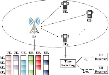
Fig. 1: The system model of a downlink SWIPT-enabled MC-NOMA with TS-based receivers and PDMA technique.
II. SYSTEMMODEL ANDPROBLEMFORMULATION In this section, we first present the system model of the downlink of SWIPT-enabled MC-NOMA with TS-based re-ceivers and PDMA technique. Then the total transmit power minimization problem is mathematically formulated.
A. System Model
As shown in Fig. 1, the considered downlink SWIPT-enabled MC-NOMA system consists of a base station (BS) and K users superposed on N subcarriers through PDMA technique. It is assumed that the transmitter and all the receivers are equipped with one single antenna. Let us denote the set of all users’ indexes by K , {1,2, . . . , K} while the set of all subcarriers’ indexes by N , {1,2, . . . , N}. The total bandwidth B is equally divided intoN subcarriers and thus the bandwidth of each subchannel is denoted as
Bc = B/N. It is assumed that there is no interference between different subchannels due to the orthogonal frequency division. Note that PDMA is based on SIC amenable multiple access (SAMA) technique which can be completed in different domains such as code domain, power domain, space domain or their combinations. In particular, the design of PDMA includes unequal diversity at the transmitter side and equal diversity at the receiver side. For convenience, the mapping of transmitted signal to a group of subcarriers can be described as a N×K characteristic pattern matrixQPDMA∈NN×K.
The element in the nth row and thekth column ofQPDMA
qn,k = 1indicates the signal transmitted to thekth user (UEk) is superposed on the nth subcarrier (REn) while qn,k = 0 indicates the opposite. Let Nn ={k|qn,k = 1}(n∈ N)and
|Nn| = PKk=1qn,k(n ∈ N) respectively denote the set and the number of UEs mapped on REn.
For example, the corresponding characteristic pattern matrix of the mapping schematic diagram in Fig. 1 can be given as
QPDMA(4,6)=
1 1 0 1 1 0 1 0 1 1 1 1 1 1 1 0 1 0 1 0 1 1 0 1
, (1)
where the signal of the UE1 is mapped to all four REs; the
signal of the UE2 is superposed in the RE1 and RE3; etc.
The number of transmission diversity of these six UEs is 4, 2, 3, 3, 3 and 2, respectively. Moreover,N1={1,2,4,5}and |N1|= 4, etc.
We denote the transmit power allocated to the UEk on REn as Pn,k. Hence, the received signal of UEk via REn can be expressed as
yn,k =hn,k
qn,k
p
Pn,kxn,k+
X
j∈K, j6=k
qn,j
p
Pn,jxn,j
+zn,k,
(2)
where hn,k = gn,kd−kβ denotes the channel coefficient from the BS to UEkvia REn;gn,k represents the small-scale fading and follows a Rayleigh distribution with unit variance. The
d−kβdenotes the large-scale fading;dk is the distance between the BS and UEk while β is the related path-loss exponent;
xn,k (xn,j) is the data symbol transmitted from the BS to UEk (URj) via subcarrier REn with unit energy E[|xn,k|2] (E[|xn,j|2]); and zn,k ∼ CN(0, σ2
Since the subcarrier sharing will inevitably cause intra-band interference, SIC technology is employed at the receiver side to mitigate the interference and improve the decoding perfor-mance. Let π(n),(πn(1), πn(2), . . . , πn(|Nn|))denote the
decoding order of the UEs on REn, which can be viewed as a vector function of the CNR of each UE mapped on REn, i.e.,ehn,k (k∈ Nn). In particular, in the downlink of NOMA, the cancellation order at every UE is always to decode the UEs with weaker CNR and subtract the signals of these UEs firstly, and then decode its own data by treating the signals of the remaining UEs on REn as interference [33]. Hence, we have ehn,π(1) < ehn,π(2) < . . . < ehn,π(|Nn|). Based on
SIC technique and with this decoding order, the normalized interference for UEk on REn is hence given by
In,k=ehn,k
X
j∈Nn,
e hn,j>ehn,k
qn,jPn,j. (3)
Accordingly, the signal to interference-plus-noise ratio (S-INR) of UEk on REn can be written as
γn,k=
e
hn,kqn,kPn,k 1 +In,k
. (4)
In practice, the outage may occur if the SINR does not meet the minimum SINR requirement γ, which will lead to the failure of SIC process. In order to avoid this outage, we must have the following condition:
γn,k≥γ, ∀n∈ N, ∀k∈ Nn. (5)
With this condition, the available data rate of UEk on REn can be written as
Rn,k=Bclog2(1 +γn,k). (6)
Furthermore, we consider SWIPT-enabled UE in our pro-posed system model, which consists of an ID circuit and an EH rectification circuit. TS scheme is employed to achieve ID and EH in two orthogonal time slots. For UEk,αk and1−αk correspond to the portion of transmission time allocated to ID and EH, respectively. Hence, the data rate of UEk based on TS scenario can be denoted as
RkT S=αk
X
n∈N
Rn,k. (7)
On the other hand, the power that can be harvested by UEk via REn is given by
En,k=η|hn,k|2
X
j∈K
qn,jPn,j, (8)
where η denotes the power conversion efficiency of the EH rectification circuits.
Therefore, the power harvested by UEkbased on TS scheme can be expressed as
EkT S = (1−αk)
X
n∈N
En,k. (9)
B. Problem Statement
From energy-efficient communication systems perspective, we formulate a total transmit power minimization problem with the QoS requirements and transmit power constrains for the system defined in the previous subsection. In particular, the total transmit power is given as
Ptotal= N
X
n=1
K
X
k=1
qn,kPn,k. (10)
The transmit power minimization problem can be mathe-matically formulated as follows:
P1 : min α,Q,P
Ptotal (11)
s.t. (5), (12)
RT Sk ≥Rreq, ∀k∈ K, (13)
ET S
k ≥Ereq, ∀k∈ K, (14) 0< αk <1, ∀k∈ K, (15)
qn,k∈ {0,1}, ∀n∈ N, ∀k∈ K, (16) 0≤Pn,k ≤P , ∀n∈ N, ∀k∈ K, (17)
where α = [α1, α2, . . . , αK]T is the vector that consists of
TS ratios of the all UEs, Q ∈ NN×K denotes the PDMA
characteristic pattern matrix and P ∈ RN+×K represents the
power allocation matrix. The constraints provided in (12) define the minimum SINR requirements that ensure a suc-cessful implementation of the SIC technique. The inequalities in (13) and (14) are associated with the constraints of QoS requirements, including data rate and harvested power. In addition, Rreq and Ereq denote the minimum data rate and harvested power requirements at each UE, respectively. The constraints in (15) indicate that the TS ratio for each UE is required to be in the range of (0,1). In (16), every element of the PDMA pattern matrixqn,k(n∈ N, k∈ K)can only be either0or1, indicating whether or not UEkis mapped on REn. Besides, the transmit power allocated to UEk on REn should meet the constraint 0 ≤ Pn,k ≤ P, where P is the transmit power limitation which ensures maintaining a fairness among UEs.
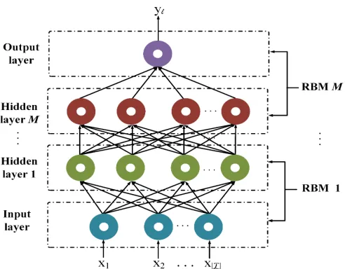
Fig. 2: An example of the DBN framework used in this work.
III. TOTALPOWERMINIMIZATION BYDEEPLEARNING
In this section, we firstly provide a brief description on the framework of the considered deep learning model, namely, DBN. Then, the detailed procedure of the proposed DBN-based approach is developed, which consists of three parts, i.e., data preparation, model training and solution running.
A. Framework of DBN
Prior to developing a specific procedure of the deep learning-based approach, we first briefly introduce the DBN. This model is a representive class of deep learning networks and is capable of capturing the potential information between the input and the output datas [35]. As shown in Fig. 2, the architecture design of the DBN involves an input layer, a set of hidden layers and an output layer, which can be also consid-ered as a series of restricted Boltzmann machines (RBMs). Each RBM consists of a visible layer and a hidden layer. In particular, the neurons between the visible and the hidden layers are fully connected with a certain weight while those neurons within the same layer are disconnected. Furthermore, the first RBM takes the input layer of the DBN as its visible layer and the first hidden layer of the DBN as its own hidden layer; the second RBM takes the hidden layer of the previous RBM as its visible layer and the second hidden layer of the DBN as its own hidden layer; etc. The training procedure for each DBN includes two phases. In the first phase, the RBMs are trained one by one with unsupervised learning to roughly determine the parameters of the DBN. In the second phase, all the parameters of the DBN are fine-tuned with supervised learning according to the back-propagation algorithm. More details of training procedure of the DBNs are given in Section IV-C.
B. Data Preparation Part
To the best of our knowledge, deep learning technique can be considered as a comprehensive tool to derive knowledge from sufficient empirical data. Hence, a large number of
data samples are required to develop a deep learning-based approach to approximate the optimal solution. In our work, we firstly randomly generate channel coefficients hn,k(n ∈
N, k ∈ K) and then employ the genetic algorithm to deal with the optimization problem P1 to determine the optimal solution including the characteristic pattern matrix Q∗, the power allocationP∗and the TS ratio controlα∗. In our work,
the input of the training samplex is composed of the channel coefficients while the outputyis related to the optimal solution that determined by genetic algorithm, which can be more clearly expressed as
x= [h1,1, . . . , h1,K, . . . , hN,1, . . . , hN,K], (18)
y=[q1∗,1, . . . , q1∗,K, . . . , qN,∗ 1, . . . , qN,K∗ ,
P1∗,1, . . . , P1∗,K, . . . , PN,∗ 1, . . . , PN,K∗ , α∗1, . . . , α∗K].
(19)
Note that there areKUEs communicating with the BS via
N REs in the considered system, the vector y is consisted of 2N K +K elements and we need to approximate totally 2N K+Koutput parameters. Hence, we will establish2N K+ KDBNs for all parameters in the next part, which are denoted as DBNℓ (ℓ ∈ 1,2, . . . ,2N K+K). In particular, the set of training samples for DBNℓ is given by {(x, yℓ)}, whereyℓ is theℓth component ofy andℓ∈ {1,2, . . . ,2N K+K}.
C. Model Training Part
With sufficient training samples obtained in the previous part, we now start training the DBN for each parameter to be estimated one by one. For each RBM in DBNℓ, we denotev andh as the vector of the visible layer and the hidden layer, respectively.
The first stage of the training process is unsupervised learning. First of all, the corresponding parameters of the RBM are initialized, including the weights between the visible and hidden layers w, the biases related to the visible layer
bv and the biases associated with the hidden layer bh. Let Φ = {w,bv,bh}. Next, these parameters are updated itera-tively according to the following expression:
Φt+1= Φt+ε
∂logP r(vt)
∂Φt
, (20)
wheretandεdenote the number of iteration and the learning rate in the unsupervised training stage, respectively. Further-more, P r(vt) corresponds to the probability of the visible layer in thetth iterationvt, which can be calculated through the joint probability distribution of the visible and the hidden layersP r(vt,ht). Hence,P r(vt)can be defined as
P r(vt) =
X
ht
P r(vt,ht)
=X
ht
exp (−E(vt,ht))
P vt
P
htexp (−E(vt,ht))
.
(21)
In (21),E(vt,ht)is the energy function related to the RBM, which can be calculated by
E(vt,ht) =−v′twtht−b′v
tvt−b
′
It should be noted that it takes considerably long time to calculate the joint probability distributionP r(vt,ht)according to (21) and (22) due to the high computational complexity. For convenience, an approximate of P r(vt,ht) based on Gibbs sampling has been exploited to tackle this complexity issue in our work.
The second stage of training process is supervised learning. The purpose of this stage is to fine-tune the parameters of DBNℓ based on the output of the training sample, i.e., yℓ. Denotey(ℓi)as the output of theith training sample and thebyℓ(i)
as the output predicted by the DBNℓwith the given inputx(i). The process of fine-tuning can be mathematically formulated as minimizing a loss function namely cross entropy, which is given as
Sℓ=− 1 D
D
X
i=1
yℓ(i)log(yb(ℓi)) + (1−yℓ(i)) log(1−by(ℓi)),
(23) where D is the number of the training samples. In fact, the cross entropy Sℓ is the measure of prediction error of DBNℓ. At the end, the set of parameters Φ is fine-tuned iteratively by the back-propagation algorithm, which can be expressed as follow:
Φt+1= Φt−eε
∂S
∂Φt
, (24)
where eε corresponds to the learning rate of the back-propagation algorithm in the supervised training stage.
D. Solution Running Part
In the solution running part, we first randomly generate the channel gains hn,k(n ∈ N, k ∈ K), and the input layer of DBN is denoted asx= [h1,1, . . . , h1,K, . . . , hN,1, . . . , hN,K]. Then the well-trained DBN networks (DBN1, DBN2, . . . ,
DBN2N K+K) are loaded. With the given inputxand the well-trained DBNℓ, we can compute and predict the output layer of each DBNℓ, denoting asybℓ. Finally, we form the approximate of the optimal solution (including Qb,bPandαb) of the power
minimization problem P1based on the output of each DBN, i.e.,
b
Q=
b
y1 · · · ybK
..
. . .. ...
b
y(N−1)K+1 · · · ybN K
, (25)
b
P=
b
yN K+1 · · · byN K+K ..
. . .. ...
b
y(2N−1)K+1 · · · by2N K
, (26)
and
b
α= [by2N K+1, . . . ,yb2N K+K]. (27)
Up to now, the complete procedure of the proposed DBN-based approach to approximate the optimal solution of the for-mulated transmit power minimization problem is summarized in TABLE I.
INPUT:
The randomly generated channel gains between BS and UEk on REn,hn,k(n∈ N, k∈ K);
OUTPUT:
The approximation of the optimal solution of resource allocation, including the characteristic patternQb, the power allocationPb and the TS ratio controlαb;
1:Generate sufficient training samples{(x,y)}: 2:xcorresponds to the randomly generated channel gains
whiley corresponds to the optimal solution determined by genetic algorithm; the details are given in (18) and (19), respectively.
3:Train the framework of DBNs one by one:
4: set the stopping criteriaǫ1 andǫ2;
5:forℓ= 1 : 2N K+K
6: form= 1 :M
7: initialize the parameters vector Φof themth RBM; 8: Unsupervised learning stage:
9: repeat
10: update the parameters vectorΦaccording to (20); 11: untilkΦt+1−Φtk ≤ǫ1;
12: Supervised learning stage:
13: repeat
14: fine-tune the parameters Φby back-propagation algorithm according to (24);
15: untilkΦt+1−Φtk ≤ǫ2;
16: end
17:end
18:Predict the optimal resource allocation solution:
19:forℓ= 1 : 2N K+K
20: load the well-trained framework of DBNℓ; compute
b
yℓ through DBNℓ with the given channel gains; 21:end
22: form the approximation of the optimal solution according to (25), (26) and (27);
RETURN:Qb,bPandαb;
TABLE I: The complete procedure of the proposed DBN-based approach for total transmit power minimization
IV. SIMULATIONRESULTS
In this section, numerical results are provided to evaluate the performance of our proposed deep learning-based joint resource allocation approach for minimizing the total transmit power. It is assumed that the BS is located in the center of the cellular network and all UEs are randomly distributed within a circle with radius of 300 meters. In other words, the distance between BS and thekth UEdkis randomly generated within the range (0,300). The system bandwidth is assumed to beB= 4MHz. Referring to the typical 3GPP propagation environment in [36], we set the path-loss exponentβ= 3.76. The detailed radio propagation model has been discussed in Section II-A and it is omitted here for brevity. Furthermore, the power conversation efficiency of the EH circuits is set to be
η = 30%; the minimum data rate requirement and harvested power for each UE are assumed to be Rreq = 1Mbit/s and
provided with the corresponding simulation results. In order to construct, train and run the DBNs in our proposed approach, the well-known and powerful off-the-shelf programming tool namelyTensorflow r1.8is used by implementing in thePython 3.6.0 platform.
First, we study the effectiveness of the proposed deep learning-based approach by comparing the predicted result with that obtained by exhaustive search method as well as genetic algorithm. For this study, we consider an example of a system with 4 UEs and 2 REs. The maximum avail-able transmit power is set to be P = 1 W and the noise power on the nth subchannel is assumed to be σ2
n = 0.01 W (n = {1,2}). To the beginning, we randomly generate the channel gains and determine the input of the sample x
based on (18); then solve the problem P1 through genetic algorithm to establish the output of the sample y according to (19). This process is repeated for 10000 times to generate 10000 training samples {(x,y)}. Next, these 10000 samples are used to trained the DBNs. Each DBNℓ consists of five layers, including an input layer x, three hidden layers and an output layer yℓ. The number of neurons in each layer is set to be 8, 64, 128, 128 and 1, respectively. In addition, the learning rates are respectively set to be ε = 0.0001 and
e
ε= 0.0001; the number of training epochs is set to be 3000; and the terminating thresholds are set to be ǫ1 = 1e−3 and
ǫ2 = 1e−3, respectively. In the solution running part, we
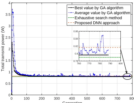
approximate the optimal solution by the well-trained DBNs and the corresponding performance is compared to that of the exhaustive search method and the genetic algorithm. As shown in Fig. 3, the performance obtained by the genetic algorithm is very similar to the one derived by the exhaustive search method. However, it takes about 800 iterations to converge, which requiers a lot of time. In particular, it takes much longer time for the genetic algorithm to converge as the number of UEs and REs increases, and thus it fails to meet the fundamental requirements of ultra-low latency in the communication networks. On the other hand, it can be seen in Fig. 3 that the performance gap between the proposed DBN-based approach and the exhaustive search method is small which is acceptable to some extent. More importantly, it takes less time to approximate the optimal solution through the proposed DBN-based approach, which facilitates to meet the stringent requirement of ultra-low latency.
Next, the performance in terms of the minimum required total transmit power under various system parameters is evalu-ated in Fig. 4. It should be noted that all the simulation results are based on the architecture design of DBNs discussed in the previous simulation, and each result under a certain setting of system parameters is the average of the approximations corresponding to 1000 groups of randomly generated channels. In particular, we assume that the total bandwidth is divided into 4 subcarriers, i.e., N = 4 and Bc = 1 MHz. The noise power in any subcarrier is set to be σ2
n = 0.001/0.01/0.1 W for comparison. As shown in Fig. 4, under the same setting of noise power, the minimum total transmit power approximated by deep learning-based approach is monotonically increasing with the increase in the number of UEs. Furthermore, the trans-mit power consumption always increases with the increase in
Generation
0 100 200 300 400 500 600 700 800
Total tramsmit power (W)
0 0.5 1 1.5 2 2.5 3 3.5 4
Best value by GA algorithm Average value by GA algorithm Exhaustive search method Proposed DNN approach
760 770 780 790 800 0.78
[image:8.612.326.542.61.227.2]0.8 0.82 0.84 0.86
Fig. 3: Performance evaluation of genetic algorithm and the proposed DBN-based approach
Number of UEs
1 2 3 4 5 6 7 8
Minimum total transmit power (W)
0 0.5 1 1.5 2 2.5 3 3.5 4
[image:8.612.321.543.284.450.2]Noise power = 0.001W Noise power = 0.01W Noise power = 0.1W
Fig. 4: Comparison of minimum total transmit power of the proposed approach against different number of UEs with different noise power
the noise power, regardless of the number of UEs. In particular, the relationship between the minimum transmit power and the number of UEs can be approximated as a linear function and the slope of it will increase with the increase in the noise power.
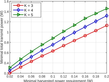
Next, we study the minimum total transmit power estimated by the proposed deep learning-based strategy with different levels of QoS requirements. The minimum data rate require-ment per user is set to vary from 0.2 Mbit/s to 2 Mbit/s while the minimum demand of harvested power is set to vary from 0.02 W to 0.2 W. Furthermore, the number of subcarriers and the noise power are assumed to be N = 4 and σ2
Minimum data rate requirement (Mbit/s)
0.2 0.4 0.6 0.8 1 1.2 1.4 1.6 1.8 2
Minimum total transmit power (W)
0.4 0.6 0.8 1 1.2 1.4
[image:9.612.63.280.60.230.2]K = 3 K = 4 K = 5
Fig. 5: Comparison of minimum total transmit power of the proposed approach with different minimum data rate requirements
Minimal harvested power requirement (W)
0.02 0.04 0.06 0.08 0.1 0.12 0.14 0.16 0.18 0.2
Minimal total transmit power (W)
0.2 0.4 0.6 0.8 1 1.2 1.4 1.6
[image:9.612.322.540.61.230.2]K = 3 K = 4 K = 5
Fig. 6: Comparison of minimum total transmit power of the proposed approach with different minimum harvested power requirements
results confirm and validate the effectiveness of the proposed deep learning-based approach.
Finally, we study the performance comparison in terms of transmit power minimization between the MC-NOMA with PDMA scheme and the OFDMA, SC-NOMA or MC-NOMA with SCMA scheme in SWIPT-enabled systems. The number of UEs is set to be 3/4/5 for comparison. Similarly, all the results are averaged over 1000 trials. Specifically, in OFDMA system, the available bandwidth is equally divided intoKREs and each UE communicates with the BS via one of the REs without any inter-user interference. Furthermore, in the SC-NOMA system, all the UEs communicate with the BS through the entire bandwidth; in the MC-NOMA system with SCMA scheme, the total bandwidth is equally divided into N REs and it allows sparse number of UEs to share the same RE; the MC-NOMA system with PDMA scheme is similar to that with SCMA scheme, but there is no constraint on the number of UEs that share the same RE. The QoS requirements for each UE are the same in different systems. As shown in Fig. 7, both SC-NOMA and MC-NOMA systems are more
Number of users
1 2 3
Minimum total transmit power (W)
0 0.5 1 1.5 2 2.5 3
OFDMA SC-NOMA
[image:9.612.62.281.287.453.2]MC-NOMA with SCMA MC-NOMA with PDMA
Fig. 7: Comparison of minimum total transmit power among OFD-MA, SC-NOOFD-MA, MC-NOMA with SCMA and MC-NOMA with PDMA in SWIPT-enabled systems
power-efficient than OFDMA system and the performance of the MC-NOMA systems are superior to that of the SC-MOMA system. Furthermore, an additional performance gain can be achieved in MC-NOMA system with PDMA scheme, comparing to that with SCMA technique. This is due to the fact that there is no limitation of sparsity in the PDMA scheme so that it is more likely for the UEs to select REs with better channel conditions to communicate with the BS. Hence, this validates and supports the superiority of our proposed scheme as well as the effectiveness of the developed deep learning-based approach.
V. CONCLUSIONS
REFERENCES
[1] G. Chen, J. Tang, and J. P. Coon, “Optimal routing for multihop social-based D2D communications in the Internet of things,”IEEE Internet of Things Journal, vol. 5, no. 3, pp. 1880–1889, Jun. 2018.
[2] P. Wang, J. Xiao, and L. P, “Comparison of orthogonal and non-orthogonal approaches to future wireless cellular systems,”IEEE Veh. Tech. Mag., vol. 1, no. 3, pp. 4–11, Sept. 2006.
[3] Z. Wei, J. Yuan, D. W. K. Ng, M. Elkashlan, and Z. Ding, “A Survey of Downlink Non-orthogonal Multiple Access for 5G Wireless Communi-cation Networks,”[online].Available: https://arxiv.org/abs/1609.01856, Sept. 2016.
[4] Y. Saito, A. Benjebbour, Y. Kishiyama, and T. Nakamura, “System-level performance of downlink non-orthogonal multiple access (NOMA) under various environments,” inProc. IEEE 81st Vehicular Technology Conference (VTC Spring), May. 2015, pp. 1–5.
[5] F. Alavi, K. Cumanan, Z. Ding, and A. G. Burr, “Beamforming tech-niques for nonorthogonal multiple access in 5G cellular networks,”IEEE Trans. on Veh. Tech., vol. 67, no. 10, pp. 9474–9487, Oct. 2018. [6] ——, “Robust beamforming techniques for non-orthogonal multiple
access systems with bounded channel uncertainties,”IEEE Commun. Lett., vol. 21, no. 9, pp. 2033–2036, Sep. 2017.
[7] Z. Ding, X. Lei, G. K. Karagiannidis, R. Schober, J. Yuan, and V. K. Bhargava, “A survey on non-orthogonal multiple access for 5G networks: Research challenges and future trends,”IEEE Journal on Sel. Areas in Commun., vol. 35, no. 10, pp. 2181–2195, Oct. 2017.
[8] L. Dai, B. Wang, Y. Yuan, S. Han, C. I, and Z. Wang, “Non-orthogonal multiple access for 5G: solutions, challenges, opportunities, and future research trends,”IEEE Commun. Mag., vol. 53, no. 9, pp. 74–81, Sept. 2015.
[9] P. Xu and K. Cumanan, “Optimal power allocation scheme for non-orthogonal multiple access withα-fairness,”IEEE Journal on Sel. Areas in Commun., vol. 35, no. 10, pp. 2357–2369, Oct. 2017.
[10] H. Nikopour and H. Baligh, “Sparse code multiple access,” in Proc. IEEE 24th Annual International Symposium on Personal, Indoor, and Mobile Radio Communications (PIMRC), Sept. 2013, pp. 332–336. [11] X. Dai, Z. Zhang, B. Bai, S. Chen, and S. Sun, “Pattern division multiple
access: A new multiple access technology for 5G,” IEEE Wireless Commun., vol. 25, no. 2, pp. 54–60, Apr. 2018.
[12] Z. Wu, K. Lu, C. Jiang, and X. Shao, “Comprehensive study and comparison on 5G NOMA schemes,”IEEE Access, vol. 6, pp. 18 511– 18 519, 2018.
[13] X. Lu, P. Wang, D. Niyato, D. I. Kim, and Z. Han, “Wireless networks with RF energy harvesting: A contemporary survey,” IEEE Commun. Surveys Tuts., vol. 17, no. 2, pp. 757–789, Secondquarter 2015. [14] L. R. Varshney, “Transporting information and energy simultaneously,”
in2008 IEEE Int. Symp. Inf. Theory, Jul. 2008, pp. 1612–1616. [15] X. Zhou, R. Zhang, and C. K. Ho, “Wireless information and power
transfer: Architecture design and rate-energy tradeoff,”IEEE Trans. on Commun., vol. 61, no. 11, pp. 4754–4767, Nov. 2013.
[16] D. W. K. Ng, E. S. Lo, and R. Schober, “Wireless information and power transfer: Energy efficiency optimization in OFDMA systems,”
IEEE Trans. on Wireless Commun., vol. 12, no. 12, pp. 6352–6370, Dec. 2013.
[17] M. Zhang, K. Cumanan, L. Ni, H. Hu Alister G. Burr, and Z. Ding, “Ro-bust beamforming for AN aided MISO SWIPT system with unknown eavesdroppers and non-linear EH model,” in Proc. IEEE Globecom Workshop, Dec. 2018.
[18] M. Zhang, K. Cumanan, and A. Burr, “Secrecy rate maximization for miso multicasting SWIPT system with power splitting scheme,” inProc. IEEE 17th International Workshop on Signal Processing Advances in Wireless Communications (SPAWC), Jul. 2016, pp. 1–5.
[19] J. Tang, D. K. C. So, N. Zhao, A. Shojaeifard, and K. Wong, “Energy efficiency optimization with SWIPT in MIMO broadcast channels for Internet of things,”IEEE Internet of Things Journal, vol. 5, no. 4, pp. 2605–2619, Aug. 2018.
[20] S. Akbar, Y. Deng, A. Nallanathan, M. Elkashlan, and A. Aghvami, “Simultaneous wireless information and power transfer ink-tier
hetero-geneous cellular networks,”IEEE Trans. on Wireless Commun., vol. 15, no. 8, pp. 5804–5818, Aug. 2016.
[21] G. Chen, P. Xiao, J. R. Kelly, B. Li, and R. Tafazolli, “Full-duplex wireless-powered relay in two way cooperative networks,”IEEE Access, vol. 5, pp. 1548–1558, 2017.
[22] Y. Xu, C. Shen, Z. Ding, X. Sun, S. Yan, G. Zhu, and Z. Zhong, “Joint beamforming and power-splitting control in downlink cooperative SWIPT NOMA systems,”IEEE Trans. on Sig. Process., vol. 65, no. 18, pp. 4874–4886, Sept. 2017.
[23] T. N. Do, D. B. da Costa, T. Q. Duong, and B. An, “Improving the performance of cell-edge users in MISO-NOMA systems using TAS and SWIPT-based cooperative transmissions,”IEEE Transactions on Green Communications and Networking, vol. 2, no. 1, pp. 49–62, Mar. 2018. [24] Z. Yang, Z. Ding, P. Fan, and N. Al-Dhahir, “The impact of power
allocation on cooperative non-orthogonal multiple access networks with SWIPT,”IEEE Trans. on Wireless Commun., vol. 16, no. 7, pp. 4332– 4343, Jul. 2017.
[25] N. T. Do, D. B. D. Costa, T. Q. Duong, and B. An, “A BNBF user selection scheme for NOMA-based cooperative relaying systems with SWIPT,”IEEE Commun. Lett., vol. 21, no. 3, pp. 664–667, Mar. 2017. [26] J. Tang, T. Dai, M. Cui, X. Y. Zhang, A. Shojaeifard, K. Wong, and Z. Li, “Optimization for maximizing sum secrecy rate in SWIPT-enabled NOMA systems,”IEEE Access, vol. 6, pp. 43 440–43 449, 2018. [27] D. Zhai, M. Sheng, X. Wang, Y. Li, J. Song, and J. Li, “Rate and energy
maximization in SCMA networks with wireless information and power transfer,”IEEE Commun. Lett., vol. 20, no. 2, pp. 360–363, Feb. 2016. [28] J. Zeng, T. Lv, R. P. Liu, X. Su, M. Peng, C. Wang, and J. Mei, “In-vestigation on evolving single-carrier NOMA into multi-carrier NOMA in 5G,”IEEE Access, vol. 6, pp. 48 268–48 288, 2018.
[29] B. Mao, Z. M. Fadlullah, F. Tang, N. Kato, O. Akashi, T. Inoue, and K. Mizutani, “Routing or computing? the paradigm shift towards intel-ligent computer network packet transmission based on deep learning,”
IEEE Trans. on Comput., vol. 66, no. 11, pp. 1946–1960, Nov. 2017. [30] P. Wang, S. Lin, and M. Luo, “A framework for qos-aware traffic
classification using semi-supervised machine learning in SDNs,” inProc. IEEE International Conference on Services Computing (SCC), Jun. 2016, pp. 760–765.
[31] L. Ghouti, “Mobility prediction using fully-complex extreme learning machines,” in22nd European Symposium on Artificial Neural Networks, Computational Intelligence and Machine Learning, 2014, pp. 607 – 612. [32] B. Bojovic, E. Meshkova, N. Baldo, J. Riihijrvi, and M. Petrova, “Machine learning-based dynamic frequency and bandwidth allocation in self-organized LTE dense small cell deployments,”EURASIP Journal on Wireless Communications and Networking, vol. 2016, 12 2016. [33] D. Tse and P. Viswanath,Multiuser capacity and opportunistic
commu-nication. Cambridge University Press, 2005, pp. 228–289.
[34] L. Lei, D. Yuan, C. K. Ho, and S. Sun, “Power and channel allocation for non-orthogonal multiple access in 5G systems: Tractability and computation,”IEEE Trans. on Wireless Commun., vol. 15, no. 12, pp. 8580–8594, Dec. 2016.
[35] G. E. Hinton, “Deep belief networks,”Scholarpedia, vol. 4, no. 5, p. 5947, 2009, revision #91189.