This is a repository copy of
Implementing Multi-DOF Trajectory Tracking Control System
for Robotic Arm Experimental Platform
.
White Rose Research Online URL for this paper:
http://eprints.whiterose.ac.uk/145488/
Version: Accepted Version
Proceedings Paper:
Ai, Q, Yang, Q, Li, M et al. (2 more authors) (2018) Implementing Multi-DOF Trajectory
Tracking Control System for Robotic Arm Experimental Platform. In: 2018 10th
International Conference on Measuring Technology and Mechatronics Automation
(ICMTMA). ICMTMA 2018, 10-11 Feb 2018, Changsha, China. IEEE , pp. 282-285.
https://doi.org/10.1109/ICMTMA.2018.00075
(c) 2018, IEEE. This is an author produced version of a paper published in 2018 10th
International Conference on Measuring Technology and Mechatronics Automation.
Uploaded in accordance with the publisher's self-archiving policy. Personal use of this
material is permitted. Permission from IEEE must be obtained for all other uses, in any
current or future media, including reprinting/republishing this material for advertising or
promotional purposes, creating new collective works, for resale or redistribution to servers
or lists, or reuse of any copyrighted component of this work in other works.
[email protected] https://eprints.whiterose.ac.uk/ Reuse
Items deposited in White Rose Research Online are protected by copyright, with all rights reserved unless indicated otherwise. They may be downloaded and/or printed for private study, or other acts as permitted by national copyright laws. The publisher or other rights holders may allow further reproduction and re-use of the full text version. This is indicated by the licence information on the White Rose Research Online record for the item.
Takedown
If you consider content in White Rose Research Online to be in breach of UK law, please notify us by
Implementing Multi-DOF Trajectory Tracking Control System for Robotic Arm
Experimental Platform
Qingsong Ai
1, 2, Qifan Yang
1, 2, Min Li
1, 2, Xiaorong Feng
1, 2, Wei Meng
1, 2*1School of Information Engineering, Wuhan University of Technology, Wuhan, China, 430070
2Key Laboratory of Fiber Optic Sensing Technology and Information Processing, Ministry of Education, Wuhan, China, 430070
*Corresponding author email: [email protected]
Abstract—To implement the control system of a multi-DOF robotic manipulator (Dobot), the robot dynamics, trajectory planning algorithm and motion control strategy are studied for designing the trajectory tracking control system. In this paper, the hardware and software of Dobot magician control system are designed. The hardware mainly includes STM32 controller. The software part mainly builds the host computer display interface, completes the protocol communication between the robot manipulator and the PC, so as to realize the trajectory tracking control of the robot manipulator and implement the track-following in real time. The experimental results show that the control system can accurately track the trajectory of robotic manipulator with a certain degree of real-time and stability.
Keywords- robotic manipulator trajectory tracking control trajectory planning control systems
I. INTRODUCTION
Under the trend of AI, all countries are innovating and developing their own robot technology. Among them, the research technology in Japan, Korea, United States and Germany is more advanced [1]. With the continuous development of China's economy and technology in recent years, the research in the field of investment is more increasing, and gradually developed its Chinese characteristics of the robot technology, and Chinese industry leaders began to build intelligent digital factory [2]. At the same time, with the rise of service robot, manipulator is also into our daily life, in recent years there have been a number of low cost, small, "desktop" arm products, gradually, people began to hope that convenient intelligent manipulator can walk into our daily life [3].
Robot products are moving in the direction of high precision, high intelligence, strong controllability and high performance [4]. There are a number of domestic and foreign research institutes, Delingon gives a detailed introduction of the desktop robot [5] hardware circuit. Yongkui Man uses three degrees of freedom robot manipulator to study the accuracy of the writing, through the interpolation algorithm and coordinate transformation method [6] to implement different handwritten calligraphy. KW Kwok did a great deal of work on a five-degree-of-freedom manipulator and added machine vision to correct errors in writing in real time. Kim S K studied pen writing and writing intensity [7].
A mature manipulator will include mechanical structures, sensor applications, hardware facilities, related driving software [8], and intelligent control algorithms. And the robot trajectory planning is mainly to study the end of the robot path motion and movement in the process of moving speed and acceleration. Trajectory planning should not only consider what kind of curve the motion path, but also consider the time factor, trajectory planning, so that makes the manipulator
moves fast, accurately and steadily. At the same time, the kinematics control and dynamic control need to be studied, so that the whole manipulator control system has better tracking motion and stronger anti-interference ability [9].
In this paper, we mainly study on the drawing of multi-degree-of-freedom robotic manipulator, mainly on the analysis of kinematics, trajectory planning and control software design of robotic arm and finally realize the function of arm painting. The rest of this paper is arranged as follows: Section II presents Robot manipulator system. Robotic trajectory tracking control is described in Section III. Section IV draws the conclusion of the paper.
II. ROBOTMANIPULATORSYSTEM
The tracking system includes robot manipulator, PC, STM32 processor, touch screen device. The upper monitor is used to accept and judge the check command, achieving communication with the robot manipulator in the VS to obtain the real-time coordinates data [10].Then, through the coordinate mapping, the data is displayed in coordinate curve in real time.
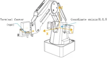
The STM32 processor is the core of the tracking control system which includes touch screen driver initialization, touch signal capture, data processing and transformation, the corresponding filter processing. First of all, the robot is initialized, and then according to the Dobot robot communication protocol PTP mode, the data in accordance with the frame header, parity and other protocols was sent out. The robot manipulator is used as the actuator to analyze the position coordinates, and then execute the corresponding actions and motion, so as to achieve the purpose of tracking [11]. In order to further study and understand the structure of robot manipulator, the actual coordinate diagram are shown in Figure 1[12, 13].
[image:2.595.337.513.540.642.2]
screen module. The software module include the design of PC-side interface, the interpretation and sending of protocol instructions and the drawing of the real-time coordinate position constitutes.
A. The hardware
The hardware of robot manipulator tracking system is composed of robot manipulator system, STM32 minimum system and EU-TFT3.2 color screen module. The STM32 minimum system, as our core processor, uses a series of stm32f10ze chips, 32-bit ARM microcontrollers. The EU-TFT3.2 color screen module input is a hardware device that collects the touch button signal and transmits the signal to the STM32 core processor in the form of level for processing. The robot manipulator system with the core processor accepts and executes external commands and can control the stepper motors through PC platform (Dobot Studio), Wi-Fi Bluetooth APP, the Leap motion Somatosensory Controller and many other ways. The hardware composition of tracking system is shown in Figure 2.
(a) The hardware design block diagram
(b) The hardware design block diagram
Figure 2. (a) The hardware design block diagram and (b) The hardware design block diagram.
B. The software
The software of the robot manipulator tracking system mainly includes two parts: the design of the upper computer interface and the design of the tracking system. The tracking system uses the STM32 microprocessor as the core to complete data acquisition and filtering, communication with the Dobot manipulator, automatic drawing, touch writing algorithm and handwriting screen driver; the upper computer interface includes the communication protocol and API interface to
[image:3.595.338.502.87.216.2]realize the data communication between PC and robot arm and the curve of the drawing [14].
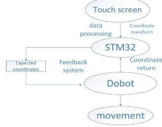
Figure 3. The block diagram of manipulator control system The purpose of controlling of Dobot manipulator is to control the position of the end arm to consistent with the desired trajectory. In order to achieve trajectory tracking, it is necessary to establish the kinematics and dynamics model of the Dobot manipulator. The specific feedback control process is shown in Figure 3 [15].
Dobot manipulator is divided into two sports modes: one is point-to-point movement, that is, PTP mode, such as suction movement, reciprocate up and down, from A to B; the other is continuous Trajectory movement, that is, CP mode, such as continuous trajectory drawing. The kinematic model of the robot manipulator calculates the movement angles of the corresponding joints according to the coordinates of the target so as to obtain the coordinates of the ends of the robot manipulator [16]. Dynamic control is actually to control the actual dynamic motion of the robot manipulator. In the actual process of robot manipulator movement, the effective control algorithm needs to be considered to ensure the stability of robot manipulator control system and the accuracy of trajectory tracking [17].
III. ROBOTICTRAJECTORYTRACKINGCONTROL
The design of the robot's tracking system includes the software part and handwritten trajectory control, the software design includes automatic drawing of robotic tracking system and the trajectory control movement algorithm. Handwritten trajectory control section mainly introduces the system's instruction and the handwriting effects.
A. Robotic Arm Path Planning
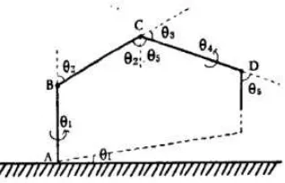
Before designing the trajectory of the robot, the coordinate transformation method in robotics is introduced to establish the functional relationship between the corresponding XYZ and the rotation angle of the joint. Because the connecting rod of the robot arm can be regarded as rigid, a simple point-to-point motion model is created, when
4=0 , the correspondingcoordinates of D can be uniquely determined by
1, ,2 3, andFigure 4. Two-dimensional DOF point-to-point geometric model
Where
1
2
3
=90 arctan 90 2
x y
(1)
2 2
arctan z AB
x y
D L
D D
(2)
2 2 ( )2
arccos x y z AB
BC
D D D L
L
(3)
The fast tracking algorithm and the fitting of the continuous trajectories added during the actual movement, which will made the robot move more gentle and quickly. First, the coordinate curve of the movement is discretized, define
( ), ( ), ( ),
x s s y y s z z s a s b , a s s 1 2 sn b,
then controlling the robot move to the starting point at a faster speed, calculating the connection distance from this point Di1
to the next target point Di, and obtain the real-time coordinates of the fingertip. Using the error between the expected trajectory and the actual trajectory, the position of the tip of the robot is updated in real time. By constantly correcting the placement of continuously updated curves, the motion of the curve is fitted to make the manipulator more comfortable to complete the task.
B. Robotic Tracking Algorithm
The drawing of straight lines and arcs is the key problem to be solved in the drawing of a robot arm. It is determined whether the trajectory drawn from the current point to the next point is the same as expected.
When drawing a circle, using the ticking clock in the STM32 processor to send a position command every 20ms, the position coordinates of which satisfy the (4) with a radius of 40mm.
2 2 2
(x a ) (y b ) r (4)
The value of x increases 0.1 every 20ms, the value of y takes the coordinate value corresponding to the (5):
2 2
( ( ) )
y sqrt r x a (5)
The coordinate values of the micro-cells are packaged and sent to the manipulator according to the protocol header, the payload length, the payload frame and the format data of the verification, so that the robot performs the corresponding position action. Then a complete circle is divided into n micro-elements step by step to achieve the robot arm graphics, and we can reduce error by adding the number of micro-elements.
When drawing heart-shaped graphics, define the intermediate variable t, the value of x increases 0.01 every 20ms. The parametric equation is shown in (6):
3
2 3 4
16sin
(13cos 5cos 2cos cos )
x a t
y b t t t t
(6)
(a)Circle (b) Heart-shaped Figure 5. The experimental results
And then sent the micro-yuan position package to the robot arm, the equation can also be multiplied by a factor to achieve the size of the actual heart-shaped. The experimental results are shown in Figure 5. It can be seen from the figure that the graph drawn by the robot is very close to the actual graph and the trajectory written is very smooth, indicating that the algorithm mentioned above is correct.
C. Gesture Control in the Touch Screen
Initializing the TFT-LCD screen and the Dobot manipulator in the main functions, and then continuously detect the touch button coordinates, after smoothing filter processing, the coordinates can be get and displayed on the TFT touch screen, so that a gesture drawing function can be achieved [18]. The touch screen coordinates is transformed into XYZ values of the Dobot arm and sends the commands to the arm in PTP mode. At this moment, the z-axis of the robot is controlled to move up and down in the Z coordinate, and a small area is drawn on the touch screen with blue and red, and write "Z +" and "Z-" with a black background inside the area. If a touch signal is detected in the blue and red areas, we raise / lower some coordinates to complete the action of lifting and dropping the pen. The code needs to be done related to the following step:
a)Touch Data Sampling Collection .
b)Ddata filtering process.
c)Pprocessing data into coordinate values.
d)Ccoordinate mapping.
[image:4.595.217.546.196.360.2]Figure 6. Touch screen writing control
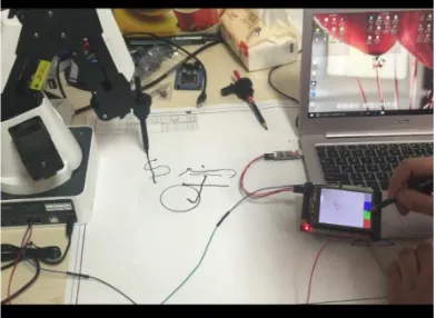
[image:5.595.36.290.336.422.2]The touch screen writing control results are shown in Figure 6. And the experimental results are shown in Figure 7, the manipulator's trajectory tracking by arm writing drawing is presented, while the characters are drew on the STM32 touch screen, the manipulator can draw a picture of the same size tracked the corresponding characters trajectory in the paper in a very short time, then the result diagram’s position coordinates of the manipulator are collected, and the tracking is completely displayed in the upper computer interface.
Figure 7. The overall effect of the system
Finally, the system has achieved the effect of the real-time trajectory display. It can be clearly seen from the PC interface that the manipulator well completes the position instruction we sent to him by STM32, to produce a great result effect of trajectory control and trajectory tracking.
IV. CONCLUSION
This article describes a robotic trajectory tracking control system that verifies trajectory tracking accuracy by writing. First of all, the related dynamic model is established, and the trajectory planning algorithm is researched. Through the establishment of the host computer display interface, the protocol communication between the robot and the PC is completed, and the effect of writing and drawing (circular, heart-shaped, square, etc.) of the robot with the touch screen is achieved. The experimental results show that the robot arm can write and draw correctly, and the upper computer interface of the control system can display the real position of the end of the arm in the writing process in real time, which has real-time and good stability.
In the actual application of research work, we can accomplish some sophisticated actions by manipulating the
manipulator. And the relevant trajectory algorithm research and control strategy can be applied to the actual large-scale industrial robots for more sophisticated operation and perfect strategy control.
ACKNOWLEDGMENT
This research is supported by National Natural Science Foundations of China (under grants No. 51475342, 51705381)
REFERENCES
[1] S. Kashem, and H. Sufyan, “A novel design of an aquatic walking robot having webbed feet,” International Journal of automation and Computing, vol. 14, pp. 576-588, 2017.
[2] T. Yang, W. Zhang, and Q. Huang, et al., “A Smooth and Efficient Gait Planning for Humanoids Based on Human ZMP,” Robot, vol. 39, pp. 751-758, 2017.
[3] X. Chen, and F. Gao, “Energy Expenditure of Trotting Gait under Different Gait Parameters,” Chinese Journal of Mechanical Engineering: English version, vol. 30, pp. 943-950, 2017.
[4] N. Kodaira, "Expected innovation in industrial robots," Advanced Robotics, vol. 30, pp. 1088-1094, 2016.
[5] D. Dong, “Research and design of teaching robot based on graphical programming,” Chongqing: Shanghai Jiaotong University, 2011. [6] Y. Man, C. Bian, and H. Chao, et al., “A kind of calligraphy
robot,” International Conference on Information Sciences and Interaction Sciences IEEE, pp. 635-638, 2010.
[7] S. K. Kim, et al. “Robotic handwriting: Multi-contact manipulation based on Reactional Internal Contact Hypothesis,” IEEE/RSJ International Conference on Intelligent Robots and Systems IEEE, pp. 877-884, 2014.
[8] L. Wang, and J. Cao, “A look-ahead and adaptive speed control algorithm for high-speed CNC equipment,” International Journal of Advanced Manufacturing Technology, vol. 63, pp.705-717, 2012. [9] A. Vaz, “Robot trajectory planning with semi-infinite programming,”
European Journal of Operational Research, vol. 153, pp. 607-617, 2004.
[10] A. Safavi, and MH. Zadeh, “Teaching the User by Learning from the User: Personalizing Movement Control in Physical Human-robot Interaction,” IEEE/CAA Journal of Automatica Sinica, vol. 4, pp. 704-713, 2017.
[11] P. Sun, and Z. Yu, “Tracking control for a cushion robot based on fuzzy path planning with safe angular velocity,” IEEE/CAA Journal of Automatica Sinica, vol. 4, pp. 610-619, 2017.
[12] D. Wilcher, “Arduino Robotic Controllers,” Springer Berlin, 2013. [13] “Modeling and Analysis of a Trajectory-Based Stability,” International
Journal of Systems & Control, 2006(1).
[14] W. Dong, W. Huo, and S. K. Tso, et al., “Tracking control of uncertain dynamic nonholonomic system and its application to wheeled mobile robots,” IEEE Transactions on Robotics & Automation, vol. 16, pp. 870-874, 2000.
[15] M. Roozegar, M. J. Mahjoob, and M. Jahromi, “Optimal motion planning and control of a nonholonomic spherical robot using dynamic programming approach: simulation and experimental results,”
Mechatronics, vol. 39, pp. 174-184, 2016.
[16] S. Bhattacharyya, A. Konar, and D. N. Tibarewala, “Motor imagery and error related potential induced position control of a robotic arm,”
IEEE/CAA Journal of Automatica Sinica, vol. 4, pp. 639-650, 2017. [17] M S. Mahmoud, and M. T. Nasir, “Robust control design of wheeled
inverted pendulum assistant robot,” IEEE/CAA Journal of Automatica Sinica, vol. 4, pp. 628-638, 2017.