SMART AUTOMATED HOME
MEGAT IZZUDDIN BIN MEGAT AB MANAP
“I hereby declared that I have read through this report and found that it has comply the partial fulfillment for awarding the degree of Bachelor of Electrical Engineering
(Control, Instrumentation & Automation)‖
Signature : ………
Supervisor’s Name : Jurifa Bt Mat Lazi
SMART AUTOMATED HOME
MEGAT IZZUDDIN BIN MEGAT AB MANAP
This Report Is Submitted In Partial Fulfillment of Requirements for the Degree of Bachelor in Electrical Engineering (Control, Instrumentation & Automation)
Faculty of Electrical Engineering Universiti Teknikal Malaysia Melaka
DECLARATION
―I hereby declared that this report is a result of my own work except for the excerpts that have been cited clearly in the references.‖
Signature : ………
Name : MEGAT IZZUDDIN BIN MEGAT AB MANAP
DEDICATION
ACKNOWLEDGEMENTS
First of all, I would like to express my thankfulness to Allah S.W. T who has given me the strength, knowledge and capability to implement and complete my Projek Sarjana Muda and also to complete this report.
I would like to express my highest and foremost gratitude to my project supervisor, Puan Jurifa Bt Mat Lazi for her guidance, help and advices to complete this project. Next, I would like to thank Malaysian Coal Integrated Engineering Services (MCIE), the company which I had my industrial training attachment with for their sponsorship of equipments and devices which I used for my project. I would also like to thank the Faculty of Electrical Engineering (FKE), Universiti Teknikal Malaysia Melaka (UTeM) for giving me the opportunity to implement and complete my project.
ABSTRACT
ABSTRAK
TABLE OF CONTENTS
CHAPTER CONTENTS PAGE
TITLE PAGE i
DECLARATION ii
DEDICATION iii
ACKNOWLEDGEMENTS iv
ABSTRACT v
ABSTRAK vi
TABLE OF CONTENTS vii
LIST OF FIGURES xiii
LIST OF TABLES xv
LIST OF APPENDICES xvi
LIST OF ABBREVIATIONS xvii
1 INTRODUCTION
1.1 Project Background 1
1.2 Problem Statement 3
1.2.1 General Problem Statement 3
1.2.2 Detailed Problem Statement 4
1.3 Project Objective 4
1.4 Project Scope 5
2 LITERATURE REVIEW
2.1 Case study 7
2.1.1 The Home Depot Smart Home 7
2.1.2 The purpose of building the Home Depot Smart 8 Home at Duke
2.1.3 The Duke Smart Home Program 9
2.1.4 Benefits of the Duke Smart Home Program 10
2.1.5 Accessibility in The Home Depot Smart Home 12
2.1.6 Cooling Systems for The Home Depot Smart 12
Home
2.1.7 Daylighting 12
2.1.8 Fire Safety 13
2.1.9 Geothermal Pump 13
2.1.10 Indoor Air Quality Monitoring 13
2.1.11 Leadership in Energy and Environmental Design 13 (LEED)
2.1.12 Media-on-Demand 14
2.1.13 Photovoltaic System Design 14
2.1.14 Protecting Public Health – UV Disinfection 14 of Drinking Water
2.1.15 Recycling 15
2.1.16 Retractable Roof 15
2.1.17 RFID Technology 15
2.1.18 Security 16
2.1.19 Soundproofing and Acoustic Suggestions 16 2.1.20 Water Catchment, Purification/ Rainwater 16
Harvesting
Noise Filtering
2.1.22 Facial Recognition 17
2.1.23 Advanced HVAC Control and Artificial 17
Intelligence Controllers
2.1.24 LED Lighting 17
2.1.25 Residential Piezoelectric Energy Sources 17
2.1.26 Sensor Platform 18
2.1.27 Shower Heat Recovery 18
2.1.28 Sleep Monitoring 18
2.1.29 Home Automation 19
2.2 Conclusion 19
3 METHODOLOGY
3.1 Overview 20
3.1.1 Literature review 20
3.1.2 Design the modules and circuits 20
3.1.3 Simulate circuits 20
3.1.4 Redesign circuits 21
3.1.5 Purchase components 21
3.1.6 Assemble circuits 21
3.1.7 Test operation 21
3.1.8 Troubleshoot 21
3.1.9 Assemble the modules 22
3.1.10 Test operation 22
3.1.11 Improvements, modifications and additions 22
3.1.12 Analysis 22
3.1.13 Connect the assembled modules 22
3.1.14 Test operation 23
3.2 Flowchart 24
3.3 Gantt chart 26
4 PROJECT BACKGROUND
4.1 Introduction 27
4.1.1 Smart Home 27
4.1.1.1 Functions of smart home system 28
4.1.1.2 Benefits of smart home system 29
4.2 Project Background 30
4.2.1 Indoor Lighting 30
4.2.1.1 Overview 30
4.2.1.2 Design 30
4.2.1.3 Circuit 32
4.2.1.4 Hardware and software 33
4.2.2 Outdoor Lighting 34
4.2.2.1 Overview 34
4.2.2.2 Design 34
4.2.2.3 Circuit 35
4.2.2.4 Hardware and software 38
4.2.3 Indoor Ventilation 39
4.2.3.1 Overview 39
4.2.3.2 Design 39
4.2.3.3 Circuit 41
4.2.3.4 Hardware and software 42
4.2.4 Garbage disposal 44
4.2.4.1 Overview 44
4.2.4.2 Design 45
4.2.4.4 Hardware and software 46
4.2.5 Garage and car park 50
4.2.5.1 Overview 50
4.2.5.2 Design 50
4.2.5.3 Circuit 53
4.2.5.4 Hardware and software 53
4.2.6 Events alert 58
4.2.6.1 Overview 58
4.2.6.2 Design 58
4.2.6.3 Circuit 59
4.2.6.3.1 Water Level Sensor 59
4.2.6.3.2 Heat Sensing 61
4.2.6.3.3 Smoke Sensor 62
4.2.6.3.4 Buzzer Interval 64
4.2.6.4 Hardware and software 65
4.2.7 Garden Management 68
4.2.7.1 Overview 68
4.2.7.2 Design 68
4.2.7.3 Circuit 69
4.2.7.4 Hardware and software 70
4.3 Components 71
4.3.1 Programmable Logic Controller (PLC) 71
4.3.1.1 Introduction to PLC 71
4.3.1.2 Features of PLC 72
4.3.1.3 Comparing PLC with other control 73 systems
4.3.1.4 Programming 75
4.3.2 Omron ZEN 76
4.3.2.2 Programming 76
4.3.2.3 Functions 77
4.3.2.4 Expansion 77
4.3.2.5 Support software 78
4.3.3 Integrated circuit (IC) 79
4.3.3.1 Introduction 79
4.3.3.2 History of ICs 79
4.3.3.3 Advantages of ICs 80
4.3.3.4 Popularity of ICs 80
4.3.3.5 Classifications of ICs 80
4.3.4 555 Timer IC 81
4.3.4.1 Introduction 81
4.3.4.2 Inputs of 555 83
4.3.4.3 Outputs of 555 84
4.3.4.4 555 Astable 84
4.3.5 741 Op-Amp IC 85
4.3.5.1 Introduction 85
4.3.5.2 Definition of 741 pin functions 86
4.4 Project Costs & Expenses 87
5 RESULT & DISCUSSION
5.1 Result 89
5.2 Discussion 90
5.2.1 Problems & Challenges 90
6 CONCLUSION & RECOMMENDATIONS
6.1 Recommendations 92
REFERENCES 94
APPENDICES 95
LIST OF FIGURES
FIGURE TITLE PAGE
1.1 Block Diagram of control system using PLC and IC 1
2.1(a) The Home Depot Smart Home 7
3.2 Project flow chart 24
3.3 Gantt chart 26
4.1(a) A smart home system 28
4.2.1(a) Block diagram for Indoor Lighting 30
4.2.1(b) Assembled circuit for the Indoor Lighting 32
4.2.1(c) Light dimmer circuit using PWM control method 32
4.2.2(a) Block diagram for Outdoor Lighting 34
4.2.2(b) Assembled circuit for the Outdoor Lighting 35
4.2.2(c) IC 555 Timer pin allocations 35
4.2.2(d) Internal circuit for IC 555 Timer 36
4.2.2(e) Light/dark sensing circuit for Outdoor Lighting 36
4.2.3(a) Block diagram for Indoor Ventilation 39
4.2.3(b) Wheatstone Bridge 40
4.2.3(c) Assembled circuit for Indoor Ventilation 41
4.2.3(e) 12VDC CPU fan rated at 0.13A 43
4.2.3(f) Temperature display unit 43
4.2.4(a) Block diagram for garbage disposal 45
4.2.4(b) Concept diagram for garbage disposal 45
4.2.4(c) Ladder diagram for overall Garbage Disposal module 48
4.2.4(d) Inductive proximity sensor used for platform position 48
4.2.4(e) AC Synchronous motor used for platform rotation 49
4.2.5(a) Concept diagram for garage and car park 50
4.2.5(b) Block diagram for garage and car park 51
4.2.5(c) Limit switch and triangular marker 52
4.2.5(d) Rotating platform 52
4.2.5(e) Optical distance sensor 54
4.2.5(f) Ladder diagram for garage door 56
4.2.5(g) Ladder diagram for rotating platform 57
4.2.6(a) Block diagram for Events Alert 58
4.2.6(b) Assembled circuit for Water Level Sensor 59
4.2.6(c) Water Level Sensor circuit for Events Alert 60
4.2.6(d) Assembled circuit for Heat Sensing 61
4.2.6(e) Heat Sensing circuit for Events Alert 61
4.2.6(f) Assembled circuit for Smoke Sensor 62
4.2.6(g) Smoke Sensor circuit for Events Alert 63
4.2.6(h) Assembled circuit for Buzzer Interval 64
4.2.6(i) Buzzer Interval circuit for Events Alert 64
4.2.7(a) Block diagram for Garden Management 68
4.2.7(b) Ultrasonic pest repellant circuit for Garden Management 69
4.3.1(a) PLC and input/output arrangements 71
4.3.1(b) Control Panel with PLC 72
4.3.2(a) Multi function and space saving features 76
4.3.2(b) Programming the Omron ZEN 76
4.3.2(c) Expansion units 77
4.3.3 Integrated circuit 79
4.3.4(a) Actual pin arrangements 81
4.3.4(b) Example circuit symbol 83
4.3.4(c) 555 Astable output, a square wave 84
4.3.4(d) 555 Astable circuit 85
4.3.5 741 Op Amp pin functions 86
5.1 Completed project 89
LIST OF TABLES
TABLE TITLE PAGE
4.3(a) Purchased hardware total cost 87
4.3(b) Sponsored hardware total cost 88
LIST OF APPENDICES
APPENDIX TITLE PAGE
A UTeMEX poster 96
LM555 Single Timer datasheet 97
LM741 Operational Amplifier datasheet 109
Optical distance sensor datasheet 116
LIST OF ABBREVIATIONS
ABBREVIATIONS MEANING
CCTV Closed circuit television
DC Direct current
AC Alternating current
IC Integrated circuit
LCD Liquid crystal display
LDR Light dependant resistor
LED Light emitting diode
PLC Programmable logic controller
PIC Programmable interface controller
PWM Pulse Width Modulation
NO Normally open
NC Normally close
CHAPTER 1
1.1 Project Background
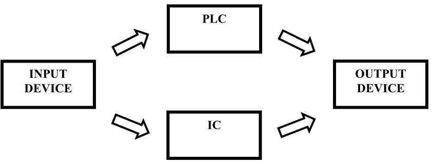
[image:20.612.88.509.204.362.2]This chapter provides the necessary background for this project, which explains the basic principle of PLC and IC control system.
Figure 1.1: Block Diagram of control system using PLC and IC
To create a control system, it must have 3 basic components which are input, process and output. The process consists of the PLC and IC which acts as input signal processing device to control the output. A brief introduction to the concept of application is given to provide basic understanding of this project.
The input device comes in the form of ordinary on/off limit switches, push buttons, variable resistors, photo-electric sensors, proximity sensor, light dependent resistors (LDR) and thermistors. These devices provide the activation signal in the form of analog or digital signal to the control unit.
The controller part which is the PLC and the IC acts as the primary control unit for this project. In this system, the PLC controller used is the Omron ZEN micro PLC unit. The input signals are transmitted digitally into the PLC and an appropriate
INPUT DEVICE
PLC
IC
―decision‖ will be made by the PLC according to the programmed ladder logic diagram. The PLC will then produce a digital signal in the form of relay output.The PLC is chosen over PIC to provide control for this project due to its multiple inputs and output arrangements and also its easy and user friendly programming using ladder logic diagram. The key feature for the PLC that is used is the built in daily, weekly and monthly timer capability which provides useful control for time controlled operation.
The IC is used for analog signal processing which involves decision making through logic gates combination and comparing two or more sets of input signals. There are two main advantages of ICs over discrete circuits which is the cost and performance. Cost is low because the chips, with all their components, are printed as a unit by photolithography and not constructed a transistor at a time. Performance is high since the components switch quickly and consume little power, because the components are small and close together.
For this project, the control is divided into two control devices which are the PLC and the IC. The purpose for this design is to fully utilize the advantages of both devices. The PLC has the advantage of easy programming, multiple relay outputs and enables systematic & organized wiring to be implemented. The IC on the other hand has the advantage of miniature size, low costs and provides tons of function according to the circuit it is connected. By combining two forms of these widely used devices, a good and reliable control system can be created to cater the project’s needs.
The output device will be in the form of relays, buzzer, DC motors, tweeter, lights, LEDs and fans. These devices receive activation signal from the PLC, IC or directly from the input device and perform various functions including illumination, cooling and etc.
This project like all others is created to solve problems that we humans encounter everyday. Upon completion of this project, the problems that we face will hopefully be solved or at least reduced. To make it easier to explain regarding the problem statements, they are divided into two parts, which is general aspect and detailed according to the system arrangements
1.2.1 General Problem Statement
There is no training kit that emphasizes the combination between PLC and electronics based circuits.
Most training kit available focuses on industrial system but not home automation system.
Available home automation has limited control over devices/system and costly.
1.2.2 Detailed Problem Statement
For the indoor lightings, the lights switches are located far away, not easily to access locations and the lights cannot be dimmed.
The outdoor lights needs to be turned on and off manually at day & night and sometimes the occupant forgot to turn them off. This causes wastage in electricity bills.
The temperature inside (indoor) are hot and unpleasant. The hot/warm air is trapped inside house due to poor ventilation
The occupant missed the weekly garbage collection time and the garbage spilled when bringing it outside the house. Furthermore, the odor from the garbage attracts flies & disease.
Plants at the garden die due to lack of watering and the gardens are infected by pests.
Accidentally hit the garage wall/children while reversing the vehicle and sometimes the occupant forgets to close the garage door
House does not have fire and flood warning system.
1.3 Project Objective
The objective of this project is to design & construct a control system
which consists of home automation and lighting control that can be used for various purpose especially teaching & learning and home application.
The lighting control is used to control the illumination and brightness for
1.4 Project Scope
Scope and limitations for this project:
Design and construction of a control system consist of home automation and lighting control.
Constructed using PLC, Electronic circuits, DC motors, sensors, switches, relays etc.
The model design & construction consists of small scale model that represents the connection and function of the system.
System powered by DC source through switching power supply and voltage regulators.
Lighting
i. Indoor
ii. Outdoor
Home automation
i. Ventilation (Indoor) ii. Garbage disposal
iii. Garden management
1.5 Project Advantages & Benefits
There are many advantages and benefits for the implementation of this
project. A simple yet effective lighting control and home automation system is created. The control and automation system is easy to troubleshoot for problems and easy to improve or upgrade the system in the future. The system is also user friendly and safe that is usable by all ages including children as a system should be easy to control and handled by everyone. The system creates a low cost home automation system that is affordable by everyone so that everyone can experience the advancement in modern technology.
The system also makes efficient use of electricity by optimizing and minimizing the usage hours of lightings and ventilations system through automatic turn on and turn off system. Electricity bills and power wastage will be reduced and ensures a prolonged life span of electrical devices through optimized working hours. Lights and fans turn on only when needed.
CHAPTER 2
LITERATURE REVIEW
2.1 Case Study
The case study for this project is based on the Home Depot Smart Home constructed by Duke's Pratt School of Engineering.
2.1.1 The Home Depot Smart Home
[image:26.612.170.442.488.665.2]The Home Depot Smart Home is a 6,000 square foot live-in research laboratory operated by Duke's Pratt School of Engineering. The Home Depot Smart Home, part of a Duke Smart Home Program, creates a dynamic "living laboratory" environment that contributes to the innovation and demonstration of future residential building technology. The central concept of this project is our belief that smart homes can improve that quality of life for people of all ages and incomes.
The Home Depot Smart Home provides students at Duke's Pratt School of Engineering, Trinity School of Arts and Sciences and Nicholas School for the Environment and Earth Sciences with an opportunity for practical hands- on engineering outside of the classroom in a living and learning community. In addition, the partnering with industry to strengthen the residential market for integrated technology, and helping homeowners make their own ideas for smart homes a reality.
The goals for the residents of The Home Depot Smart Home are to: a) Commit to and explore an energy efficient lifestyle,
b) Compare, use and develop smart and sustainable technology, and
c) Provide insight to homeowners for "do-it-yourself" technology integration and control.
2.1.2 The purpose of building the Home Depot Smart Home at Duke
experiences of other university Smart Home projects. The long term goal is to influence the national market for residential technology integration, and to help educate homeowners about the latest technologies.
2.1.3 The Duke Smart Home Program
The Duke Smart Home Program is a research-based approach to smart living sponsored by the Pratt School of Engineering. Primarily focused on undergraduates, the program encourages students from different academic disciplines to form teams and explore smart ways to use technology in the home. The emphasis on 'smart' means finding the best technology answer for a particular problem--not just finding the high tech solution or the latest gadget on the market. This approach naturally leads students to identify 'gaps' in the marketplace--problems that just aren't being addressed through commercially available technology. These gaps then become the basis for exploration.
The Duke Smart Home Program fosters strong relationships with industry through collaborative projects, tours and interviews, guest lectures and internships. Hopefully, to not only strengthen the market for integrated technology, but to also help homeowners make their own ideas for smart home a reality. The central concept of this project is the belief that smart homes can improve that quality of life for people of all ages and incomes.
The Duke Smart Home Program provides students with outlets for: a) Hands-on technology exploration and optimization,
b) Project management, team building and design experience, c) Study of technology adoption and design refinement,
d) Study of product marketability, economics and practical engineering aspects of product design, and exploring the gap between commercial versus consumer technology and shaping the future of smart residential living.
2.1.4 Benefits of the Duke Smart Home Program
a) Provides Practical Design Experience - One of the biggest challenges for universities is involving students in hands-on engineering experiences early in the curriculum. Design and application of design is the most fundamental skill of engineering, yet at many universities, exposure to design is often limited until senior year. Multiple Duke engineering classes already are using data from the various Smart Home projects to teach students in tangible ways. b) Project Management and Communications Experience - Students in the
c) Exposure to Cross-disciplinary teamwork - The Home Depot Smart Home project is inherently cross-disciplinary--incorporating civil and environmental engineering, electrical and computer engineering, materials science and mechanical engineering and even biomedical engineering. The project also draws on computer science, environmental science and human factors disciplines. Project teams are specifically designed to bridge the gap across the disciplines and give students exposure and experience in field outside their own specialties. With all these disciplines involved, student teams gain a unique support network unavailable to most entrepreneurs and this will promote the future success of our students.
d) Intellectual Property Awareness - This project increases intellectual property awareness on campus and serves as an invaluable resource for those wanting to prepare themselves for the technical world of product design and development. Whereas major corporations prefer to put on expensive shows to convince consumers to buy their products, using a different approach, educating the engineer before the consumer. The Home Depot Smart Home is a living laboratory for useful products and designs that may ultimately result in patents and publications of research for the university.
e) University/Industry Test Bed - The Home Depot Smart Home has the potential to be a powerful test bed for marketable university and industry derived technologies. With 10 students living in and monitoring all actions of the house, The Home Depot Smart Home becomes an effective venue for driving change in the marketplace. Testing designs and optimizing systems in The Home Depot Smart Home environment will be a major component of research. By remaining small, the house also has the added advantage of being flexible in design and operation. Successes and failures on this scale will be extremely beneficial to the university at a minimum cost risk.
the best thing we can provide for our students. Through The Home Depot Smart Home industry relationships, students will have new opportunities for internships, mentoring and future employment.
g) Community Relations - The Home Depot Smart Home will serve as a new forum for community outreach and education. Among the various methods of community outreach will be technology seminars, The Home Depot Smart Home tours, publications and learning opportunities via the web site. We hope to help homeowners make sound decisions, and make their own dream of a smart home a reality.
2.1.5 Accessibility in The Home Depot Smart Home
Universal design promotes ―products and environments usable by all people to the greatest extent possible without the need for adaptation or specialized design.‖ Research will address the problem of second floor accessibility alternatives to an elevator, new audible and visual components of systems, adjustable and rotating counters and shelves, front loading and accessible machines, and heights of equipment.
2.1.6 Cooling Systems for The Home Depot Smart Home
In partnership with SolarFrost, The Home Depot Smart Home is developing a new technology that enables ammonia absorption cooling to take place at lower temperatures. A bypass loop allows hydrogen to absorb more ammonia from the water ammonia solution. With no moving parts, this system requires far more in labor than in parts to be built, making it ideal for third world applications.
2.1.7 Daylighting
during the utility’s peak demand periods and reduce heating and cooling costs. It may also reduce the loss of worker productivity during power failures.
2.1.8 Fire Safety
With advanced in-home communication, common fire detection devices can be coupled with new reporting mechanisms to pinpoint locations of fires in relation to home occupants, to relay that information to authorities, and to determine the optimal escape route from any location.
2.1.9 Geothermal Pump
Geothermal heat pumps operate using the principle that the ground temperature below the frost line remains at nearly constant temperature throughout the year. The heat pump uses the differences between the constant temperature and the temperature within the building to either transfer energy from the house to the ground (cooling mode) or transfer energy from the ground to the building (heating mode). Multiple compressors increase system efficiency by better meeting varying load requirements. Waste heat from the compressors can be used to pre-heat water for use in showers and dishwashers.
Students will develop real-time monitors of indoor environmental quality to create a low-toxin, low-pathogen environment. Airborne pollutants such as bacteria, dust mites, mold, pollen and biologicals as well as carbon dioxide levels will provide new data that could shed light on air quality control of conditioned spaces.
2.1.11 Leadership in Energy and Environmental Design (LEED)
Growing concern for the environment has caused a rise in what has come to be called "green building." The United States Green Building Council has been developing over the past 4 years the "Leadership in Energy and Environmental Design," or LEED green building rating system, with the purpose of accelerating the implementation of green building practices and establishing a standard for the certification of environmentally conscious buildings. The rating system is based on credits awarded in 6 categories: Sustainable Sites, Water Efficiency, Energy and Atmosphere, Materials and Resources, Indoor Environmental Quality, and Innovation and Design. The Home Depot Smart Home intends to achieve a Platinum rating.
2.1.12 Media-on-Demand
Students are working to create an all encompassing entertainment solution for the house so that media can be recorded, streamed and played back from a central server on any TV or computer using a special high bandwidth network optimized for media.
2.1.13 Photovoltaic System Design
of Durham’s latitude of 36° in order to maximize annual output. Initially, power consumption will cover 20 percent of The Home Depot Smart Home demand but could increase as the experiment with newer technologies utilizing monocrystalline material or laser-etched photovoltaics.
2.1.14 Protecting Public Health - UV Disinfection of Drinking Water
In addition to degrading organics, Ultra Violet light is currently highly researched for drinking water treatment. It has successfully deactivated both Cryptosporidium and Giardia oocysts and leaves no disinfection byproducts that are often a problem in highly chlorinated water. Atrazine, an s-triazine solid organic herbicide used for weed control throughout the mid-western United States, is the most widely used herbicide in the United States. Irradiation by Ultra Violet light is also on target to be approved by the EPA in the near future.
2.1.15 Recycling
Automated sorting and compacting of the entire range of recyclable materials will make recycling more convenient and efficient in The Home Depot Smart Home. Weight and dimensions distinguish a discarded object so that it can be distributed into the appropriate container. The compression mechanism can withstand pressure of 400 pounds in compliance with local recycling centers. Reclaimed water cleans and drains the compactor while not in use. The prototype was designed to reasonably fit within a dishwasher-sized kitchen cabinet. The ability to use this station as a one-stop-shop for both recyclables and general trash makes recycling more convenient and more likely.
The roof above the courtyard will contain a retractable skylight that can by opened or closed as desired. The action of the skylight will be controlled by a computer program that has access to internal and external environmental conditions information. The roof will provide research opportunities with daylighting, airflow and indoor air quality
2.1.17 RFID Technology
Coupled with face recognition technology, radio frequency identification will be used to track users throughout the house and store preferences for automated room temperature, media, lighting, and security control on an individual level.
2.1.18 Security
Moving beyond traditional lock and key for building access technologies in The Home Depot Smart Home may advance the science of keyless entry and biometric identification. Fingerprint scanners offer versatility, security, cost-effectiveness, reliability, customizability, and cutting-edge technology. Identification via hand-print geometry or iris scanning is neither feasible nor cost-effective for our purposes.
2.1.19 Soundproofing and Acoustic Suggestions
2.1.20 Water Catchment, Purification/Rainwater Harvesting
A rainwater catchment system reduces the amount of potable water used in irrigation and common household purposes. Grey-water systems isolate black-water, leaving gray-water available for reuse. Research is underway for new techniques of UV treatment rather than residual chlorine purification.
2.1.21 Adaptive Digital Signal Processing - Active Noise Filtering
Adapts to a room environment and uses the LMS algorithm to filter out unwanted background noise at known frequencies, which often interfere with voice-activated commands given to the home automation system.
2.1.22 Facial Recognition
In order to adequately determine the identity and location of a person in The Home Depot Smart Home, in-house security cameras perform face recognition analysis. Students have experimented with both Lowe’s SIFT algorithm and Intel’s OpenCV library as references for first identifying a face in a room and then determining the identity of that person. Light and viewing angle were the main system constraints, and the team dealt with issues such as data bandwidth, system reliability, and privacy concerns.
This controller grows smarter as its neural network learns the relationship between occupant behavior patterns and room temperature fluctuations to recommend the most efficient and cost effective heating/cooling scheme.
2.1.24 LED Lighting
LED lights are a high output, low energy alternative to conventional lights that are compatible with conventional light sockets and can be customized to provide different output tones through color mixing.
2.1.25 Residential Piezoelectric Energy Sources
The Home Depot Smart Home is going to have a large number of sensors and microelectronic devices located throughout the house. These devices will need a clean, reliable source of energy that will not need constant maintenance. The goal of this project is to utilize piezoelectric energy sources to provide power to sensor and other low-power applications in the house.
2.1.26 Sensor Platform
2.1.27 Shower Heat Recovery
Students designed a concentric counter-flow heat exchanger, with the draining hot-water flowing on the outside and the incoming cold water flowing in the opposite direction, to salvage heat from wastewater for re-use in air and water heating applications. Initial efficiency recovery results were as high as 88%.
2.1.28 Sleep Monitoring
Sensors monitors occupant sleep patterns via external health indicators such as brain waves, heart rates, and REM to promote the best sleep possible and optimal wake-up times.
2.1.29 Home Automation
2.2 Conclusion
CHAPTER 3
METHODOLOGY
3.1 Overview
3.1.1 Literature review
The literature review is the where the project is referred to another project by another project party. The purpose of literature review is to provide guidance and objective for the current project. All the research and reference materials are also collected at this point.
3.1.2 Design the modules and circuits
A basic sketching on the idea and planning for the modules and circuits
are created to provide a basic idea or theory on the proposed project. The circuits are designed during this phase and any further improvements or corrections can be added later.
3.1.3 Simulate circuits
3.1.4 Redesign circuits
The circuits that failed to be simulated during the simulation stage are corrected and the circuit is redesigned until the simulation is successful.
3.1.5 Purchase components
The parts and components needed are purchased according to the simulation. The purchasing process may continue in the future as some components may prove faulty or got damaged. The total cost for the implementation of this project is RM814.40. The cost does not include the price for the Omron ZEN PLC, optical distance sensor and the inductive proximity sensor which was sponsored.
3.1.6 Assemble circuits
The circuits are assembled according to the simulation.
3.1.7 Test operation
The assembled circuits are tested for operation
3.1.8 Troubleshoot
Should any of the circuits may experience operation failure, the circuit
3.1.9 Assemble the modules
As soon as the circuits are completed, they will be connected to their respective input and output devices such as sensors, fans, relay, motors etc. Only then, they will form a working and functioning module.
3.1.10 Test operation
Each of the following modules will be tested after they are connected to their input/output devices to make sure that they are functioning perfectly.
3.1.11 Improvements, modifications and additions
As the modules are working perfectly, any improvements, modifications and additions is made during this phase to make the modules perform better and at its best.
3.1.12 Analysis
Analysis on the circuit is carried out t determine their input/output behavior and characteristics. The output signal especially is monitored upon changes to the rating of the circuit (resistance, capacitance, input voltage etc).
The assembled modules are connected with each other to create the smart home system.
3.1.14 Test operation
The project is tested for the last time and should any problem persists, troubleshooting is carried out again.
3.1.15 Finalize
3.2 Flow Chart
Start
Literature Review
Success?
Design the modules and circuits
Simulate Circuits
Redesign Circuit
Troubleshoot
Assemble circuits
Test operation
Success?
Purchase components
YESYES
NO
NO
Start
Literature Review
Success?
Design the modules and circuits
Simulate Circuits
Redesign Circuit
Troubleshoot
Assemble circuits
Test operation
Success?
Purchase components
YESYES
NO
End
Assemble the modules
Test operation
Success? Troubleshoot
Analysis
Improvements, modifications & additions
Connect the assembled modules
Test operation
Success? Troubleshoot
Finalize YES
YES NO
NO
End
Assemble the modules
Test operation
Success? Troubleshoot
Analysis
Improvements, modifications & additions
Connect the assembled modules
Test operation
Success? Troubleshoot
Finalize YES
YES NO
NO
3.3 Gantt Chart
Finalize & completion
Test & troubleshoot
Connect the assembled modules
Analysis
Improvements, modifications & additions
Test & troubleshoot
Assemble modules
Test & troubleshoot
Assemble circuit
Purchase components needed
Simulate circuits using simulation software Design the modules & circuits
Literature review & research
J M A M F J D N O S A J J Aktiviti Projek Project’s Activities 2008 2007
Senaraikan aktiviti-aktiviti utama bagi projek yang dicadangkan. Nyatakan jangka masa yang diperlukan bagi setiap aktiviti.
List major activities involved in the proposed project. Indicate duration of each activity to the related month(s). PERANCANGAN PROJEK
PROJECT PLANNING
CHAPTER 4
PROJECT BACKGROUND
4.1 Introduction
4.1.1 Smart Home
Figure 4.1(a): A smart home system
4.1.1.1 Functions of smart home system
The functions and details of a smart home system based on Figure 3.1(a): Motion Detection – serves a dual purpose for security for intrusion and
automatic lighting.
Pool & Spa – controls filters, timers, heating temperatures and solar control. Vehicle Detection – Announces visitors, turn on lights, and switch on TV to
view driveway, etc.
Lighting & Appliances – Automatic lighting and appliances control to
simulate ―lived-in‖ look to deter burglary. Also capable of one touch button to create optimum scene for movie time, dining, romantic scene & etc.
Irrigation – control and automate irrigation for lawn sprinklers, plus inputs for rain sensing.
Surveillance Camera – To safeguard compound of the house. Capable of internet surveillance, automatic video recording & notification via email, etc. Enhanced Entertainment – Coordinate multiple AV system to bring the best of
Environment Control – Control indoor & outdoor temperature and humidity level to create the most comfortable environment for indoor & outdoor living. Front Line Security Layer – Using invisible photobeam sensors & radar type
motion sensor to safeguard the perimeter of the house.
Communication – Control the whole house via any phone at home or away. Get a call to advise on security, temperature and more.
Internet & Home Networking HAI Weblink II allows the occupant to control and see status of the house from anywhere via the Internet browser or PDA.
4.1.1.2 Benefits of smart home system
4.2 Project Background
4.2.1 Indoor Lighting
4.2.1.1 Overview
The lights switches are located far away and not easily accessible locations and the lights inside the house cannot be dimmed according to the resident’s moods.
To solve this problem, the lights switches are relocated to a closer and easy to reach locations. Light dimmer circuit is connected between the switch and the lights to vary and control the lights brightness.
4.2.1.2 Design
DC source
Light dimmer circuit
Light bulb Variable
resistor Switch
DC source
Light dimmer circuit
Light bulb Variable
resistor Switch
A pulse width modulator (PWM) is a device that may be used as an efficient light dimmer or DC motor speed controller. A PWM circuit works by making a square wave with a variable on-to-off ratio, the average on time may be varied from 0 to 100 percent. In this manner, a variable amount of power is transferred to the load. The main advantage of a PWM circuit over a resistive power controller is the efficiency, at a 50% level, the PWM will use about 50% of full power, almost all of which is transferred to the load, a resistive controller at 50% load power would consume about 71% of full power, 50% of the power goes to the load and the other 21% is wasted heating the series resistor. Load efficiency is almost always a critical factor in solar powered and other alternative energy systems.
The additional advantage of pulse width modulation is that the pulses reach the full supply voltage and will produce more torque in a motor by being able to overcome the internal motor resistances more easily. Finally, in a PWM circuit, common small potentiometers may be used to control a wide variety of loads whereas large and expensive high power variable resistors are needed for resistive controllers.
The main disadvantages of PWM circuits are the added complexity and the
4.2.1.3 Circuit
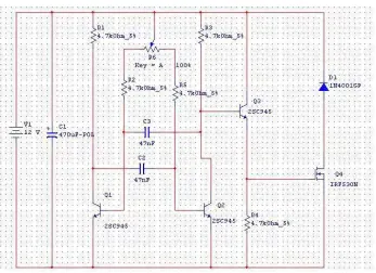
Figure 4.2.1(c): Light dimmer circuit using PWM control method
The PWM circuit requires a steadily running oscillator to operate. The transistors C945 provides an oscillating frequency of 150-450 MHz. Resistors R2 and R5 are used to set the end points of the R6 control, the values shown allow the control to have a full on and a full off setting within the travel of the potentiometer. These part values may be varied to change the behavior of the potentiometer. Q1 is the power switch, it receives the modulated pulse width voltage on the gate terminal and switches the load current on and off through the Source-Drain current path. When Q1 is on, it provides a ground path for the load, when Q1 is off, the load's ground is floating. Diode D1 is a flywheel diode that shorts out the reverse voltage kick from inductive motor loads.
[image:53.612.176.523.66.318.2]Listed below are the components used to construct the circuit. The software used for simulation is Multisim 7. The circuit is then connected to the output device which consists of 12VDC light bulbs. A manual latching pushbutton acts as an on/off switch for the circuit.
Components Label Quantity
470µF electrolytic capacitor C1 1
47nF ceramic disc capacitor C2, C3 2
4.7kΩ resistor R1-R5 5
100kΩ potentiometer R6 1
C945 NPN transistor Q1-Q3 3
IRF530 N-Channel MOSFET Q4 1
IN4001 diode D1 1
12VDC 3W screw type light bulbs 2
Pushbutton (Latching type) 1
4.2.2 Outdoor Lighting
4.2.2.1 Overview
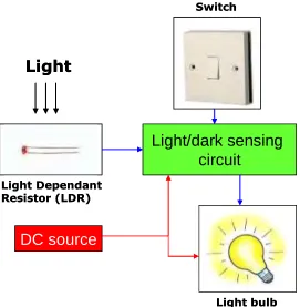
The outdoor lights needs to be turned on and off manually at day and night. To solve this problem, the outdoor lights are connected to a light/dark sensing circuit so that the lights automatically turn on at night and turns off at daytime.
DC source
Light/dark sensing
circuit
Light Dependant Resistor (LDR)
Light bulb Switch
Light
DC source
Light/dark sensing
circuit
Light Dependant Resistor (LDR)
Light bulb Switch
[image:55.612.174.445.75.352.2]Light
Light
Figure 4.2.2(a): Block diagram for Outdoor Lighting
This module is used to illuminate the outdoor areas of the house automatically. This is made possible by using a light/dark sensing circuit. The circuit uses a regular Cadmium-Sulphide Light Dependant Resistor (LDR) which is a variable resistor whose value decreases with increasing incident light intensity. This circuit is used to sense the absence of light and produces an output to energize the relay coils. This will close the contacts and activates the lights where it is connected.
Figure 4.2.2(b): Assembled circuit for the Outdoor Lighting
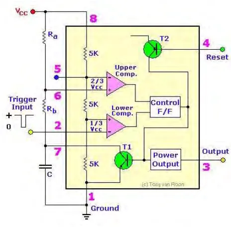
Figure 4.2.2(d): Internal circuit for IC 555 Timer
Pin 1 is connected to ground and Pin 8 is connected to the voltage source of 9V. Pin 2 is the input for lower comparator and is used to set the latch, which in turn causes the output to go high. The LDR and the potentiometer are connected to this pin to provide the ―turn on‖ signal. Pin 3 is the output which turns on the LED and energizes the relay coil. Pin 4 is used to reset the latch and return the output to low state. Pin 5 is the control voltage which provides the reference level for the upper comparator. It is bypassed to ground for noise immunity using a 10nF capacitor. Pin 6 is one input to the upper comparator and is used to reset the latch which causes the output to go low.
In bright light the resistance of the LDR can be as low as 80 ohm and at 50lux (darkness) the resistance increases to over 1 M. The 1M potentiometer control should provide a wide range for light intensities, if not its value may be increased. The timer senses the voltage difference between pins 2 and 6. The control R4 is adjusted so that the relay is off.
4.2.2.4 Hardware and software
Listed below are the components used to construct the circuit. The software used for simulation is Multisim 7. The output from the relay is connected to 9VDC light bulbs. The module can be activated automatically using the LDR sensing or manually using a pushbutton.
A 2-way switch provides selection for auto/manual function. The LED indicates that the circuit is operational and the potentiometer provides calibration for the circuit’s sensitivity according to the LDR’s location.
Components Label Quantity
Timer LM555 1
1MΩ potentiometer R4 1
27kΩ resistor R1 1
510Ω resistor R3 1
10nF ceramic disc capacitor C1 1
Light Emitting Diode LED 1 1
Light Dependant Resistor LDR 1
IN4148 diode D1 1
5V Relay K1 1
9VDC 3W screw type light bulbs 3
Screw type sockets 3
Pushbutton (latching type) 1
4.2.3 Indoor Ventilation
4.2.3.1 Overview
The indoor temperature is high during a hot day causing the resident to feel uncomfortable and sweaty. The warm air is trapped inside the house due to poor indoor ventilation. To solve this problem, an air circulatory system consists of intake & exhaust fans is connected to improve the indoor ventilation. These fans are controlled using temperature sensing circuit.
4.2.3.2 Design
Heat
DC source
Temperature sensing circuit
Thermistor
Switch
Heat Heat
DC source
Temperature sensing circuit
Thermistor Thermistor
Figure 4.2.3(a): Block diagram for Indoor Ventilation
Temperature measurement is the most common application for NTC thermistors. The high sensitivity of thermistors and the ability to manufacture components with tightly controlled temperature accuracy has made the NTC thermistor an ideal device for low cost temperature measurement.
Figure 4.2.3(b): Wheatstone Bridge
sensitivity of the circuit as well as the temperature range for which the circuit is best suited.
The ventilation fans will be activated when the temperature of the house rises above a pre-determined level. For this case we take a nominal room temperature of 27C. When the temperature increases beyond this value, the circuit will activate the relay which activates the ventilation fans located on the above of the house. The ventilation fan purpose is to maintain and lower down the rooms temperature by extracting in the cool air from the outside (intake fan) and discharges the hot air (exhaust fan) from inside the house. When the temperature returns to its nominal value, the ventilation fans stops and returns to its idle state. This value can be changed according to the user preference.
4.2.3.3 Circuit
Figure 4.2.3(d): Temperature sensing circuit for Indoor Ventilation
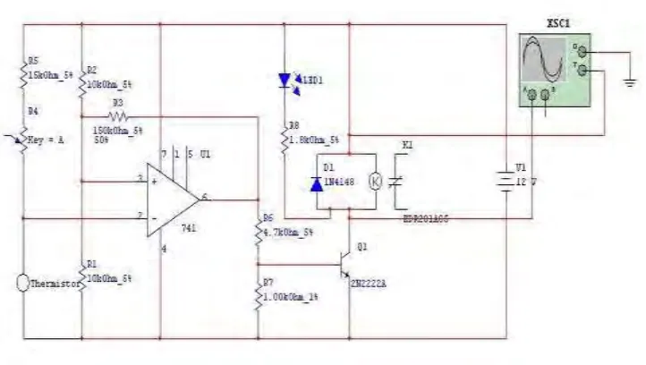
The IC 741 is an operational amplifier used as a differentiator using the values of R1, R2, R5 and the thermistor on both side of the bridge. The 47k thermistor above was rated at 25C with a tolerance of 10%. The thermistor is also known as Negative Temperature Coefficient (NTC) which means that the resistance will decrease when the surrounding temperature increases. R4 is a regular 100kΩ trimmer potentiometer for adjusting over a wide range of temperature. The transistor Q1 acts as the switch for the relay. There will be 2 units of ventilation fans used for the ICTC. One will serve as an intake fan and the other will be the exhaust fan. The fans used are 12VDC rated at 0.13A. The fans will be interconnected to each other via a ventilation shafts which runs through all the rooms in the house. The LED is used to indicate the operation of the circuit. The output of the circuit will be connected to the PLC or an external off-delay timer so that when the circuit is deactivated, the ventilation fans will continue running for 2-3 minutes to make sure that the idle nominal temperature is steadily achieved.
[image:63.612.127.488.74.278.2]Listed below are the components used to construct the circuit. The software used for simulation is Multisim 7. The output of the relay is connected to a 12VDC fan taken from a CPU cooler. The module can be activated automatically using the thermistor sensing or manually using a pushbutton. A 2-way switch provides selection for auto/manual function. The LED indicates that the circuit is operational and the potentiometer provides calibration for the circuit’s sensitivity according to the thermistor’s location. An independent temperature display unit provides the user with the current ambient temperature inside the house.
Figure 4.2.3(f): Temperature display unit
Components Label Quantity
IC 741 Op Amp 741 1
47k@25C thermistor Thermistor 1
15kΩ resistor R5 1
10kΩ resistor R1, R2 2
150kΩ resistor R3 1
4.7kΩ resistor R6 1
1kΩ resistor R7 1
1.8kΩ resistor R8 1
100kΩ potentiometer R4 1
2N2222 transistor Q1 1
5V Relay K1 1
Pushbutton (latching type) 1
2-way selector switch 1
12VDC 0.13A CPU fan 1
Temperature display unit 1
4.2.4 Garbage disposal
4.2.4.1 Overview
The residents sometimes missed the garbage collection time. The garbage spilled when bringing it outside the house and the odor from the garbage attracts flies & brings unwanted disease. To solve this problem, the PLC manages the disposal according to time. A garbage route runs in the underground level of the house and a ventilation system handles the unpleasing odor.
AC Synchronous
Motor
AC Source
Push button
(Manual) Push button (Auto)
DC Source
Proximity sensor
AC Synchronous
Motor
AC Source AC Source
Push button
(Manual) Push button (Auto)
DC Source DC Source
[image:67.612.144.471.443.654.2]Proximity sensor
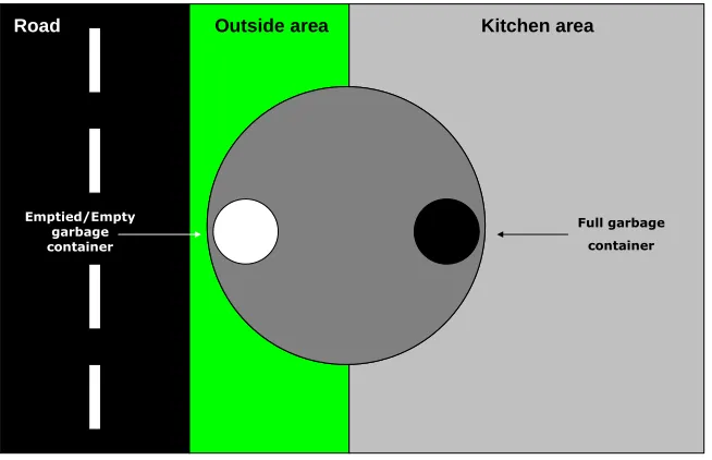
Figure 4.2.4(a): Block diagram for garbage disposal
Full garbage container
Emptied/Empty garbage container
Kitchen area
Road Outside area
To create the rotating platform at the underground level, there are two important parameters that need to be controlled, which is the motor’s speed and direction. The motor speed needs to be maintained at an optimal speed so that the load is not moving to fast or else it will spill on the platform.
The motor moves in a single direction since the platform rotates in a single direction. Even if the motor rotates in the opposite direction (which happened sometimes), there is no problem as long as the 180 degrees rotation is achieved. The motor speed is rated at 5-6 rpm which is suitable enough to provide the rotating functions.
The platform can be rotated automatically or manually according to the situation. The automatic function is achieved using the latching function from the PLC while the manual function is achieved using a manual bypass connection over the PLC relay output. Both functions is activated using pushbuttons.
4.2.4.3 Circuit
There is no circuit used for this module as the module fully utilizes the function of the PLC and the combination of input and output devices.
4.2.4.4 Hardware and software
The output devices for this module include, LEDs used to indicate the platform is in home/idle position and also an AC synchronous motor rated at 6VAC 50/60Hz 1.5/2W 5/6rpm which provides a steady speed and torque rotation for the platform.
The application of PLC makes it possible to reduce the amount of relay used since it has multiple input and output arrangements. The most useful function of the PLC is its latching capability. Listed below are the I/O designations for the PLC.
Input Device Designation
Rotate Command (Auto) Pushbutton I0
Platform Position Proximity Sensor Ib
Output Device Designation
In Position/Ready indicator LED Q0
Rotating indicator LED Q1
Figure 4.2.4(c): Ladder diagram for overall Garbage Disposal module
Figure 4.2.4(d): Inductive proximity sensor used for platform position
Figure 4.2.4(e): AC Synchronous motor used for platform rotation
Listed below are the components used to construct the circuit. The software used for simulation is Zen Support Software. This software is used by creating ladder diagrams before programmed into the PLC unit via a communication cable.
Components Quantity
Omron Zen PLC 1
Push buttons 2
Inductive proximity sensor 1
LED 2
6VAC synchronous motor 1
4.2.5 Garage and car park
4.2.5.1 Overview
Residents accidentally hit the wall or children while reversing the vehicle and sometimes forget to close the garage door after they left the house. To solve this problem, the car park will automatically rotate the vehicle facing the front and the garage doors will close automatically after a while.
4.2.5.2 Design
Garage
Rotating
parking
Garage
Figure 4.2.5(a): Concept diagram for garage and car park
PLC AC Synchronous motor Optical distance
sensor switchesLimit
DC source
Garage Door
(Open/Close) AC source
Remote Control (Garage Door
& Platform)
PLC AC Synchronous motor Optical distance
sensor switchesLimit
DC source
Garage Door
(Open/Close) AC source
Remote Control (Garage Door
& Platform)
Figure 4.2.5(b): Block diagram for garage and car park
The garage/car park system is identical to the garbage disposal system. There are also two important parameters that need to be controlled, which is the motor’s speed and direction. The motor speed needs to be reduced to an optimal speed so that the car is rotated at a suitable safe speed. A high speed would cause the car to fall of from the platform.
Figure 4.2.5(c): Limit switch and triangular marker
The garage and car park system operates using many sensors and switches. The optical distance sensor is used to detect when the car is in position to enter the garage. The garage door opens and actuates the maximum door limit switch which activates a 10 second timer. Within the allocated time, the vehicle must enter the garage and the garage door automatically closes.
When the vehicle wishes to leave the garage, the user can open the garage door manually (by pressing the open door pushbutton) or by pressing the ―unlock‖ button on the remote control.
4.2.5.3 Circuit
There is no circuit used for this module as the module fully utilizes the function of the PLC and the combination of input and output devices.
4.2.5.4 Hardware and software
Figure 4.2.5(e): Optical distance sensor
The output devices for this module include, LEDs used to indicate the platform is in home/idle position or rotating, an AC synchronous motor rated at 6VAC 50/60Hz 1.5/2W 5/6rpm which provides a steady speed and torque rotation for the platform and also 12VDC light bulbs to indicate the garage door coil is open or close.
Input Device Designation
Rotate command (Auto) Pushbutton I1
Reset/Stop rotate Pushbutton I2
Maximum door position Limit switch I4
Minimum door position Limit switch I5
Rotate command (Remote) Remote I6
Platform position Limit switch I7
Open door command Pushbutton/Remote I8
Close door command Pushbutton/Remote I9
Close door command (Delayed) Optical distance sensor Ia
Output Device Designation
In Position/Ready indicator LED Q2
Rotating indicator LED Q3
Rotating platform motor Synchronous motor Q5
Open garage door coil 12VDC light bulb Q6
Figure 4.2.5(g): Ladder diagram for rotating platform
Listed below are the components used to construct the circuit. The software used for simulation is Zen Support Software. This software is used by creating ladder diagrams before programmed into the PLC unit via a communication cable.
Components Quantity
Omron Zen PLC 1
Push buttons 5
Optical distance sensor 1
LED 2
6VAC synchronous motor 1
6VAC adapter 1
Limit switches 3
Light bulbs socket 2
4.2.6 Events alert
4.2.6.1 Overview
Normal house does not have fire and flood detection system to alert the occupants of danger and disaster. To fix this problem, a heat & smoke sensor is added for fire detection and a water level sensor is added for flood detection.
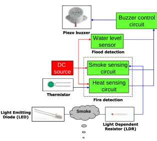
[image:80.612.152.466.330.613.2]4.2.6.2 Design Smoke Buzzer control circuit Smoke sensing circuit Heat sensing circuit Water level sensor Fire detection DC source Flood detection Thermistor Light Dependent Resistor (LDR) Light Emitting Diode (LED) Piezo buzzer Smoke Buzzer control circuit Smoke sensing circuit Heat sensing circuit Water level sensor Fire detection DC source Flood detection Thermistor Thermistor Light Dependent Resistor (LDR) Light Emitting Diode (LED) Piezo buzzer
Figure 4.2.6(a): Block diagram for Events Alert
system. The heat circuit is similar as the ones used for the indoor ventilation module. The difference lies in its activation threshold which detects a higher temperature before it activates the buzzer circuit. The smoke sensor detects smoke produced from the fire.
The water level sensor acts as the flood detector which monitors water level in drainage. The buzzer control circuit is used to vary the interval between beeps as user’s reference.
4.2.6.3 Circuit
4.2.6.3.1 Water Level Sensor
Figure 4.2.6(c): Water Level Sensor circuit for Events Alert
[image:82.612.148.465.68.262.2]4.2.6.3.2 Heat Sensing
Figure 4.2.6(d): Assembled circuit for Heat Sensing
The IC 741 is an operational amplifier used as a differentiator using the values of R1, R2, R5 and the thermistor on both side of the bridge.The 47k thermistor above was rated at 33C with a tolerance of 10%. The thermistor is also known as Negative Temperature Coefficient (NTC) which means that the resistance will decrease when the surrounding temperature increases. R4 is a regular 1MΩ trimmer potentiometer for adjusting over a wide range of temperature. The transistor Q1 acts as the switch for the relay. The LED is used to indicate the operation of the circuit. The output of the circuit is connected to the buzzer interval circuit and the buzzer will sound when a heat from fire is detected.
4.2.6.3.3 Smoke Sensor
[image:84.612.170.443.404.608.2]
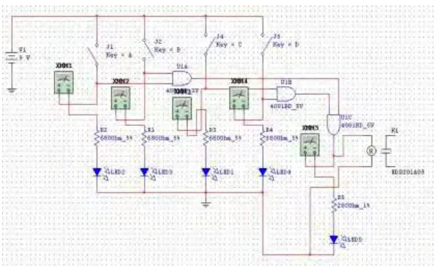
Figure 4.2.6(g): Smoke Sensor circuit for Events Alert
4.2.6.3.4 Buzzer Interval
[image:86.612.145.465.479.674.2]
Figure 4.2.6(h): Assembled circuit for Buzzer Interval
Figure 4.2.6(i): Buzzer Interval circuit for Events Alert
While J1 remains open, the circuit uses virtually no current. When the switch is closed, the buzzer produces a series of beeps at a certain intervals. R3 & C2 sets the length of beeps while R4 & C2 sets the delay between the beeps. If the initial values are doubled, then the interval would double as well. Gates 5 & 6 of the CMOS 4011 is not used in the circuit. When the oscillator is running, pin 10 keeps switching back and forth between high to low. Pin 11 supplies base current to Q1 - through R4. As pin 10 switches on and off - the transistor switches on and off. While the transistor is on - it connects the negative lead of the Buzzer to ground - and the Buzzer sounds. To keep the standby current low - the value of 4.7MΩ was chosen for R1 and the current through R1 is flowing to ground through the switch. This means that Pin 1 & 2 is low - and C1 is discharged. And while pin 10 remains low, the Buzzer is silent.
4.2.6.4 Hardware and software
Listed below are the components used to construct the circuit. The software used for simulation is Multisim 7.
Water Level Sensor
Components Label Quantity
CMOS 4081 Quad AND gates 4081 1
680Ω resistor R1-R4 4
280Ω resistor R5 1
Light Emitting Diode LED1-5 5
Heat Sensing
Components Label Quantity
IC 741 Op Amp 741 1
33k@25C thermistor Thermistor 1
15kΩ resistor R5 1
10kΩ resistor R1, R2 2
150kΩ resistor R3 1
4.7kΩ resistor R6 1
1kΩ resistor R7 1
1.8kΩ resistor R8 1
100kΩ potentiometer R4 1
2N2222 transistor Q1 1
Light Emitting diode LED 1 1
IN4148 diode D1 1
5V Relay K1 1
Smoke Sensor
Components Label Quantity
555 Timer LM555 1
1MΩ potentiometer R4 1
27kΩ resistor R1 1
510Ω resistor R2, R3 2
Light Emitting Diode LED 1, 2 2
Light Dependant Resistor LDR 1
IN4148 diode D1 1
5V Relay K1 1
Buzzer Interval
Components Label Quantity
CMOS 4011 Quad NAND gates 4011 1
680nF ceramic disc capacitor C2 1
100nF ceramic disc capacitor C1, C3 2
4.7MΩ resistor R1, R2 2
470kΩ resistor R3 1
4.7kΩ resistor R4 1
IN4148 diode D1, D2 2