UNIVERSITI TEKNIKAL MALAYSIA MELAKA
STUDY ON TOOL WEAR EFFECT ON MACHINING DIFFERENT
TYPE OF MATERIALS
This report submitted in accordance with requirement of the Universiti Teknikal
Malaysia Melaka (UTeM) for the Bachelor Degree of Manufacturing Engineering
(Manufacturing Process) with Honours.
by
SYARIFAH BALQIS BINTI SYED MOHAMED
FACULTY OF MANUFACTURING ENGINEERING
DECLARATION
I hereby, declared this report entitled “Study on Tool Wear Effect on Machining
Different Type of Materials” is the results of my own research except as cited in
references.
Signature : ………...
Author’s Name :…SYARIFAH BALQIS BINTI SYED MOHAMED…
APPROVAL
This report is submitted to the Faculty of Manufacturing Engineering of UTeM as a
partial fulfillment of the requirements for the degree of Bachelor of Manufacturing
Engineering (Manufacturing Process) with Honours. The member of the supervisory
committee is as follow:
(Signature of Supervisor)
………...
I
DECLARATION
I hereby, declare that this report entitled “STUDY ON TOOL WEAR EFFECT
ON MACHINING DIFFERENT TYPE OF MATERIAL” is the result of my own
research except as cited in the references.
Signature :
Author‟s Name : Syarifah Balqis Binti Syed Mohamed
II
APPROVAL
This report is submitted to the Faculty of Manufacturing Engineering of UTeM as a
partial fulfillment of the requirements for the degree of Bachelor of Manufacturing
Engineering (Manufacturing Process) with Honours. The members of the supervisory
committee are as follow:
……….
DR. MOHD RIZAL BIN SALLEH
III
ABSTRACT
This paperwork contains the report of the tool wear effect when machining different
materials by using coated carbide tool. The materials used are mild steel and stainless
steel. This The aim of this paperwork is to present the flank wear that occurred when
machining mild steel and stainless steel using coated carbide tool with different
parameter setting. Machining performance is determined by referring to flank wear
obtained from the experiment. The machinery used in this experiment is
conventional lathe machine. The material used for mild steel is mild steel with
diameter 25 mm and for stainless steel is stainless steel with diameter 20 mm. The
parameters varied are depth of cut, cutting speed and feed rate. The depth of cut is set
to be 0.5 mm and 1.5 mm, with cutting speed 85 m/min. and 115 m/min, and feed
rate 0.15 mm/rev. and 0.35 mm/rev. These variable are arranged according to the full
factorial design. Wear that appeared on the cutting tool is measured with Sereo Zoom
Microscope (SZM) and analyzed with Minitab software. From the result obtained,
cutting speed and feed rate are the most significant factor that effect tool wear of the
IV
ABSTRAK
Kertas kerja ini mengandungi laporan mengenai kajian kehausan mata alat pemotong
apabila proses pemotongan dilakukan ke atas bahan yang berbaeza dengan
menggunakan mata alat karbida yang disadur. Bahan yang digunakan adalah mild
steel dan stainless steel. Kertas kerja ini adalah bertujuan untuk menunjukkan „flank wear‟ yang terhasil apabila memotong dengan menggunakan factor yang berbeza. Tahap proses pemotongan dikaji berdasarkan „tool wear‟ yang terhasil daripada
eksperimen. Mesin yang digunakan untuk eksperimen ini adalah mesin larik.
Diameter bahan yang digunakan masing2 adalah 25 mm untuk „mild steel‟ dan 20 mm untuk „stainless steel‟. Fktor-faktor yang berubah ialah kedalaman pemotongan,
kelajuan pemotongan, dan kadar pemotongan.kedalaman pemotongan yang
digunakan ialah 0.5mm dan 1.5 mm manakala kelajuan pula ialah 85 m/min dan 115
m/min dengan kadar pemotongn sebanyak 0.15 mm/rev dan 0.35 mm/rev.
Faktor-faktor ini disusun di dalam jadual mengikut „full factorial design‟. Kehausan yang
terhasil pada mata alat diukur dengan menggunakan „Stereo Zoom Microscope‟dan
dianalisis menggunakan Minitab Software. Daripada keputusan yang diperolehi,
kelajuan dan kadar emotongan merupakan factor yang paling mempengaruhi
V
DEDICATION
VI
ACKNOWLEDGEMENT
First of all, I am grateful to Allah for giving me the chance to complete this project
of “Study on Tool Wear Effect on Machining Different Type of Material” I also want
to thank to Allah for giving me physically and mentally strength during the project
progress. I would like to thank the most person that is behind this project, my
supervisor, Dr. Mohd Rizal Bin Salleh, who always behind me until this project is
completed. He supports me and gave me advice during the time to finish the study
and complete the paper work. Then, I would like to thank the entire technician from
FKP for helping me especially during the lab session. Not forgotten my beloved
family and friends that always support me and be behind me. Finally, I would like to
VII
TABLE OF CONTENT
Declaration I
Approval II
Abstract III
Abstrak IV
Dedication V
Acknowledgement VI
Table of content VII
List of tables X
List of figures XI
List of abbreviations XIII
1. INTRODUCTION 1
1.1 Background 1
1.2 Problem statement 4
1.3 Objectives 4
VIII
2. LITERATURE REVIEW 6
2.1 Cutting process 6
2.2 Machining parameter 10
2.2.1 Speed 10
2.2.2 Feed 10
2.2.3 Depth of cut 11
2.2.4 Temperature 11
2.3 Tool wear 12
2.3.1 Tool wear phenomenon 14
2.3.1.1Flank wear 14
2.3.1.2Crater wear 14
2.3.1.3Notch wear 15
2.3.1.4Plastic deformation of tool tip 15
2.3.1.5Chipping 15
2.4 Cutting tool material 15
2.4.1 High speed steel toolbits 16
2.4.2 Cast alloy toolbits 17
2.4.3 Cemented-carbide toolbits 17
2.4.4 Coated carbide toolbits 18
2.4.5 Ceramic toolbits 18
2.4.6 Cermet toolbits 19
2.4.7 Diamond toolbits 19
2.4.8 Cubic boron nitride toolbits 19
2.5 Cutting tool material selection 20
2.6 Coating 21
2.6.1 Material used in coating 22
2.6.1.1Common tool coated material 23
2.6.1.2New coated material 24
2.7 Materials 27
3. METHODOLOGY 28
3.1 Introduction 28
IX
3.2.1 Lathe component 29
3.2.2 Stereo zooming microscope 30
3.2.3 Cutting parameter 31
3.3 Cutting tool selection 32
3.3.1 Tool holder 32
3.4 Work material selection 33
3.4.1 Stainless steel 33
3.4.2 Mild steel 34
3.5 Design of experiment 35
3.5.1 Full Factorial Design 36
3.6 Experimental procedure 38
4. RESULT AND ANALYSIS 41
4.1 tool wear effect on machining different type of materials by
conventional machining 41
4.2 Data analysis 44
5. DISCUSSION 57
5.1 Discussion for the experiment 57
6. CONCLUSION AND RECOMMENDATION 64
6.1 Conclusion 64
6.2 Recommendation 65
REFERENCES 66
APPENDICES
A Machine specification for lathe
X
LIST OF TABLES
2.1 Values of a and b for Carbide and High Speed Steel Tool
Material
12
3.1 General recommendation for turning operation using coated
carbide tool
31
3.2 Mechanical Properties of stainless steel 304 33
3.3 Physical Properties of stainless steel 304 34
3.4 Mechanical Properties of mild steel 34
3.5 Physical Properties of mild steel 35
3.6 Control factor for machining mild steel and stainless steel 37
3.7 Orthogonal array for machiningmild steel and stainless steel 37
4.1 Machining parameters 41
4.2 Result of flank wear 42
4.3 Estimated Effects for average flank wear. 44
4.4 Data means for main effects plot for independent variables 47
4.5 Data means for main effects plot for interaction between variables 49
4.6 Data means for main effects plot for interaction between DOC,
material and FR
53
4.7 Data means for main effects plot for interaction between DOC,
material and CS
53
4.8 Data means for main effects plot for interaction between DOC,
FR and CS
54
4.9 Data means for main effects plot for interaction between material,
FR and CS
54
4.10 Data means for main effects plot for interaction between DOC, material, FR, CS
XI
LIST OF FIGURES
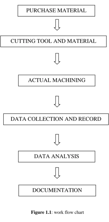
1.1 Work Flow Chart 6
2.1 Turning Process 8
2.2 Cutting-off Process 8
2.3 Face Milling 9
2.4 End Milling 9
2.5 Illustration of Speed, Feed and Depth Of Cut 11
2.6 Tool wear (a) Flank wear (b) Crater Wear (c) Notch wear (d)
Nose radius wear
13
2.7 Illustration of Crater Wear and Flank Wear 14
3.1 Lathe Machine (brand name: Momax) 29
3.2 Stereo Zoom Microscope 31
3.3 Coated Carbide Insert 32
3.4 Tool Holder for coated carbide tool 33
3.5 Flow Chart to Investigate the Tool Wear Effect on Machining
Different Type of Materials by Conventional Machining
39
4.1 flank wear is 0.36 when turning stainless steel at cutting speed
115 m/min, depth of cut 1.5mm and feed rate 0.35 mm/rev.
43
4.2 flank wear is 0.32 when turning stainless steel at cutting speed
85m/min, depth of cut 1.5mm and feed rate 0.35 mm/rev.
43
4.3 Normal Probability Plot of the Effects for average Vb 45
4.4 Pareto Chart of the Effects for average Vb 46
XII
4.6 Interaction plot (data means) for average Vb 48
5.1 flank wear is 0.36 when turning stainless steel at cutting speed
115 m/min, depth of cut 1.5mm and feed rate 0.35 mm/rev.
58
5.2 flank wear is 0.30 when turning stainless steel at cutting speed 85
m/min, depth of cut 0.5mm and feed rate 0.15 mm/rev.
58
5.3 flank wear is 0.32 when turning stainless steel at cutting speed
85m/min, depth of cut 1.5mm and feed rate 0.35 mm/rev.
59
5.4 flank wear is 0.32 when turning stainless steel at cutting speed
115m/min, depth of cut 0.5 mm and feed rate 0.15 mm/rev.
59
5.5 flank wear is 0.34 when turning stainless steel at cutting speed
115m/min, depth of cut 0.5 mm and feed rate 0.35 mm/rev.
60
5.6 flank wear is 0.35 when turning mild steel at cutting speed
115m/min, depth of cut 1.5 mm and feed rate 0.35 mm/rev.
60
5.7 flank wear is 0.34 when turning mild steel at cutting speed
115m/min, depth of cut 0.5 mm and feed rate 0.35 mm/rev.
61
5.8 flank wear is 0.32 when turning mild steel at cutting speed
85m/min, depth of cut 0.5 mm and feed rate 0.35 mm/rev
61
5.9 flank wear is 0.33 when turning stainless steel at cutting speed
85m/min, depth of cut 0.5 mm and feed rate 0.35 mm/rev.
XIII
LIST OF ABBREVIATIONS
Al2O3 – Aluminium Oxide
CNC –- Computer Numerical Control
CrC – Chromium Carbide
CS – Cutting speed
CVD – Chemical Vapour Deposition
DOC – Depth of Cut
DOE – Design of Experiment
f – feed
FR – Feed rate
HSS – High Speed Steel
OA – Orthogonal Array
PCBN – Polycrystalline Cubic Boron Nitride
PCD – Polycrystalline Diamond
Rpm – revolution per minute
Sfpm – surface feed per minute
XIV
TiAlN – Titanium Aluminium Nitride
TiC – Titanium Carbide
TiCN – Titanium Carbonitride
TiN – Titanium Nitride
V – cutting speed
Vb – Flank wear
1
CHAPTER 1
INTRODUCTION
1.1 BACKGROUND
Machining performance of tool coating is subjected to investigate the capabilities and
limitations of coating material to different substrate (base material of cutting tool) in
machining. To achieve the machining performance of tool coating, the tool’s material
must possess high strength at elevated temperature, good oxidation resistant, low
coefficient of thermal, resistant to wear, chemical reactance resistance and high
conductivity and can withstand for a long time for machining (Kalpakjian and
Schmid, 2001). The conventional process cycle in the fabrication of hardened steel
parts consists of initial turning, followed by hardening treatment and, finally, by
finish grinding to obtain the desired dimensional accuracy and surface finish. Such
an approach is characterised by drawbacks in terms of long time required by the
finishing operation and number of operations involved. Furthermore, the potential for
thermal damage in grinding is higher than in cutting operations with geometrically
defined tools, with the formation of a thicker hard white layer (Bruni et al., 2007).
The alternative approach, consisting of turning the workpiece to its final dimension
in the hardened state, can allow to reduce the white layer thickness, save time,
decrease the number of operations of the process route, and manufacture complex
geometries in one setup. This produces, in most cases, a substantial reduction of the
manufacturing costs and makes such process very attractive in the manufacturing of
2
Turning is a form of machining, a material removal process, which is used to create
rotational parts by cutting away unwanted material. The turning process requires a
turning machine or lathe machine, workpiece, fixture, and cutting tool. The
workpiece is a piece of pre-shaped material that is secured to the fixture, which itself
is attached to the turning machine, and allowed to rotate at high speeds. The cutter is
typically a single-point cutting tool that is also secured in the machine, although
some operations make use of multi-point tools. The cutting tool feeds into the
rotating workpiece and cuts away material in the form of small chips to create the
desired shape.
Turning is used to produce rotational, typically symmetric axis, parts that have many
features, such as holes, grooves, threads, tapers, various diameter steps, and even
contoured surfaces. Parts that are fabricated completely through turning often include
components that are used in limited quantities, perhaps for prototypes, such as
custom designed shafts and fasteners. Turning is also commonly used as a secondary
process to add or refine features on parts that were manufactured using a different
process. Due to the high tolerances and surface finishes that turning can offer, it is
ideal for adding precision rotational features to a part whose basic shape has already
been formed.
Turning machines, typically referred to lathes, can be found in a variety of sizes and
designs. While most lathes are horizontal turning machines, vertical machines are
sometimes used for large diameter workpieces. Turning machines can also be
classified by the type of control that is offered. A manual lathe requires the operator
to control the motion of the cutting tool during the turning operation. Turning
machines are also able to be computer controlled, in which case they are referred to
as a computer numerical control (CNC) lathe. CNC lathes rotate the workpiece and
move the cutting tool based on commands that are preprogrammed and offer very
high precision. In this variety of turning machines, the main components that enable
the workpiece to be rotated and the cutting tool to be fed into the workpiece remain
the same.
The tooling that is required for turning is typically a sharp single-point cutting tool
3
insert attached to the end. These inserts can vary in size and shape, but are typically a
square, triangle, or diamond shaped piece. These cutting tools are inserted into the
turret or a tool holder and fed into the rotating workpiece to cut away material. These
single point cutting tools are available in a variety of shapes that allow for the
formation of different features. All cutting tools that are used in turning can be found
in a variety of materials, which will determine the tool's properties and the workpiece
materials for which it is best suited. These properties include the tool's hardness,
toughness, and resistance to wear. The most common tool materials that are used
include,high-speed steel (HSS), carbide, carbon steel and cobalt high speed steel. The
material of the tool is chosen based upon a number of factors, including the material
of the workpiece, cost, and tool life.
In turning, the raw form of the material is a piece of stock from which the
workpieces are cut. This stock is available in a variety of shapes such as solid
cylindrical bars and hollow tubes. Turning can be performed on a variety of
materials, including most metals and plastics. Common materials that are used in
turning include aluminum, brass, magnesium, nickel, steel, thermoset plastics,
titanium and zinc. When selecting a material, several factors must be considered,
including the cost, strength, resistance to wear, and machinability. The machinability
of a material is difficult to quantify, but can be said to posses the characteristics such
as results in a good surface finish, promotes long tool life, requires low force and
power to turn and provides easy collection of chips.
Most defects in turning are inaccuracies in a feature's dimensions or surface
roughness. There are several possible causes for these defects, including incorrect
4
1.2 PROBLEM STATEMENTS
The coating of carbide cutting tools with thin surfaces layers of materials such as
titanium carbide (TiC) has now been carried out for many years in order to improve
their machining performance. The use of coating materials to enhance the
performance of cutting tool is not a new concept. The first coated cemented carbide
indexable inserts for turning were introduced in 1969 and had an immediate impact
on metal cutting industry. These first generation TiC coated carbide tools were
initially used in interrupted cutting applications such as the milling of steels.
However, over the last few years there has been a considerable amount of interest in
a new generation of coatings with significantly improved performance compared to
conventional coatings. Today, 70% of cemented carbide tools used in the industry is
coated. However, the tool wear still occur on the coated cutting tool. There are now
efforts to produce the cutting tool locally thorough knowledge of the cutting process
so that requirements of the tools are correctly identified.
1.3 OBJECTIVES
The objectives of this study is to focus on:-
Investigation on tool wear effect of machining different materials. To study about the tool wear progression on the cutting tools used.
5
1.4 SCOPE OF STUDY
Coated carbide tools have found widespread use in today’s metal cutting industry,
bringing about significant improvements in tool performance and cutting economy
through lower the tool wear. For this project, the work will involve the setting-up and
running of machining trial using coated carbide tool followed by detailed
examination of the used tools and work materials using Stereo Zoom Microscopes.
Work materials uses are mild steel and stainless steel. The tool wear will be obtain
during machining trial is examine and analyze their result to relate with capabilities
and limitations of tool coating (TiC) when applied to cutting tools. From that, the
machining performance of the machining process that related with tool coating
(cutting tool) will be find out. The results obtained will be extremely important in helping to develop the next generation of cutting tool coatings by quantifying their
performance using series of controlled and scientific tests. There is also the intention
6
To further this investigation, here are the process flow of the experiment.
PURCHASE MATERIAL
DATA COLLECTION AND RECORD CUTTING TOOL AND MATERIAL
SELECTION
DOCUMENTATION ACTUAL MACHINING
PROCESS
[image:24.595.200.431.120.591.2]DATA ANALYSIS