UNIVERSITI TEKNIKAL MALAYSIA MELAKA
DEVELOPMENT OF AC POWER CONTROL USING
SMARTPHONE VIA BLUETOOTH
This report submitted in accordance with requirement of the Universiti Teknikal
Malaysia Melaka(UTeM) for the Bachelor Degree of Electronics Engineering
Technology (Industrial Electronics) (Hons.)
By
LIEW FU HUA B071310522 930830-14-5323
FACULTY OF ENGINEERING TECHNOLOGY
DEVELOPMENT OF AC POWER CONTROL USING
SMARTPHONE VIA BLUETOOTH
LIEW FU HUA
B071310522
UNIVERSITI TEKNILKAL MALAYSIA MELAKA
DECLARATION
I hereby, declared this report entitled “Development of AC Power
Control Using Smartphone Via Bluetooth” is the results of my
own research except as cited in reference.
Signature
:
……….
Author’s Name
:
……….
APPROVAL
This report is submitted to the Faculty of Engineering Technology of UTeM as a partial
fulfillment of the requirements for the degree of Bachelor Degree of Electronics
Engineering Technology (Industrial Electronics) (Hons.). The member of the
supervisory is as follow:
i
ABSTRACT
Nowadays, AC power control has becoming a common issue relates to the energy
efficiency. The drop in efficiency mostly because of electrical energy consumed by the
electrical devices. AC power control can be controlled by adjusting the desired level of
output power of the electrical device. The present technology is able to feedback the
ambient light intensity to adjust the require output power deliver to the light by using
sensors. Although the present technology is mostly designed with self-controlled system,
but are these devices really can give the desired output power to achieve the higher
efficiency. Hence, the solution to solve this issue is to control the electrical appliances
with Bluetooth signal. The electrical appliance is control manually by using Bluetooth
device. Furthermore, disabilities they need this device to control the desired output power.
The development of AC power control using smartphone via Bluetooth is designed with
the microcontroller to adjust the servo motor and the motor is attached to the potentiometer
which can adjust the output voltage deviate from 240V to the load. The servo motor as the
mechanical way to control the potentiometer is because the motor and the electronics
components could not withstand as much 240V from the source. Therefore, the output
voltage to the load is able to control at voltage range of 0V - 240V. The servo motor will
only rotate when the Bluetooth signal from smartphone is sent to the Bluetooth device
which connected to the PIC microcontroller. The software for the smartphone to control
ii
ABSTRAK
Kini, kawalan kuasa AC telah menjadikan isu biasa yang berkaitan dengan
kecekapan tenaga. Kejatuhan dalam kecekapan kebanyakan disebabkan oleh tenaga
elektrikal yang digunakan dalam alatan elektrikal. Kawalan kuasa AC boleh dikawalkan
dengan melaraskan kuasa keluaran alatan elektikal pada tahap kemahuan. Teknologi
terkini adalah memboleh intensiti cahaya ambien sebagai maklum balas untuk melaraskan
kuasa keluaran yang dikehendaki dan digunakan sebagai tenaga cahaya dengan
menggunakan sensor. Walaupun teknologi terkini kebanyakan dicipta dengan sistem
ubahsuai sendiri, tetapi sejauh manakah alatan ini betul boleh memberikan kuasa keluaran
yang dimahukan untuk mencapai kecekapan yang lebih optimum. Jadi, solusi untuk
menangani masalah ini adalah mengawal alatan elektrikal dengan menggunakan isyarat
Bluetooth. Alatan elektrikal adalah dikawal secara manual dengan applikasi Bluetooth.
Di samping itu, orang kurang upaya perlukan alat ini untuk mengawal kuasa keluaran
yang dimahukan kepada mereka. ‘Pembangunan kawalan kuasa AC mengguna telefon pintar melalui Bluetooth’ adalah dicipta dengan mikro-pengawal untuk melaras motor
servo dan motor itu adalah digabungkan dengan potentiometer dimana ia boleh melaras
voltan keluaran simpang dari 240V kepada beban. Motor servo sebagai cara mekanikal
untuk mengawal potentiometer adalah disebabkan motor dan komponen elektronik tidak
boleh tahan voltan 240V. Oleh itu, motor akan pusing bila isyarat Bluetooth dari telefon
pintar kepada alat Bluetooth dimana telah disambung dengan mikro-pengawal. Perisian
untuk dikawal dalam telefon pintar adalah dicipta dengan MIT Apps Inventor (asas Adroid
iii
DEDICATION
To my beloved parents this thesis is dedicated to them,
iv
ACKNOWLEDGEMENT
First and foremost, I have to thank my parents for their love and support
throughout my life. Thank you both for giving me strength to reach for the stars and chase
my dreams. My sisters, aunties and cousins deserve my wholehearted thanks as well. I
would like to sincerely thank my supervisor, Encik Wan Norhisyam Bin Rashid, for his
guidance and support throughout this study, and especially for his confidence in me.
Furthermore, I would also like to thank him for serving as a member on my thesis
committee and approve my FYP title. His comments and questions were very beneficial
in my completion of the manuscript and especially at interview time. I learned from his
insight a lot. I was grateful for the discussion and interpretation of some results presented
in this thesis.
To all my friends, thank you for your understanding and encouragement in my
many moments of crisis. Your friendship makes my life a wonderful experience. I cannot
list all the names here, but you are always on my mind.
Thank you, Lord, for always being there for me. This thesis is only a beginning
v
TABLE OF CONTENT
Abstract i
Dedication iii
Acknowledgement iv
Table of Content v
List of Tables vii
List of Figures viii
CHAPTER 1: INTRODUCTION 1
1.1 Background 2
1.2 Problem Statement 4
1.3 Objectives 4
1.4 Scopes 4
1.4 Thesis Organization 5
CHAPTER 2: LITERATURE REVIEW 6
2.1 Introduction of Literature Review 7
2.2 Demonstration of others Power Control Design 8 2.2.1 Method 1 - Intelligent Light Control System 8 2.2.2 Method 2 - Remote Controllable Power Outlet 10
2.2.3 Method 3 – Power Remote Monitoring and Control 12 2.2.4 Method 4 – Automatic Room Light Intensity Detection 15 2.2.5 Method 5 – Home Appliance Control System on Android 17
vi
CHAPTER 3: METHODOLOGY 21
3.1 Methodology 22
3.2 Expected Result 22
3.3 Backgrounds 23
3.3.1 Bluetooth 23
3.3.2 PIC Microcontroller 24
3.3.3 Software Development Tool on PIC 24
3.3.4 Programming PIC Microcontroller 26
3.3.5 Bluetooth Programming Concept 27
3.3.6 Servo Motor 28
3.3.7 MIT App Inventor 29
3.4 Related Theory 30
3.5 Circuit Design 31
3.6 System Flowchart 34
CHAPTER 4: RESULTS AND DISCUSSION 38
4.1 Introduction 39
4.2 Discussion 39
4.3 Analysis Results 45
4.3.1 Tested Outcome 45
4.3.2 Product Market Demand Test 48
CHAPTER 5: CONCLUSION AND RECOMMENDATION 61
5.1 Introduction 62
5.2 Conclusion 62
5.3 Recommendation 63
vii
LIST OF TABLE
2.2.1: Summary of Author, Design Title and their Description 19
2.3.1: Comparison of other Method with my Design 20
3.3.4: Pin Selectors for 40-Pin PCI Microcontroller Devices 27
3.6.1: The relationship between the servo motor angle and output AC voltage 37
4.3.1.1: Results for Wind Speed Test of Fan 47
4.3.2.1: Response for Question 1 49
4.3.2.2: Response for Question 2 52
4.3.2.3: Response for Question 3 55
4.3.2.4: Response for Question 4 57
viii
LIST OF FIGURES
2.1.1: Expected circuit for AC Power Control Using Smartphone Via Bluetooth 7
2.2.1.1: System Components and physical connectivity 8
2.2.1.2: System Control Loop 9
2.2.2.1: Remote-Controllable power outlet system 10
2.2.2.2: The complete block of the WPCOM 11
2.2.3.1: Wireless power remote controller architecture 12
2.2.3.2: Functional block diagram of central control module 13
2.2.4.1: Room light intensity detection and control architecture 15
2.2.4.2: The circuit diagram of the HLCM 15
2.2.5.1: System Architecture 17
2.2.5.2: Wireless switch structure 17
3.3.3: Create Project Wizard in MPLAB IDE 25
3.3.6: Servomotor 28
3.3.7: MIT App Inventor 29
3.4.1: Circular rheostat and Potentiometer 30
3.5.1: 5V DC supply from AC transformer and Rectifier 31
3.5.2: The Main circuit of PIC and Bluetooth 31
3.5.3: Clock Circuit 32
3.5.4: Servo Motor and the Controlled Output Voltage 32
3.6.1: System Flowchart of Bluetooth Control Device 34
ix 4.2.1: Front Panel of MIT Apps Inventor 39
4.2.2: Block Diagram (1) 40
4.2.3: Block Diagram (2) 40
4.2.4: Code of the PIC 42
4.2.5: K150 Programmer 43
4.2.6: Microbrn.exe layout 44
4.3.1.1: Hardware testing using Windspeed detection 45
4.3.1.2: Smartphone GUI when Bluetooth is Not Connected, and Connected 46
4.3.1.3: Bluetooth Devices ready to pair, HC-05 46
4.3.2.1: Respondents Gender Ratio 48
4.3.2.2: Respondents Age Group Ratio 48
4.3.2.3: Bar Chart for Question 1 49
4.3.2.4: People who answered positive answer for Question 1 50
4.3.2.5: People who answered negative answer for Question 1 50
4.3.2.6: Bar Chart for Question 2 52
4.3.2.7: People who answered positive answer for Question 2 53
4.3.2.8: People who answered negative answer for Question 2 53
4.3.2.9: Bar Chart for Question 3 55
4.3.2.10: People who answered positive answer for Question 3 56
4.3.2.11: Bar Chart for Question 4 57
4.3.2.12: Bar Chart for Question 5 58
4.3.2.13: People who answered positive answer for Question 5 59
1
2
1.1
BackgroundThe AC power control is technology to use device to control the output voltage
delivers to the load to achieve higher efficiency. In this technology, we can control the
desired output power more precisely other than using the old-school discrete control (e.g
ceiling fan). The power control is able to control the output from 0% - 100% and precision
is up to sensitivity of 1%.
Ying-Wen Bai and Yi-Te Ku (2008) have described in recent years the energy crisis
has become one problem which the whole world must face. The home power
consumptions are the largest part of energy consumption in the world. In particular, the
electricity consumption of lamps in a typical domestic house is a factor which can’t be
neglected. The desired light intensity of differ to many place due to its ambient.
Sometimes it is sufficient light source from outside, and thus light does not necessary to
be always on. Also, some users are not turn off the light if it is not necessary. These could
be the major problem on energy wasting. Therefore, an advance power management of
light control in a home is launched in order to save energy.
Chia-Hung Lien, Ying-Wen Bai, and Ming-Bo Lin, Member, IEEE (2007) they have
mentioned that due the large scale increase in electric home appliance the electricity
consumption tends to grow with proportion rate. Home power management is necessity
to lower down energy consumption and reduce emission carbon dioxide. To design home
power management, electric home appliances are networked with control and monitoring
capabilities and home networks need to be installed. The home networks have been
3 Sherif Matta and Syed Masud Mahmud (2009) have mentioned about over decades,
as number of electrical appliance and domestic home increase drastically, the waste of
energy is gradually hard to control due to inefficient power control. In addition, it is not
user friendly to rely on the users to manually adjust the power level to save energy. In this
era, so much of sensors had been developed such as motion sensors and light sensors
(photodiode). These technology provides the us to more convenient to detect the presence
of human or the intensity of the ambient light.
Chin-Pao Hung, Kai-Chih Chang, You-Cheng Lai and Fu-Tsai Shieh (2014) have
described Networking is the indispensable requirement of intelligent living technology.
The home networking able to let us exchange data between electrical appliance and
achieved the desired objective. For instance, power device can be monitor and control on
or off by using remote power saving operation.
Annan Zhu, Peijie Lin, Shuying Cheng (2012) have explained that the development
of technology is improved as the human gradually seek for high quality of life, people are
preferred automated, convenient and smart home control systems. The PC is commonly
used as the remote control for most home electrical appliance systems, However, there are
some limitation in the PC monitor control such as its size, that inconvenience to carry,
high cost and limited range of monitoring. The design in terminal based on cellphone is a
good to instead the PC. The Android based smartphone are developed popular in our
society. So, the power remote control based on Android smartphone will become a trend.
After logged into the control interface, users can easily control the lights, TVs and air
4
1.2
Problem StatementThe energy efficiency is become the most challenging problem nowadays. The most
waste of energy comes from the inefficient use of the electrical energy consumed by
electrical devices (lamps or Fans). For the modern control, it is still a great capacity of
improvement to control the desired electrical usage. Modern control such as the speed of
the fan is designed in discrete control. Discrete control is not the ideal way to control
electrical devices. Discrete control sometimes not user friendly just like the air conditioner
wind speed in automobile and hardly to achieve the desired level as user wanted. For some
reason, the power control has becoming more difficult to disabled person. If we can design
a device which can be control by finger tips on our smartphone, it could make their lives
convenient.
1.3
Objectivesi) To design android apps to control Bluetooth enabled electrical device.
ii) Efficiently control any ac power appliance at a very specific level.
iii) Study suitability of Bluetooth device to control ac power.
1.4
Scopesi) The connected device only suitable for lights and fans.
ii) Study Bluetooth range only in a closed room.
5
1.5
Thesis OrganizationThe 5 chapters will be covered in this report to describe the process of the thesis
research. The first chapter will be an introduction which include the background of
this project, problem statement, objectives, project scope and expected outcome of this
project.
Also, chapter 2 Literature Review will be discussed the related theory about the
project. Besides, this chapter will demonstrate the related methods developed by the
past researcher and contrasting the specifications of each method to see which part of
the past projects can be modified to improve the development of this project.
In chapter 3 Methodology will discussed about the process flow of this projects.
Furthermore, the implementation of the projects using simulation software such as
Proteus 8.3 Professional, Multisims 13 and VSPE (Virtual Serial Port Emulator) will
be explained. The results from the simulation will be attached in this chapter for to
convenience know the power consumptions etc.
Besides, chapter 4 Discussion will be explained the details about hardware part of
the project. The hardware physical quantities of the project will be measured and
compared with the simulation one. Also, the deviation from the physical output and
theoretical one will be explained in this chapter.
Last but not least, the last chapter will be summarise the project report from the
beginning to the conclusion. The recommendations of the projects are also stated in
6
7
2.1 Introduction of Literature Review
In this chapter, I will discuss about related theory to the project. From this chapter,
I started to define the related equipment and example of Power control via Bluetooth
signal transfer. This chapter will include the transformer, principle of voltage
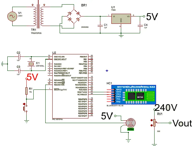
[image:20.612.168.485.194.433.2]divider(potentiometer), Microcontroller(PIC) and Bluetooth circuit to control motor.
Figure 2.1.1: Expected circuit for Ac Power Control Using Smartphone Via Bluetooth
As shown in the figure 2.1, the circuit divided into 2 parts. First part the voltage is
transform and step down to a suitable level for the microcontroller to function as Bluetooth
signal receiver and the motor controller. Furthermore, the servomotor act as a mechanical
actuator to control the position of the potentiometer in the second part. Practically, our
house electrical appliances are supply and support by 240 V of voltage. The second part
of the circuit controls the desired output by the servo motor.
After we build the Bluetooth control apps in smartphone (android based), we can
communication from our smartphone to the PIC controller and command the servo motor
to move desired position and hence the output AC voltage will achieved. The output AC
8
2.2 Demonstration of others Power Control Design
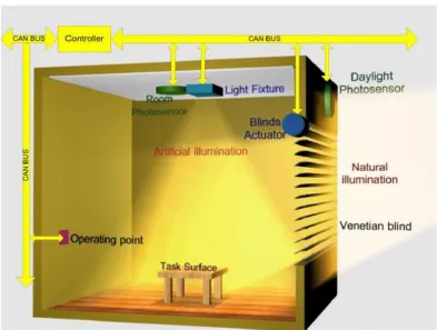
[image:21.612.130.523.144.441.2]2.2.1: Method 1 - An Intelligent Light Control System for Power Saving by Sherif Matta and Syed Masud Mahmud (2009)
Figure 2.2.1.1: System components and physical connectivity
A) System Components:
Controlled Area Network bus, photosensors, AC/DC light bulb, servo motor,
microcontroller
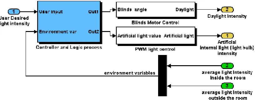
9 Figure 2.2.1.2: System Control Loop
The CAN Bus is to impart all segments. The estimation of room and sunlight
brightening will utilize photosensors. The room photosensor ought not be set in way that
it coordinate light from light sources and in the meantime it gets light from the errand
surface. Average area for the room photosensor is the roof over the assignment surface.
Both room or light photograph sensor can be a gathering of photosensors and by taking
the normal among the whole gathering better exact readings can be acquired. The venetian
blinds actuators are utilized to control the blinds edge to pass sunshine or to piece it. The
light force required is balanced by means of the working point unit. The inside light source
can be a DC or AC lights. DC lights are typically controlled by means of PWM signs to
convey a particular measure of force without squandering any vitality in detached resistors.
Air conditioning lights are controlled by means of thyristors to cut a part of the AC wave
and consequently convey the predefined measure of vitality required for the fancied
brightening. The fundamental controller speaks with alternate parts through the CAN
transport.
The controller and logic handle pieces are dependable to gather all the approaching
environment factors including light power outside the room (sunlight), light force inside
the room (light) lastly the client input. The controller will handle every one of the sources
of info and will be capable to give the best answer for light up the stay with the minimum
10 enlightenment, the controller will first check how much light can be gotten from the
sunlight. On the off chance that it is sufficient notwithstanding for little commitment, the
controller will begin to open the venetian blinds to bring a part of the sunlight inside. In
the event that the sunshine commitment is insufficient to fulfill the client necessities, the
controller will incompletely utilize the fake (light) as a collaborator source to fulfill the
sought light level. The controller will go about as the basic leadership piece. In addition,
the controller will handle all CAN messages. Venetian blinds engine control piece is
mindful to change the venetian visually impaired edge; it contains a controller and an
engine driver enhancer to supply energy to the engine.
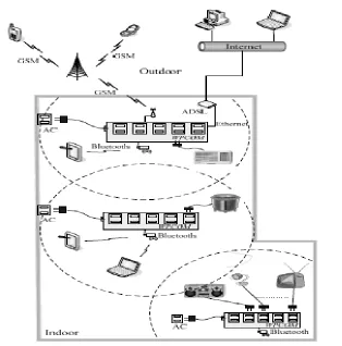
[image:23.612.180.494.302.620.2]2.2.2: Method 2- Remote-Controllable Power Outlet System for Home Power Management by Chia-Hung Lien, Ying-Wen Bai, and Ming-Bo Lin (2007)
Figure 2.2.2.1: Remote-controllable power outlet system.
11 Bluetooth module, Ethernet module, Microcontroller, GSM module and SD Card
module.
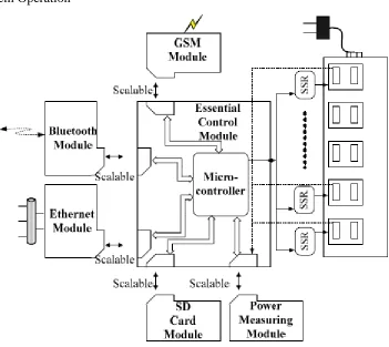
[image:24.612.172.523.142.455.2]B) System Operation
Figure 2.2.2.2: The complete block of the WPCOM.
An AC electrical plug comprising line one end and couple of attachments outlet
on other. The WPCOM associated with an AC electrical plug is comprised of numerous
AC control attachments, an Essential Control Module, a Bluetooth Module, a GSM
Module, an Ethernet Module, a SD Card Module and a Power Measuring Module. The
total piece of the WPCOM is appeared in Fig. 2.2.2.2.
The utilization of Solid State Relays (SSR) to switch every attachment are connect
to electric home machine. SSR have been used to supplant mechanical transfers as a result
of their many points of interest, including scaled down design, disposal of contact skip,
low-vitality utilization, diminished electrical clamor, similarity with advanced hardware