UNIVERSITI TEKNIKAL MALAYSIA MELAKA
ROBOTIC ARM AND CONVEYOR CONTROLLER
This report submitted in accordance with requirement of the Universiti Teknikal Malaysia Melaka (UTeM) for the Bachelor Degree of Electronic Engineering
Technology (Industrial Electronics) with Hons.
by
MUHAMMAD FIRDAUS BIN ZAINAL
B071110011
891119-14-6093
UNIVERSITI TEKNIKAL MALAYSIA MELAKA
BORANG PENGESAHAN STATUS LAPORAN PROJEK SARJANA MUDA
TAJUK: ROBOTIC ARM AND CONVEYOR CONTROLLER
SESI PENGAJIAN: 2014/15 Semester 2
Saya MUHAMMAD FIRDAUS BIN ZAINAL
mengaku membenarkan Laporan PSM ini disimpan di Perpustakaan Universiti Teknikal Malaysia Melaka (UTeM) dengan syarat-syarat kegunaan seperti berikut:
1. Laporan PSM adalah hak milik Universiti Teknikal Malaysia Melaka dan penulis. 2. Perpustakaan Universiti Teknikal Malaysia Melaka dibenarkan membuat salinan
untuk tujuan pengajian sahaja dengan izin penulis.
3. Perpustakaan dibenarkan membuat salinan laporan PSM ini sebagai bahan pertukaran antara institusi pengajian tinggi.
4. **Sila tandakan ( )
SULIT
TERHAD
TIDAK TERHAD
(Mengandungi maklumat yang berdarjah keselamatan atau kepentingan Malaysia sebagaimana yang termaktub dalam AKTA RAHSIA RASMI 1972)
(Mengandungi maklumat TERHAD yang telah ditentukan oleh organisasi/badan di mana penyelidikan dijalankan)
(TANDATANGAN PENULIS)
Alamat Tetap:
NO. 50, Jalan TU 30,
Taman Tasek Utama,
75450 Ayer Keroh, Melaka.
Tarikh: ________________________
Disahkan oleh:
(TANDATANGAN PENYELIA)
Cop Rasmi:
Tarikh: _______________________
iv
DECLARATION
I hereby, declared this report entitled “Robotic Arm and Conveyor Controller” is the results of my own research except as cited in references.
Signature : ……….
Author’s Name : MUHAMMAD FIRDAUS BIN ZAINAL
v
APPROVAL
This report is submitted to the Faculty of Engineering Technology of UTeM as a partial fulfillment of the requirements for the degree of Bachelor of Electronic Engineering Technology (Industrial Electronics) with Hons. The member of the supervisory is as follow:
vi
ABSTRAK
vii
ABSTRACT
viii
DEDICATION
This project and research work is dedicated to my beloved parents for their devoted caring throughout my life, my loving brother and sisters also my friends for their
ix
ACKNOWLEDGEMENT
First of all, I would like to express my sincere thanks and indebted to En Khairul Azha Bin A. Aziz as my supervisor, thank you very much for accepting me as one of your PSM student and the collaborative leadership that you show will always I remembered. I also would like to thank to my PSM panel En. Ir Nik Azran B Abd Hadi and Pn.Izadora Bt Mustaffa who gave me idea on my project.
I would like to express my special thanks and a very down to earth and full with sense of humor-great experience to the Faculty of Engineering Technology (FTK) on putting into practice the Final Year Project as a compulsory chore for the 4th year students prior to complete their course.
I also wish to extend heartfelt thanks to my friends Hirul Mushriff, Nizam, Nurhadzmi, Afiq, Asyraf and my entire classmate for your help and support during this three years in University Technical Malaysia Melaka. The memory we spent together will not I forget.
Finally, I wish to thank to my lovely parents and my siblings, I love you all so much and also to my lectures and friends for their encouragement, strength and support.
x
TABLE OF CONTENT
Abstrak i
Abstract ii
Dedication iii
Acknowledgement iv
Table of Content v
List of Tables vi
List of Figures vii
List Abbreviations, Symbols and Nomenclatures viii
CHAPTER 1: INTRODUCTION 1
1.1 Robot 1
1.2 Robot Arm 2
1.3 Introduction of Project 2
1.4 Objective Project 2
1.5 Problem Statement 3
1.6 Scope of Project 3
CHAPTER 2: LITERATURE REVIEW 4
2.1 Introduction 4
2.2 Previous Project 4
2.2.1 Robotic Arm 5
2.2.2 Robotic Arm with Image Processing 6
2.3 Robotic Arm 8
2.3.1 Robotic Arm Kinematics 8
2.4 Microcontroller 10
2.4.1 PIC Microcontroller 11
xi
2.4.1.1 Variants 13
2.5 RS 232 Serial Port 14
2.6 MATLAB (Graphical User Interface) 15
2.6.1 General Definition of GUI 16
2.6.2 MATLAB GUI 17
2.6.3 MATLAB GUIDE 18
2.6.4 Two Basics in Process of implementing a GUI 18
2.6.5 Designing Graphical User Interface 18
CHAPTER 3: METHODOLOGY 20
3.1 Project Planning 20 3.2 Gannt Chart 22 3.3 Project Cost Planning 23 3.4 Hardware Implementation 24 3.4.1 IC Voltage Regulator 24 3.4.2 Microcontroller PIC 16F877A 25 3.4.3 Fabrication process for PIC microcontroller circuit 27 3.4.3.1 Design circuit using Proteus 7 Professional 27 3.4.3.2 Violet light emission process 27 3.4.3.3 Developing Process 31 3.4.3.4 Etching Process 31 3.4.3.5 Drilling Process 33 3.4.4 Installing the component on PCB board 33 3.4.5 Soldering Process 36 3.4.6 RS 232 Serial Communication 37 3.4.7 RS 232 Configuration 39 3.4.8 Power Supplies for Digital Circuits Review 41
3.4.9 Servo Review 42
3.5 Software Implementation 42
xii
3.5.2 Development of MATLAB GUI using MATLAB GUIDE 45
3.5.3 Build PIC Programming using PIC BASIC PRO Compiler 49
3.5.3.1 Command PULSOUT 49
3.5.3.2 Command FOR and NEXT 49
3.5.3.3 Command SERIN 50
CHAPTER 4: RESULT & DISCUSSION 51
4.1 Introduction 51 4.2 Introduction to PIC controller circuit 51 4.2.1 Programming using PIC BASIC PRO 52
4.3 Determine the degree of servo motor 54
4.4 Testing serial port connection using PIC and MATLAB 55
4.5 Testing connection from MATLAB to robotic arm 55 4.6 Testing circuit to robotic arm and conveyor 58 4.7 Project Prototype Design 59 4.7.1 Building Robotic Arm 59
4.7.2 Project Prototype: Robotic Arm and Conveyor 60
4.8 Troubleshooting and Maintenance 62 4.8 Maintenance and provide proper report 62 CHAPTER 5: CONCLUSION & FUTURE WORK 62
5.1 Conclusion 62 5.2 Problems 63 5.3 Recommendation 63 5.3.1 Hardware Improvement 63
5.3.2 Software Improvement 64
REFERENCES 65
APPENDICES A
xiii
LIST OF TABLES
2.1 RS232 pin assignments (DB9 PC signal set) 14
3.1 Pin connection of PIC16F877A for servo motor speed control system
26
3.2 Basic MATLAB GUI component 46
4.1 Servo motor rotation at specified PULSOUT 53
xiv
LIST OF FIGURES
2.1 Robotic arm 5
2.2 Robotic Arm with image Processing 6
2.3 Robotic arm design 8
2.4 Forward kinematics scheme 9
2.5 Inverse kinematics scheme 9
2.6 PIC Microcontroller 12
2.7 PIC 16F877A Pinout Diagram 13
2.8 Handshake looping a PC serial connector 15
2.9 MATLAB Interface 16
2.10 GUIDE layout of a wavelet analysis GUI 19
2.11 Completed GUI 19
3.1 Project Flowchart 21
3.2 IC LM7805 & LM 7807 24
3.3 Schematic circuit for power supply 25
3.4 Power supply circuit design on stripboard 25
3.5 Schematic circuit of PIC16F877A 27
3.6 PIC Circuit Design on Proteus software 28
3.7 PCB layout in Proteus Software 28
3.8 UV light machine 29
3.9 Mask that is used to transfer circuit to UV board. 29
3.10 UV exposing process 30
3.11 Developing tank and blower 31
3.12 Etching Machine 32
3.13 Etching Solution and Container 32
3.14 Drill bit used for drilling hole on PCB 33
3.15 Resistor 34
3.16 Crystal Oscillator 34
xv
3.18 LED 35
3.19 PIC 16F877A 35
3.20 LM7805 & LM 7807 36
3.21 Soldering station and solder 36
3.22 PCB board after soldering process 37
3.23 Component Placement on box 37
3.24 NRZ (Non Return to Zero) format data 31 38
3.25 RS232 connection 39
3.26 Connection PIC to PC through RS232 Serial Cable 40
3.27 COM port name on Device Manager 41
3.28 Servo motor connection 42
3.29 Flowchart of robot movement 44
3.30 Flowchart of the MATLAB programming 45
3.31 MATLAB GUIDE layout 46
3.32 Property Inspector 47
3.33 Example of GUI 48
3.34 Example of code in m-files 48
3.35 Example of PULSOUT command for controlling servo motor 49 3.36 Example of FOR and NEXT command in programming 50
3.37 Example of SERIN command in programming 51
4.1 PCB layout for PIC circuit 51
4.2 Coding to control robotic arm 52
4.3 Block diagram for testing RS232 connection using LCD Display 54
4.4 MATLAB Program with output on LCD 54
4.5 GUI for this project 55
4.6 Project data flow model. 55
4.7 MATLAB GUI testing to robotic arm 56
4.8 GUI for testing joint movement 57
4.9 Connection from PIC to Robotic Arm 57
4.10 Robotic Arm 58
xvi
4.12 Conveyor 59
4.13 Robotic Arm Component 59
4.14 Robotic Arm 60
4.15 Robotic Arm with control box 60
4.16 Robotic Arm Placement on Conveyor 61
xvii
LIST OF ABBREVIATIONS, SYMBOLS AND
NOMENCLATURE
DOF - Degree of Freedom GUI - Graphical User Interface
IC - Integrated Circuit
I/O - Input / Output
PWM - Pulse Width Modulation
PIC - Programmable Integrated Circuit
PBP - PIC BASIC PRO
PROM - Programmable Read-Only Memory RAM - Random Access Memory
ROM - Read-Only Memory SCI - Serial Connection Interface
1
1.1 Robot
Robot is widely used in the industries. This is happen because the cost to operate a robot to do a certain work is much more less than the cost to pay human labour for the same task. On top of that, the robot can do a quick work with high accuracy that is can’t be accomplished when using human labour once it is programmed. As we all know, the human labour is more versatile compared to robot because human aren’t programmed to do one task only. They can switch their task easily with an order from their supervisor. Robot on the other hand is more specific to one task that is programmed to it. That is why robot has a very high accuracy to do same thing for long period of time. To change the robot job task, first it needs to be reprogrammed that is surely consume time. (Richard D. Klafter, Thomas A. Chmielewski, Michael Negin, 1989, 41).
Today’s robot is like a catalyst to an industrial world. It will evolve. By looking at today’s technology is can’t be denied that today robot can evolve. The robot will become more human as time passes by. It may become more versatile and can switch job easily like human labor nowadays. Maybe it our time, personal computer is quite a technology that everyone has to have. In the future it is not possible that personal robot may be the technology that everyone has to have. To help them do chores and do shopping for them. (Richard D. Klafter, Thomas A. Chmielewski, Michael Negin, 1989, 41).
INTRODUCTION
2
1.2 Robot Arm
The simplest robotic arm is the Cartesian robot or pick and place type. In this case the parts are moved from one location to a conveyor without caring how the part is going to be handled. However, these days robot is much more advance. It can be design and program to handle such fragile and sensitive object without any damage. It can be used to assemble little part in the electronic board or fit them into clamps and fixture. This is possible because of the high accuracy of the robotic arm.
1.3 Introduction of project
This final project is about designing a robotic arm and conveyor controller using MATLAB. The robot will move, grab an object and place it on the conveyor. The project focuses on MATLAB software that will be used to control the robotic arm and the conveyor. To control the movement of the robotic arm, 3 servo motor will be used as a joint. For this particular case, the PIC microcontroller that is used to control the servo motor is programmed. This project used MATLAB software as a base to control the robotic arm and the conveyor.
1.4 Objective Project
3
1.5 Problem Statement
Nowadays robotic controller is lack or function. Sometimes the robot needed to do extra function other than pick and place item. Robotic Arm also can’t recognize item that they grip. With the help of MATLAB, this is possible. The MATLAB software is very powerful software that can do many functions such as image processing. The common robotic controller is using console. The MATLAB GUI offers a better control because the GUI can be design to make the interface user friendly. It also can be very flexible because it can be used in any device that can support MATLAB GUI.
1.6 Scope of Project
The scope of this project includes develop a controller circuit using PIC16F877A to control the robotic arm and conveyor. Servo motor is used for robotic arm’s joint is controlled using MATLAB. MATLAB software is used to control the PIC microcontroller circuit that is connected to robotic arm using RS232 Serial Cable. This project was started with designing a PIC Microcontroller Circuit to control the servo motor and conveyor. The circuit will be designed and put to test to see whether the circuit is running smoothly.
The next stage is deciding what type of robotic arm that will be used for this system. The robotic arm will have 6 joint to be able to move and pick item and place it on the conveyor.
4
2.1 Introduction
The research conducted on previous theses, journals, articles, research papers and other sources will be presented in this chapter. The main idea of literature review is to obtain enough relevant information and knowledge on similar projects done by others. A few projects done previously by students and researchers will be discussed here.
2.2 Previous Project
For the past years, many have attempted to design, create and construct robotic arms using different approaches. Many have tried to create a robotic arm controller using other software and it’s GUI. Many types of robotic arm design can be seen. The projects have its own pros and cons. Stated below is some of the projects which are closely related to the concept of a robotic arm and its controller.
LITERATURE REVIEW
5
2.2.1 Robotic Arm
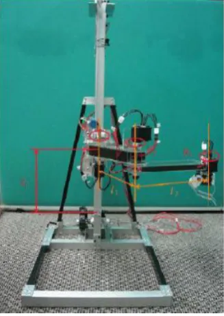
Figure 2.1: Robotic arm
This project was created in 2010 by an undergraduate student from UTM. The objective of the project is to build four degrees of freedom (4DOF) robot arm with Self Compliant Automatic Robot Assembly (SCARA) geometry to perform the motion of pick-and-place for the purposes of education and research. A graphical User Interface (GUI) is also included in this project in order to provide the interaction between the robotic arm and the user (Yong Shen Goh, 2010, 1-2).
[image:21.595.210.374.120.351.2]6 Although this project look smart, but there are some improvements that can be done to the project in order to make it looked smarter. Firstly, it is suggested that the mechanical hardware need to provide a precise dimension of the mechanical hardware. This mechanical part is lack of accuracy because of the dimension and the structure is a handmade mechanical hardware. The use of handmade may reduce the cost, but this result in the lack of the accuracy. Second part to improve is the actuator of the robot. DC motor can be used as an actuator for this robot instead of servomotor since there are many academic researches on it. So, DC motor can replace the servomotors but for my project, the DC motor will be used to control the conveyor instead of the robotic arm.
Last but not least are the sensors. The accelerometer can be placed on the robot to provide additional information for each joint at the robotic arm. The camera or ultrasonic sensor can be placed to be an extra function to the robot as to detect and identified object. This will be the future development of my project. To be integrated with other function other than pick and place item that is robotic arm basic function.
2.2.2 Robotic Arm with Image Processing
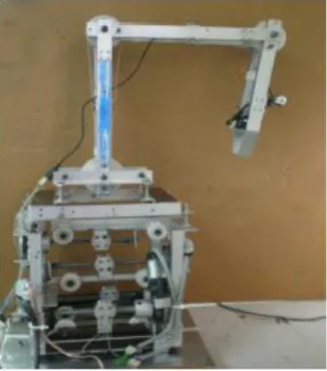
[image:22.595.207.390.517.724.2]7 Figure 2.2 shows that the Self Compliant Automatic Robot Assembly (SCARA) robotic arm that was conducted in 2009. The objective for this project is to build six degree of freedom (6DOF) of robot arm that can sufficiently emulate human arm movement. To aid the robotic arm when doing work to help humans do chores, an image processing function is added. Learn the object criteria is the main purpose of this robotic arm. The robotic arm will be using image processing function system and the data will be stored for future reference. (Men Wee Sam, 2009, 1-2).
The image processing system that gain image from the camera is used to extract data from the image of an object and its feature. This helps the robot to recognize the object. The robotic arm will also learn in real time, where it will recognize more and more objects and do classification based on object features. This aspect of function will be using artificial intelligence specifically neural network. The GUI that include several control panel is used to monitor the robotic arm status. The control panel will give and receive information from robotic arm and from there, the information will be analyze for improvement. (Men Wee Sam, 2009, 2-4).
However, there is some disadvantage on the hardware design. The use of string push pull mechanism proves to be clumsy and time consuming in construction. By using gear drive system or using commercially available advanced motor (digital servo, stepper) will be much of the improvement. But, this will potentially increases the cost of the project dramatically. Then, for further improvement is about the PCB board for the embedded microcontroller. The better PCB will actually improve the circuit stability and look more professional if the circuit is soldered using machine. Lastly, for the image processing technique, it must be more advanced. Current blob tracking implementation is still classified as simple task. The host application can be improved to add more functionality such as object recognition. (Men Wee Sam, 2009, 3-5).
8 human is no longer needed like sort the group of item into different conveyor according to its type.
2.3 Robotic Arm
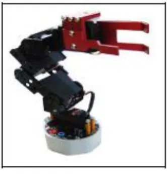
[image:24.595.229.395.307.479.2]The robotic arm design is quite similar to this project reference. This robotic arm is quite simple. It is basically a robot to lift objects. More specifically, this is a robot arm with base, shoulder, elbow and wrist joints and end effector. This is where the servo motor will be placed.
Figure 2.3: Robotic arm
2.3.1 Robot Arm Kinematics