Applications of Structural Fire Engineering, 15-16 October 2015, Dubrovnik, Croatia
A COMPONENT-BASED APPROACH TO MODELLING BEAM BOTTOM
FLANGE BUCKLING AT ELEVATED TEMPERATURES
Guan Quan, Shan-Shan Huang, Ian Burgess
University of Sheffield, Department of Civil and Structural Engineering, Sheffield, UK Abstract
In this study, an analytical model of the combination of beam-web shear buckling and bottom-flange buckling at elevated temperatures has been created. This analytical model is able to track the force-deflection path during post-buckling. A range of 3D finite element models has been created using the ABAQUS software. Comparisons have been carried out between the proposed analytical model, finite element modelling and an existing theoretical model by Dharma (2007). Comparisons indicate that the proposed method is able to provide accurate predictions for Class 1 and Class 2 beams, and performs better than the existing model, especially for slender cross-sections. A component-based model has been created based on the analytical model, and will in due course be implemented in the software Vulcan for global structural fire analysis.
KEYWORDS:shear buckling, bottom-flange buckling, component-based model, fire
1 INTRODUCTION
The structural behaviour of real frames observed in the full-scale Cardington Fire Tests (Kirby, 1998, Huang et al., 1999) was very different from that observed from furnace tests on isolated elements. Consequently, an awareness of the importance of performance-based design, which sufficiently considers the interactions between different members in the structure, was generated. However, full-scale fire tests are expensive. To carry out finite-element modelling of an entire structure, including its joints, is computationally demanding. Component methods provide a practical alternative approach to model the joints and their adjacent zones; component-based joint models can be embodied into the global structural analysis.
[image:1.595.180.446.540.715.2]The Cardington fire tests in 1995-96 (Newman et al., 2000) indicated that beam-web shear buckling, as well as beam bottom flange buckling, near to the ends of steel beams, is very prevalent under fire conditions, as shown in Fig. 1.
Fig. 1 Shear buckling and bottom-flange buckling in Cardington fire test (Newman et al., 2000).
influence on the fire resistance of isolated members. However, the local buckling model presented in Elghazouli’s work is based on elastic plate buckling theory (Timoshenko and Gere, 1961), which is not appropriate for representing the buckling behaviour of Class 1 and 2 sections. In this study, an analytical model of the combination of beam-web shear buckling and bottom-flange buckling at elevated temperatures has been created, based on a model due to Dharma, (2007). This model is capable of predicting local buckling behaviour in the post-buckling stage. Together with the assumption that the characteristics of the buckling zone are identical to those of the normal beam in the pre-buckling stage, this analytical model is able to track the complete force-deflection path of the end-zone of the beam from initial loading to post-buckling. A range of 3D finite element models has been created using ABAQUS. Comparisons have been carried out between the proposed analytical model, finite element modelling and Dharma’s model, which indicate that the proposed method gives better predictions overall than Dharma’s model. A component-based model has been created on the basis of the analytical model, and will be implemented into the software Vulcan for global structural fire analysis.
2 DEVELOPMENT OF ANALYTICAL MODEL
The development of the analytical model is explained using a short cantilever I-beam section as an example. By applying different combinations of bending moment and shear force at its end, this model can represent the bucking panel near the end of a beam of any length using its loading and boundary conditions. When the bottom-flange buckling wavelength calculated from Eq. (1) (Dharma, 2007) is shorter than the beam depth, the length of the buckling zone is taken as identical to the Lp calculated from this equation. Otherwise, the length of the buckling zone is capped to the
beam depth.
3/4 1/4
/ 275
0.713
0.7
f E y
p
y w
t k k
d L
f b t
(1)
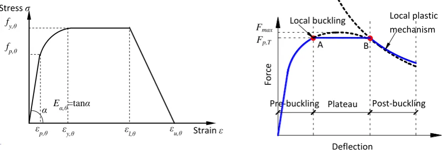
If the material properties, shown in Fig. 2 for steel at temperatures higher than 400°C are used, the vertical force-deflection relationship of the buckling panel can be illustrated qualitatively as Fig. 3. The proposed analytical model divides the loading procedure into three stages: pre-buckling, plateau and post-buckling.
A
Force
Deflection
Pre-buckling Plateau Post-buckling B
Local buckling Local plastic mechanism
[image:2.595.79.527.496.649.2]Fmax
Fig. 2 Stress-strain relationship of structural steel. Fig. 3 Schematic force–deflection of a buckling panel.
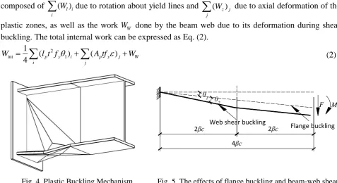
In the pre-buckling stage, the calculation rules follow those for beams at elevated temperatures. The plateau AB occurs when the sectional plastic moment capacity is reached at the middle of the buckling zone. The Point B is the point at which bottom-flange buckling occurs. In the post-buckling stage, it is assumed that the collapse mechanism is composed of a combination of yield lines and plastic yield zones. The plastic buckling mechanism is shown in Fig. 4. The calculation principle is based on equality of the internal plastic work and the loss of potential energy of the external load. The internal plastic work Wint includes the work done by the flanges, which is
Stress σ
Strain ε
fy,θ
fp,θ
α Eα,θ=tanα
εp,θ εy,θ εl,θ εu,θ
composed of ( l i) i
W
due to rotation about yield lines and ( z)j jW
due to axial deformation of the plastic zones, as well as the work WW done by the beam web due to its deformation during shear buckling. The total internal work can be expressed as Eq. (2).2
int 1
1
( ) ( )
4 i p y i j p y j W
[image:3.595.70.548.58.318.2]W
l t f
A tf W (2)Fig. 4 Plastic Buckling Mechanism. Fig. 5 The effects of flange buckling and beam-web shear buckling on beam vertical deflection.
The total deflection of the buckling zone is composed of the deflection caused by simultaneous flange buckling and beam-web shear buckling, as shown in Fig. 5. The influence of bottom-flange buckling is to cause a rotation of the whole beam-end about the top corner of the beam while the effect of shear buckling is a parallel movement of the opposite edges of the shear panel. When applying a shear force and a moment at the end of the buckling zone, the total external work can be expressed by Eq. (3).
1 2 1 2
(4 ) (2 ) ((4 ) (2 ) ) / (4 )
ext i i
W
P F
c F
c M
c
c
c (3)3 VALIDATION AGAINST FINITE ELEMENT MODELLING
3.1 Development of the ABAQUS models
The commercial finite element software ABAQUS was used to simulate the buckling phenomena in the vicinity of beam-column connections at 615°C. The four-noded shell element S4R (Hibbit et al., 2005), which is capable of simulating buckling behaviour, was adopted. A 15mm x 15mm element size was used, after a mesh sensitivity analysis. The Riks approach was used in order to identify the descending curve in the post-buckling stage. Cantilever models with different combination of shear force and bending moment were set up. An image of the ABAQUS model is shown in Fig. 6 (a). All the cantilevers shared the same configuration except for the beam-web thickness. These were varied from 5mm, which is the extreme case for Class 2 beams, to 8mm. The cross-section dimensions are shown in Fig. 6 (b). For each beam configuration, three moment-shear force ratios (M/F), of 500, 1000 and 1500, were applied. A cantilever length identical to twice the beam depth was used, to avoid too high an influence of the boundary conditions on the ABAQUS model and to minimize the influence of the elastic deflection due to bending. The stress-strain relationship of the beam material at 615°C was defined according to Eurocode 3 (CEN, 2005). The details of the material properties used in the ABAQUS models are shown in Table 1.
Table 1 Material Properties
fy,θ (N/mm 2
) εy,θ (%) εt,θ (%) εu,θ (%) Eα,θ (N/mm2)
267.96 2 15 20 1.411×e5
θ1 θ2
F M
Web shear buckling Flange buckling
2βc 2βc
Fig. 6 Finite element model: (a) image of finite element model; (b) cross-section dimension. 3.2 Comparison between the analytical model, Dharma’s model and FEA
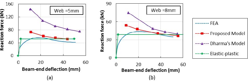
[image:4.595.74.549.439.599.2]The force-displacement relationships given by the proposed analytical model, Dharma’s model and the ABAQUS analysis have been compared. The detailed curves for the two extreme cases, with web thicknesses of 5mm and 8mm, and the moment set at (1000 x the shear force) are shown in Fig. 7. The lines with diamond markers, denoted “Elastic-plastic”, represent the force-deflection relationships when the full plastic moment resistance is reached at the middle of the flange buckling zone. The smooth line without markers represents the result of finite element modelling. The lines with square and triangular markers are the results from the new proposed buckling model and Dharma’s model respectively. It can be seen that the proposed analytical model gives better comparisons to the FE modelling for beams with either 5mm or 8mm webs. Dharma’s model tends to over-estimate the beam capacity considerably for the more slender webs.
Fig. 7 Comparison between the analytical model, Dharma’s model and FE analysis.
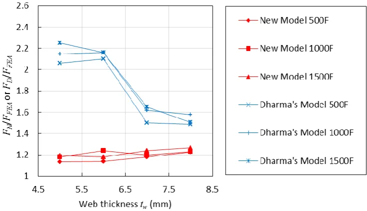
Fig. 8 shows a comparison of the proposed model and Dharma’s model in terms of force-web thickness relationships. The variable FFEA represents the peak load from FE modelling. FNand FD
are the loads from the new analytical model and Dharma’s model respectively, corresponding to the same deflection as FFEA. The vertical axis shows these, normalized with respect to the
corresponding FFEA values. As can be seen from Fig. 8, Dharma’s model tends to over-estimate the
beam loading capacity when the beam-web thickness is 5mm and 6mm, whereas it gives better predictions when the beam-web thicknesses are 7mm and 8mm. The new analytical model is able to give a more stable upper-bound, which is always below 1.3 in terms of load capacity, for both slender and stocky beams within the analysed range, giving a more reliable prediction for the beam’s load-capacity at the post-buckling stage. However, more parametric studies need to be carried out to investigate different factors, or beam configurations, which may influence the accuracy of the results.
163 10
275.5 163 10
tw
2d
d F M
Fig. 8 Comparison between the proposed analytical model and Dharma’s model.
4 COMPONENT-BASED MODEL
One of the major objectives of this research is to develop new components representing beam-web shear buckling and flange-buckling, and implement them with the adjacent joint element, as shown in Fig. 9, to carry out performance-based frame analysis under fire conditions. The flange-buckling component is a zero-length compressive spring, as the effect of the bottom flange buckling is a rotation of the whole cross section. The length of the shear buckling component is non-zero because the effect of shear buckling is a transverse drift, which relies on both the shear-panel length and angle of rotation. The length of the beam-web shear buckling component has been defined as identical to beam depth (d).
Fig. 9 Component-based model for buckling components.
4 CONCLUSIONS
This paper presents a proposed analytical model to predict the post-buckling behaviour of the end-zones of steel beams at elevated temperatures.
A range of finite element models were created using the finite element software ABAQUS. The proposed analytical model was compared with Dharma’s existing model and FE models. The comparison shows that the proposed method provides a stable upper bound in terms of reaction force-deflection relationship within the Class 1 and Class 2 range according to the
B
C C C
C C C C
[image:5.595.95.518.457.638.2]classification method provided by Eurocode 3 (CEN, 2005), while Dharma’s model tends to overestimate post-buckling capacity, especially when the beam web is relatively slender.
The loading resistance of a steel shear panel at elevated temperatures involves three stages: Non-linear pre-buckling, Plateau and Post-buckling. A whole force-deflection relationship has been postulated from initial loading to the post-buckling stage. Component-based models of the beam-web shear buckling and the bottom flange buckling have been created. The newly developed components will be implemented, in conjunction with the adjacent component-based joint element, to carry out performance-component-based analysis of steel and composite framed structures under fire conditions.
REFERENCES
CEN 2005. BS EN 1993-1-2. Design of steel structures. Part 1.2: General rules - Structural fire design. UK: British Standards Institution.
Dharma, R. B. 2007. Buckling behaviour of steel and composite beams at elevated temperatures. Elghazouli, A. & Izzuddin, B. 1999, Significance of local buckling for steel frames under fire
conditions. 4th International Conference on Steel and Aluminium Structures (ICSAS 99), Elsevier Science, 727-734.
Hibbit, D., Karlsson, B. & Sorenson, P. 2005. ABAQUS reference manual 6.7. Pawtucket: ABAQUS Inc.
Huang, Z., Burgess, I., Plank, R. & Reissner, M. 1999. Three-dimensional modelling of two full-scale, fire tests on a composite building. Proceedings of the ICE-Structures and Buildings, 134, 243-255.
Kirby, B. 1998. The behaviour of a multi-storey steel framed building subject to fire attack-experimental data; British Steel Swinden Technology Centre, United Kingdom.
Newman, G. M., Robinson, J. T. & Bailey, C. G. 2000. Fire safe design: A new approach to multi-storey steel-framed buildings, Steel Construction Institute.