Copyright © 2008 by Microsoft Corporation
All rights reserved. No part of the contents of this book may be reproduced or transmitted in any form or by any means without the written permission of the publisher.
Library of Congress Control Number: 2007940507
Printed and bound in the United States of America.
1 2 3 4 5 6 7 8 9 QWT 2 1 0 9 8 7
Distributed in Canada by H.B. Fenn and Company Ltd.
A CIP catalogue record for this book is available from the British Library.
Microsoft Press books are available through booksellers and distributors worldwide. For further infor-mation about international editions, contact your local Microsoft Corporation office or contact Microsoft Press International directly at fax (425) 936-7329. Visit our Web site at www.microsoft.com/mspress. Send comments to [email protected].
Microsoft, Microsoft Press, Active Directory, ActiveX, Internet Explorer, MSDN, Outlook, SQL Server, Visual Basic, Visual Studio, Windows, Windows Media, Windows Server, and Windows Vista are either registered trademarks or trademarks of Microsoft Corporation in the United States and/or other countries. Other product and company names mentioned herein may be the trademarks of their respective owners.
The example companies, organizations, products, domain names, e-mail addresses, logos, people, places, and events depicted herein are fictitious. No association with any real company, organization, product, domain name, e-mail address, logo, person, place, or event is intended or should be inferred.
7KLVERRNH[SUHVVHVWKHDXWKRU¶VYLHZVDQGRSLQLRQV7KHLQIRUPDWLRQFRQWDLQHGLQWKLVERRNLVSURYLGHG without any express, statutory, or implied warranties. Neither the authors, Microsoft Corporation, nor its resellers, or distributors will be held liable for any damages caused or alleged to be caused either directly or indirectly by this book.
Acquisitions Editor:Martin DelRe
Developmental Editor:Karen Szall
Project Editor:Maria Gargiulo
Editorial Production:Interactive Composition Corporation
Technical Reviewer:Bob Hogan; Technical Review services provided by Content Master, a member of CM Group, Ltd.
Cover: Tom Draper Design
iii For David Wright
—Joseph Davies
v
Contents at a Glance
Part I
Addressing and Packet Flow Infrastructure
1
IPv4. . . .3
2
IPv6. . . 29
3
Dynamic Host Configuration Protocol . . . 65
4
Windows Firewall with Advanced Security . . . 89
5
Policy-Based Quality of Service . . . 123
6
Scalable Networking . . . 149
Part II
Name Resolution Infrastructure
7
Domain Name System . . . 169
8
Windows Internet Name Service . . . 207
Part III
Network Access Infrastructure
9
Authentication Infrastructure . . . 231
10
IEEE 802.11 Wireless Networks . . . 297
11
IEEE 802.1X–Authenticated Wired Networks. . . 369
12
Remote Access VPN Connections . . . 417
13
Site-to-Site VPN Connections . . . 499
Part IV
Network Access Protection Infrastructure
14
Network Access Protection Overview. . . 565
15
Preparing for Network Access Protection . . . 589
16
IPsec Enforcement . . . 617
17
802.1X Enforcement . . . 681
18
VPN Enforcement. . . 717
19
DHCP Enforcement . . . 749
vii Microsoft is interested in hearing your feedback so we can continually improve our books and learning resources for you. To participate in a brief online survey, please visit:
www.microsoft.com/learning/booksurvey/
What do you think of this book? We want to hear from you!
Table of Contents
Acknowledgments. . . xxiii
Introduction . . . .xxv
Document Conventions. . . xxv
Reader Aids . . . xxv
About the Companion CD-ROM . . . xxvi
System Requirements. . . xxvii
Technical Support . . . xxvii
Part I
Addressing and Packet Flow Infrastructure
1
IPv4. . . .3
Concepts . . . 3
Network Layers . . . 3
IPv4 Addressing . . . 4
Private IPv4 Addresses . . . 7
Automatic Private IP Addressing (APIPA) . . . 7
Multicast Addresses . . . 8
Network Address Translation . . . 8
Layer 2 and Layer 3 Addressing . . . 10
Layer 4 Protocols: UDP and TCP . . . 12
Planning and Design Considerations . . . 13
Designing Your Internet Connection. . . 13
Creating an IPv4 Addressing Scheme . . . 14
Planning Host Addresses. . . 15
Using VPNs . . . 16
Planning Redundancy . . . 17
Deployment Steps . . . 20
Manually Configuring IPv4 Clients . . . 20
Configuring Client Behavior When a DHCP Server Is Not Available . . . 20
Adding Routes to the Routing Table. . . 21
Ongoing Maintenance . . . 21
Troubleshooting . . . 21
ARP. . . 21
Ipconfig . . . 22
Netstat . . . 23
PathPing . . . 24
Performance Monitor . . . 25
Ping . . . 26
Task Manager . . . 27
Windows Network Diagnostics . . . 27
Chapter Summary . . . 28
Additional Information . . . 28
2
IPv6 . . . 29
Concepts . . . 29
Changes from IPv4 to IPv6. . . 30
IPv6 Addressing . . . 31
IPv6 Autoconfiguration. . . 36
DHCPv6 . . . 39
Neighbor Discovery. . . 39
IPv6 Security . . . 39
IPv6 Transition Technologies . . . 39
Planning and Design Considerations . . . 46
Migrating to IPv6. . . 47
Acquiring IPv6 Addresses . . . 48
Planning Network Infrastructure Upgrades. . . 48
Planning for IPv6 Transition Technologies . . . 49
Deployment Steps . . . 50
How to Disable IPv6 . . . 50
How to Manually Configure IPv6 . . . 51
How to Configure IPv6 from a Script . . . 52
How to Enable 6to4 . . . 54
How to Enable Teredo . . . 55
How to Configure a Computer as an IPv6 Router. . . 56
Ongoing Maintenance. . . 59
Troubleshooting . . . 60
Netsh . . . 60
Ipconfig . . . 61
Nslookup . . . 61
Troubleshooting Teredo . . . 62
Chapter Summary. . . 63
Additional Information . . . 63
3
Dynamic Host Configuration Protocol . . . 65
Concepts . . . 65
The DHCP Address Assignment Process . . . 65
DHCP Life Cycle . . . 67
Planning and Design Considerations . . . 67
DHCP Servers . . . 68
DHCP Relay Agents . . . 68
DHCP Lease Durations. . . 69
Designing Scopes . . . 70
Server Clustering for DHCP . . . 71
Dynamic DNS . . . 71
Deployment Steps . . . 71
DHCP Servers . . . 72
DHCP Relay Agents . . . 80
DHCP Client Configuration. . . 81
Ongoing Maintenance. . . 82
Monitoring DHCP Servers. . . 82
Manually Backing Up and Restoring a DHCP Server . . . 84
Troubleshooting . . . 85
Troubleshooting DHCP Clients . . . 85
Troubleshooting DHCP Servers . . . 85
Using Audit Logging to Analyze DHCP Server Behavior . . . 86
Chapter Summary. . . 86
4
Windows Firewall with Advanced Security . . . 89
Concepts . . . 89
Filtering Traffic by Using Windows Firewall . . . 90
Protecting Traffic by Using IPsec . . . 90
Planning and Design Considerations . . . 95
Planning Windows Firewall Policies . . . 95
Protecting Communications with IPsec . . . 98
Deployment Steps . . . 105
Firewall Settings with Group Policy. . . 105
IPsec Connection Security Rules . . . 112
Ongoing Maintenance . . . 116
Troubleshooting . . . 117
Windows Firewall Logging . . . 118
Monitoring IPsec Security Associations . . . 120
Using Network Monitor . . . 121
Chapter Summary . . . 122
Additional Information . . . 122
5
Policy-Based Quality of Service . . . 123
Concepts . . . 123
The Causes of Network Performance Problems . . . 123
How QoS Can Help . . . 125
QoS for Outbound Traffic. . . 126
QoS for Inbound Traffic . . . 128
QoS Implementation. . . 128
Planning and Design Considerations . . . 128
Setting QoS Goals . . . 129
Planning DSCP Values . . . 129
Planning Traffic Throttling . . . 131
Hardware and Software Requirements. . . 131
Planning GPOs and QoS Policies. . . 132
QoS Policies for Mobile Computers Running Windows Vista. . . 134
Deployment Steps . . . 134
How to Configure QoS by Using Group Policy . . . 134
How to Configure System-Wide QoS Settings . . . 138
Ongoing Maintenance . . . 140
Editing QoS Policies . . . 141
Monitoring QoS . . . 141
Troubleshooting . . . . 143
Analyzing QoS Policies . . . 143
Verifying DSCP Resilience . . . 146
Isolating Network Performance Problems . . . 147
Chapter Summary. . . 148
Additional Information . . . 148
6
Scalable Networking . . . 149
Concepts . . . 149
TCP Chimney Offload . . . 150
Receive-Side Scaling . . . 151
NetDMA. . . 153
IPsec Offload . . . 154
Planning and Design Considerations . . . 155
Evaluating Network Scalability Technologies. . . 155
Load Testing Servers . . . 156
Monitoring Server Performance . . . 157
Deployment Steps . . . 159
Configuring TCP Chimney Offload . . . 160
Configuring Receive-Side Scaling . . . 160
Configuring NetDMA . . . 161
Configuring IPsec Offload. . . 161
Ongoing Maintenance. . . 162
Troubleshooting . . . . 162
Troubleshooting TCP Chimney Offload . . . 162
Troubleshooting IPsec Offload . . . 163
Chapter Summary. . . 164
Additional Information . . . 165
Part II
Name Resolution Infrastructure
7
Domain Name System . . . 169
Concepts . . . 169
DNS Hierarchy . . . 169
DNS Zones. . . 170
Dynamic DNS Updates . . . 171
DNS Name Resolution . . . 172
Planning and Design Considerations . . . 173
DNS Zones . . . 173
DNS Server Placement . . . 174
DNS Zone Replication . . . 176
DNS Security. . . 178
The GlobalNames Zone . . . 179
Deployment Steps . . . 180
DNS Server Configuration . . . 180
DHCP Server Configuration . . . 190
DNS Client Configuration. . . 192
Configuring Redundant DNS Servers . . . 193
Ongoing Maintenance . . . 193
Adding Resource Records. . . 194
Maintaining Zones. . . 194
Automated Monitoring. . . 195
Promoting a Secondary Zone to a Primary Zone. . . 197
Troubleshooting . . . 198
Event Logs. . . 198
Using Nslookup . . . 199
Debug Logging at the Server . . . 201
Using DNSLint . . . 202
Using DCDiag . . . 203
Using Network Monitor . . . 205
Chapter Summary . . . 205
Additional Information . . . 206
8
Windows Internet Name Service . . . 207
Concepts . . . 207
History . . . 207
NetBIOS Names . . . 208
WINS Name Resolution . . . 209
WINS Client Registrations. . . 210
Planning and Design Considerations . . . 211
WINS Server Placement . . . 211
Deployment Steps . . . 213
Configuring a WINS Server. . . 213
Configuring WINS Replication . . . 214
WINS Client Configuration . . . 214
Ongoing Maintenance. . . 217
Backing Up the WINS Server Database . . . 217
Compacting the WINS Database . . . 217
Performing Consistency Checking. . . 218
Monitoring a WINS Server . . . 219
Adding a Static WINS Record . . . 220
Deleting a WINS Record . . . 222
Troubleshooting . . . . 222
Troubleshooting WINS Servers. . . 222
Troubleshooting WINS Clients . . . 224
Chapter Summary. . . 228
Additional Information . . . 228
Part III
Network Access Infrastructure
9
Authentication Infrastructure . . . 231
Concepts . . . 231
Active Directory Domain Services . . . 231
Public Key Infrastructure . . . 235
Group Policy . . . 240
RADIUS. . . 243
Planning and Design Considerations . . . 248
Active Directory . . . 248
PKI. . . 249
Group Policy . . . 251
RADIUS. . . 252
Deployment Steps . . . 260
Deploying Active Directory. . . 260
Deploying PKI . . . 261
Group Policy . . . 269
RADIUS Servers. . . 270
Using RADIUS Proxies for Cross-Forest Authentication . . . 277
Ongoing Maintenance . . . 288
Active Directory . . . 289
PKI . . . 289
Group Policy . . . 289
RADIUS . . . 290
Troubleshooting Tools . . . 291
Active Directory . . . 291
PKI . . . 292
Group Policy . . . 292
RADIUS . . . 292
Chapter Summary . . . 294
Additional Information . . . 294
10
IEEE 802.11 Wireless Networks . . . 297
Concepts . . . 297
Support for IEEE 802.11 Standards . . . 298
Wireless Security . . . 300
Components of 802.11 Wireless Networks . . . 304
Planning and Design Considerations . . . 305
Wireless Security Technologies . . . 305
Wireless Authentication Modes. . . 308
Intranet Infrastructure. . . 309
Wireless AP Placement . . . 311
Authentication Infrastructure. . . 316
Wireless Clients . . . 317
PKI . . . 328
802.1X Enforcement with NAP . . . 332
Deploying Protected Wireless Access . . . 332
Deploying Certificates. . . 332
Configuring Active Directory for Accounts and Groups . . . 334
Configuring NPS Servers . . . 335
Deploying Wireless APs . . . 336
Configuring Wireless Clients . . . 339
Ongoing Maintenance . . . 345
Managing User and Computer Accounts . . . 345
Managing Wireless APs . . . 345
Troubleshooting . . . . 346
Wireless Troubleshooting Tools in Windows . . . 347
Troubleshooting the Windows Wireless Client . . . 355
Troubleshooting the Wireless AP . . . 356
Troubleshooting the Authentication Infrastructure . . . 361
Chapter Summary. . . 367
Additional Information . . . 367
11
IEEE 802.1X–Authenticated Wired Networks. . . 369
Concepts . . . 369
Components of Wired Networks With 802.1X Authentication . . . 369
Planning and Design Considerations . . . 370
Wired Authentication Methods . . . 371
Wired Authentication Modes . . . 374
Authentication Infrastructure . . . 375
Wired Clients. . . 376
PKI. . . 382
802.1X Enforcement with NAP. . . 385
Deploying 802.1X-Authenticated Wired Access . . . 386
Deploying Certificates . . . 386
Configuring Active Directory for Accounts and Groups . . . 388
Configuring NPS Servers . . . 388
Configuring 802.1X-Capable Switches . . . 390
Configuring Wired Clients. . . 392
Ongoing Maintenance. . . 395
Managing User and Computer Accounts . . . 395
Managing 802.1X-Capable Switches . . . 396
Updating Wired XML Profiles . . . 396
Troubleshooting . . . . 397
Wired Troubleshooting Tools in Windows . . . 397
Troubleshooting the Windows Wired Client . . . 402
Troubleshooting the 802.1X-Capable Switch . . . 403
Troubleshooting the Authentication Infrastructure . . . 407
Chapter Summary. . . 413
12
Remote Access VPN Connections . . . 417
Concepts . . . 417
Components of Windows Remote Access VPNs. . . 420
Planning and Design Considerations . . . 421
VPN Protocols . . . 421
Authentication Methods. . . 426
VPN Servers . . . 428
Internet Infrastructure. . . 431
Intranet Infrastructure. . . 433
Concurrent Intranet and Internet Access for VPN Clients. . . 437
Authentication Infrastructure. . . 439
VPN Clients . . . 441
PKI . . . 445
VPN Enforcement with NAP . . . 448
Additional Security Considerations . . . 449
Strong Link Encryption . . . 449
VPN Traffic Packet Filtering on the VPN Server . . . 450
Firewall Packet Filtering for VPN Traffic . . . 450
Multi-Use VPN Servers . . . 460
Blocking Traffic Routed from VPN Clients . . . 462
Concurrent Access . . . 463
Unused VPN Protocols . . . 463
Deploying VPN-Based Remote Access . . . 463
Deploying Certificates. . . 464
Configuring Internet Infrastructure . . . 467
Configuring Active Directory for User Accounts and Groups. . . 468
Configuring RADIUS Servers . . . 469
Deploying VPN Servers. . . 470
Configuring Intranet Network Infrastructure . . . 474
Deploying VPN Clients . . . 477
Ongoing Maintenance . . . 482
Managing User Accounts . . . 482
Managing VPN Servers. . . 483
Updating CM Profiles . . . 485
Troubleshooting . . . 485
Troubleshooting Tools. . . 485
Chapter Summary. . . 496
Additional Information . . . 496
13
Site-to-Site VPN Connections . . . 499
Concepts . . . 499
Demand-Dial Routing Overview . . . 500
Components of Windows Site-to-Site VPNs . . . 505
Planning and Design Considerations . . . 506
VPN Protocols . . . 506
Authentication Methods . . . 510
VPN Routers . . . 511
Internet Infrastructure . . . 515
Site Network Infrastructure. . . 517
Authentication Infrastructure . . . 520
PKI. . . 522
Deploying Site-to-Site VPN Connections . . . 525
Deploying Certificates . . . 525
Configuring Internet Infrastructure . . . 529
Configuring Active Directory for User Accounts and Groups . . . 530
Configuring RADIUS Servers. . . 530
Deploying the Answering Routers . . . 532
Deploying the Calling Routers . . . 538
Configuring Site Network Infrastructure . . . 544
Configuring Intersite Network Infrastructure. . . 546
Ongoing Maintenance. . . 548
Managing User Accounts . . . 549
Managing VPN Routers. . . 549
Troubleshooting . . . . 551
Troubleshooting Tools . . . 551
Troubleshooting Site-to-Site VPN Connections . . . 551
Chapter Summary. . . 561
Additional Information . . . 561
Part IV
Network Access Protection Infrastructure
14
Network Access Protection Overview. . . 565
The Need for Network Access Protection. . . 565
Malware and Its Impact on Enterprise Computing . . . 565
The Role of NAP. . . 571
Business Benefits of NAP . . . 574
Components of NAP . . . 575
System Health Agents and System Health Validators . . . 577
Enforcement Clients and Servers . . . 577
NPS . . . 578
Enforcement Methods. . . 579
IPsec Enforcement . . . 579
802.1X Enforcement . . . 580
VPN Enforcement . . . 580
DHCP Enforcement . . . 580
How NAP Works. . . 581
How IPsec Enforcement Works . . . 582
How 802.1X Enforcement Works. . . 583
How VPN Enforcement Works. . . 584
How DHCP Enforcement Works . . . 585
Chapter Summary . . . 586
Additional Information . . . 587
15
Preparing for Network Access Protection . . . 589
Evaluation of Your Current Network Infrastructure . . . 589
Intranet Computers . . . 589
Networking Support Infrastructure . . . 592
NAP Health Policy Servers . . . 593
Planning and Design Considerations . . . 593
Deployment Steps . . . 596
Ongoing Maintenance . . . 596
Health Requirement Policy Configuration . . . 597
Components of a Health Requirement Policy . . . 597
How NAP Health Evaluation Works . . . 605
Planning and Design Considerations for Health Requirement Policies. . . 609
Remediation Servers . . . 611
Remediation Servers and NAP Enforcement Methods . . . 612
Planning and Design Considerations for Remediation Servers . . . 613
Chapter Summary . . . 614
16
IPsec Enforcement . . . 617
Understanding IPsec Enforcement. . . 617
IPsec Enforcement Logical Networks . . . 618
Communication Initiation Processes with IPsec Enforcement. . . 619
Connection Security Rules for IPsec Enforcement . . . 623
Planning and Design Considerations . . . 625
Active Directory . . . 625
PKI. . . 626
HRAs . . . 631
IPsec Policies . . . 638
NAP Clients . . . 639
Deploying IPsec Enforcement. . . 640
Configuring Active Directory . . . 641
Configuring PKI . . . 641
Configuring HRAs. . . 644
Configuring NAP Health Policy Servers . . . 651
Configuring Remediation Servers on the Boundary Network . . . 654
Configuring NAP Clients . . . 655
IPsec Enforcement Deployment Checkpoint for Reporting Mode . . . 658
Configuring and Applying IPsec Policies . . . 659
Ongoing Maintenance. . . 665
Adding a NAP Client . . . 665
Adding a New SHA and SHV . . . 666
Managing NAP CAs . . . 666
Managing HRAs . . . 667
Troubleshooting . . . . 669
Troubleshooting Tools . . . 669
Troubleshooting IPsec Enforcement . . . 672
Chapter Summary. . . 678
Additional Information . . . 678
17
802.1X Enforcement . . . 681
Overview of 802.1X Enforcement . . . 681
Using an ACL. . . 684
Planning and Design Considerations . . . 686
Security Group for NAP Exemptions. . . 686
802.1X Authentication Methods . . . 686
Type of 802.1X Enforcement . . . 687
802.1X Access Points . . . 687
NAP Clients. . . 688
Deploying 802.1X Enforcement. . . 690
Configuring Active Directory . . . 690
Configuring a PEAP-Based Authentication Method . . . 690
Configuring 802.1X Access Points. . . 691
Configuring Remediation Servers on the Restricted Network . . . 693
Configuring NAP Health Policy Servers . . . 693
Configuring NAP Clients. . . 701
802.1X Enforcement Deployment Checkpoint for Reporting Mode . . . 704
Testing Restricted Access . . . 704
Configuring the Network Policy for Noncompliant NAP Clients for Deferred Enforcement . . . 706
Configuring Network Policy for Enforcement Mode . . . 707
Ongoing Maintenance . . . 708
Adding a NAP Client . . . 708
Adding a New SHA and SHV . . . 708
Managing 802.1X Access Points . . . 709
Troubleshooting . . . 709
Troubleshooting Tools. . . 709
Troubleshooting 802.1X Enforcement . . . 711
Chapter Summary . . . 714
Additional Information . . . 715
18
VPN Enforcement . . . 717
Understanding VPN Enforcement . . . 717
Planning and Design Considerations . . . 720
Use of Network Access Quarantine Control . . . 720
Security Group for NAP Exemptions. . . 721
Types of Packet Filtering . . . 722
VPN Authentication Methods . . . 723
VPN Servers . . . 723
Deploying VPN Enforcement . . . 726
Configuring Active Directory . . . 726
Configuring VPN Servers . . . 727
Configuring a PEAP-Based Authentication Method. . . 727
Configuring Remediation Servers . . . 727
Configuring NAP Health Policy Servers . . . 728
Configuring NAP Clients . . . 735
VPN Enforcement Deployment Checkpoint for Reporting Mode . . . 737
Testing Restricted Access. . . 737
Configuring Deferred Enforcement. . . 739
Configuring Network Policy for Enforcement Mode . . . 739
Ongoing Maintenance. . . 741
Adding a NAP Client . . . 741
Adding a New SHA and SHV . . . 741
Troubleshooting . . . . 741
Troubleshooting Tools . . . 742
Troubleshooting VPN Enforcement. . . 744
Chapter Summary. . . 747
Additional Information . . . 747
19
DHCP Enforcement . . . 749
Understanding DHCP Enforcement . . . 749
Planning and Design Considerations . . . 752
Security Group for NAP Exemptions . . . 752
DHCP Servers . . . 753
NAP Health Policy Servers . . . 753
Health Requirement Policies for Specific DHCP Scopes . . . 754
DHCP Options for NAP Clients. . . 754
DHCP Enforcement Behavior When the NAP Health Policy Server Is Not Reachable. . . 754
NAP Clients . . . 754
Deploying DHCP Enforcement . . . 756
Configuring Remediation Servers . . . 756
Configuring NAP Health Policy Servers . . . 757
Configuring NAP Clients . . . 761
Configuring DHCP Servers . . . 763
Testing Restricted Access . . . 767 Configuring Deferred Enforcement . . . 769 Configuring Network Policy for Enforcement Mode . . . 769 Ongoing Maintenance . . . 771 Adding a NAP Client . . . 771 Adding a New SHA and SHV . . . 771 Troubleshooting . . . 772 Troubleshooting Tools. . . 772 Troubleshooting DHCP Enforcement . . . 774 Chapter Summary . . . 777 Additional Information . . . 777
Glossary . . . 779
Index. . . 793
Microsoft is interested in hearing your feedback so we can continually improve our books and learning resources for you. To participate in a brief online survey, please visit:
www.microsoft.com/learning/booksurvey/
xxiii
Acknowledgments
Joseph Davies and Tony Northrup would like to thank the numerous Windows Server 2008 product team members and other experts at Microsoft who have contributed hundreds of hours of their valuable time toward this project by carefully reviewing chapter content for technical accuracy, by contributing content, and by tirelessly giving us their advice, encouragement, and support as we worked on this project.
We would in particular like to express our thanks to the following contributors at Microsoft for writing the Direct from the Source sidebars that provide in-depth information that only these experts could know (in order by chapter):
■ Dmitry Anipko, a developer in the Windows Core Networking Group
■ Sean Siler, an IPv6 program manager in the Windows Core Networking Group
■ Santosh Chandwani, the lead program manager in the Enterprise Networking Group
■ Ian Hameroff, the senior product manager in Security and Access Product Marketing
■ Gabe Frost, the product manager of Windows Core Networking
■ Rade Trimceski, the program manager of the Windows Networking and Devices Group
■ Jeff Westhead, a senior software development engineer in the Enterprise Networking Group
■ Anthony Witecki, a senior consultant in Microsoft Services, Public Sector
■ Chris Irwin, a premier field engineer in the Premier Field Engineering Group
■ Clay Seymour, a support escalation engineer in Enterprise Platform Support
■ Tim Quinn, a support escalation engineer in Enterprise Platform Support
■ James McIllece, a technical writer in the Windows Server User Assistance Group
■ Samir Jain, a lead program manager in the India Development Center
■ Greg Lindsay, a technical writer in the Windows Server User Assistance Group
■ John Morello, a senior program manager in the Windows Server Customer Connection Group
We wrote this book while Windows Server 2008 was in development, and many of the most brilliant people at Microsoft reviewed our chapters in rough form to make corrections, alert us to changes in the operating system, and suggest additions. Many thanks to our reviewers (in order by chapter):
Alireza Dabagh, Chandra Nukala, Arren Conner, Jeff Westhead, Sudhakar Pasupuleti, Yi Zhao, Subhasish Bhattacharya, Tim Quinn, Clay Seymour, Chris Irwin, Greg Lindsay, James MacIllece, Anthony Leibovitz, Sreenivas Addagatla, Arvind Jayakar, Brit Weston, Lee Gibson, Drew Baron, Brit Weston, Dhiraj Gupta, Samir Jain, Puja Pandey, Tushar Gupta, Manu Jeewani, Jim Holtzman, Kevin Rhodes, Steve Espinosa, Tom Kelnar, Kedar Mohare, Pat Fetty, Gavin Carius, Wai-O Hui, Harini Muralidharan, Richard Costleigh, Ryan Hurst, Chris Edson, Chandra Nukala, Abhishek Tiwari, Aanand Ramachandran, John Morrello, and Barry Mendonca.
Additional thanks go to the Microsoft Security Review Board for their careful review of all the content in this book.
If we’ve forgotten to include anyone in the above list, please forgive us!
Joseph would like to personally thank and honorably mention Greg Lindsay for devoting his time and effort of many hours for meetings, discussions, technical review, and multiple sidebars for the Network Access Protection (NAP) chapters of this book.
Tony would also like to personally thank Bob Hogan for going above and beyond what was required of him as a technical editor, and Hayley Bellamy for assistance troubleshooting a crit-ical hardware problem.
Finally, we would also like to collectively thank our outstanding editorial team at Microsoft Press for this project, including Martin DelRe, Jenny Moss Benson, Maureen Zimmerman, and Maria Gargiulo, and Susan McClung, Joel Rosenthal, Bob Hogan, Mary Rosewood, and Seth Maislin of Interactive Composition Corporation, for their unflagging energy and tireless commitment to making this book a success.
xxv
Introduction
Welcome to Windows Server 2008 Networking and Network Access Protection (NAP). You can use the deployment guidelines in Part I of this book to build an addressing and packet flow infrastructure that uses Internet Protocol version 4 (IPv4) and Internet Protocol version 6 (IPv6), Dynamic Host Configuration Protocol (DHCP), host-based firewalling and Internet Protocol security (IPsec), policy-based Quality of Service (QoS), and scalable networking technologies.
You can use the deployment guidelines in Part II of this book to build a name resolution infra-structure with the Domain Name System (DNS) and Windows Internet Name Service (WINS).
You can also use the guidelines in Part III of this book to deploy a network access infrastruc-ture consisting of Active Directory domain services, a public key infrastrucinfrastruc-ture, Group Policy, and centralized authentication, authorization, and accounting with Remote Authentication Dial-In User Service (RADIUS). This network access infrastructure supports a variety of authenticated and authorized network access methods, including Institute of Electrical and Electronics Engineers (IEEE) 802.11 wireless, authenticating switch, and virtual private network (VPN) connections.
Once your addressing and packet flow, name resolution, and network access infrastructures are in place, you can use the guidelines in Part IV of this book to deploy Network Access Protection (NAP) to enforce system health requirements for IPsec-protected communication, IEEE 802.1X–authenticated wireless and wired access, remote access VPN connections, and DHCP address configuration.
Document Conventions
The following conventions are used in this book to highlight special features or usage:
Reader Aids
The following reader aids are used throughout this book to point out useful details:
Reader Aid Meaning
Note Underscores the importance of a specific concept or highlights a special case that might not apply to every situation.
More Info Refers you to another resource for further information.
Sidebars
The following sidebars are used throughout this book to provide added insight, tips, and advice concerning networking and network access protection (NAP):
Command-Line Examples
The following style conventions are used in documenting command-line examples through-out this book:
About the Companion CD-ROM
The companion CD-ROM included with this book contains the following:
■ eBook form of this book Adobe Portable Document Format (PDF) version of this book, which allows you to view it online and perform text searches.
■ eBook of TCP/IP Fundamentals for Microsoft Windows The most current version of TCP/IP Fundamentals for Microsoft Windows is available at http://technet.microsoft .com/en-us/library/bb726983.aspx. Adobe PDF version of TCP/IP Fundamentals for Microsoft Windows by Joseph Davies.
■ eBook of Understanding IPv6, Second Edition Adobe PDF version of Understanding IPv6, Second Edition by Joseph Davies.
■ Link to Network Monitor 3.1 Link to Network Monitor 3.1, available as a free download from the Microsoft.com Download Center. You can also install Network Monitor 3.1 from http://go.microsoft.com/fwlink/?LinkID=92844. For the latest information about Network Monitor, see the Network Monitor blog at http://blogs.technet.com/netmon.
Sidebar Meaning
Direct from the Source Contributed by experts at Microsoft to provide “from-the-source” insight into how technologies work, best practices, and trouble-shooting tips.
How It Works Provides unique glimpses of features and how they work.
Style Meaning
Bold font Used to indicate user input (characters that you type exactly as shown).
Italic font Used to indicate variables for which you need to supply a specific value (for example file_name can refer to any valid file name).
Monospace font Used for code samples and command-line output.
Find Additional Content Online As new or updated material becomes available that complements your book, it will be posted online on the Microsoft Press Online Windows Server and Client Web site. Based on the final build of Windows Server 2008, the type of material you might find includes updates to book content, articles, links to companion content, errata, sample chapters, and more. This Web site will be available soon at
http://www.microsoft.com/learning/books/online/serverclient and will be updated periodically.
System Requirements
To view the eBooks, you need any system that is capable of running Adobe Reader, available from http://www.adobe.com. For more detailed information about system requirements, refer to the System Requirements page in the back of the book.
Technical Support
Every effort has been made to ensure the accuracy of this book and the contents of the companion CD-ROM. Microsoft Press provides corrections for books in the Microsoft Knowledge Base. If you have comments, questions, or ideas regarding this book or the companion CD, please send them to Microsoft Press by using either of the following methods: E-mail: [email protected]
Postal Mail: Microsoft Press
Attn: Windows Server 2008 Networking and Network Access Protection (NAP) Editor One Microsoft Way
Redmond, WA 98052-6399
Part I
3
Chapter 1
IPv4
Today, the vast majority of networked computers communicate using Internet Protocol version 4 (IPv4) and the suite of protocols collectively called Transmission Control Protocol/ Internet Protocol (TCP/IP). To plan, deploy, maintain, and troubleshoot Microsoft Windows networking, you must first understand the fundamentals of TCP/IP.
This chapter provides information about how to design, deploy, maintain, and troubleshoot IPv4 networks. Most of the information in this chapter applies equally to the Windows Server 2008, Windows Vista, and Windows Server 2003 operating systems and other recent versions of Windows. For information about IPv6, refer to Chapter 2, “IPv6.” This chapter assumes that you have a general understanding of TCP/IP and some networking experience.
Concepts
This section provides a brief overview of important TCP/IP concepts, including IPv4 addressing, multicasting, User Datagram Protocol (UDP), and TCP.
Network Layers
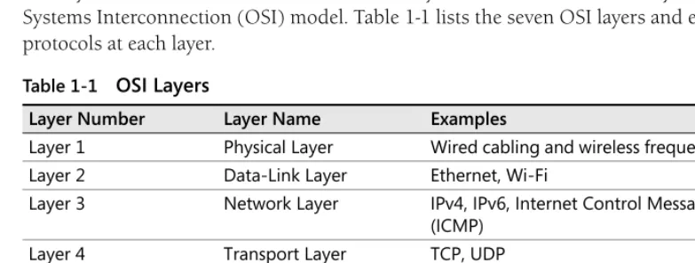
Network protocols are organized into layers, with each layer interacting only with the layers directly above and below it. The most commonly used model is the seven-layer Open Systems Interconnection (OSI) model. Table 1-1 lists the seven OSI layers and examples of protocols at each layer.
[image:31.603.100.492.416.564.2]This chapter focuses on IPv4, a Layer 3 protocol, but also discusses how IPv4 interacts with Layer 2 and Layer 4 protocols.
Table 1-1 OSI Layers
Layer Number Layer Name Examples
Layer 1 Physical Layer Wired cabling and wireless frequency standards Layer 2 Data-Link Layer Ethernet, Wi-Fi
Layer 3 Network Layer IPv4, IPv6, Internet Control Message Protocol (ICMP)
Layer 4 Transport Layer TCP, UDP
Layer 5 Session Layer NetBIOS
Layer 6 Presentation Layer Rarely used
IPv4 Addressing
IPv4 addresses are four bytes, for a total length of 32 bits. (One byte equals eight bits.) Each byte (known as an octet) is written as a decimal number from 0–255 and separated by a period (called a dot when speaking ). For example, the following are valid IP addresses:
■ 192.168.1.32
■ 10.1.1.1
■ 127.0.0.1
[image:32.603.79.475.246.465.2]The beginning portion of an IP address is the network address, and the remainder is the host address, which identifies an individual computer on the subnet. Routers use the network address to forward packets to the correct destination network, and computers use the host address to determine which packets are destined for them. Figure 1-1 illustrates how routers move a packet across a network to the destination computer.
Figure 1-1 IPv4 routing
In Figure 1-1, the first three octets of the IP address are the network address (such as 192.168.1 or 192.168.10), and the last octet is the host address (such as .5 or .10). Although this is the most common way to divide an IP address between the host and network, you can:
■ Use a shorter network address (such as 192.168) to dedicate more bits to the host address. This gives you fewer networks but allows more hosts on each network.
■ Use a longer network address and dedicate fewer bits to the host address. This gives you more subnets but a smaller number of unique hosts on each network.
Processes the packet because the destination
IP address matches a local IP address Forwards packet
toward 192.168.1.0/24 through a neighboring
router
Forwards packet to 192.168.1.10 through
the default gateway
Transmits packet to the destination host, which is on a local network
192.168.1.10
192.168.1.120
192.168.1.230 192.168.1.x
192.168.120.x 192.168.85.x
192.168.24.x 192.168.100.x
192.168.100.5
Packet Packet
Hosts use subnet masks to indicate how many bits of the IP address are dedicated to the network address. The subnet mask 255.255.255.0 indicates that the first three octets of the IP address are dedicated to the network address, and is commonly referred to as a Class C network. The subnet mask 255.255.0.0 indicates that the first two octets of the IP address are dedicated to the network address and is commonly referred to as a Class B network. Though rarely used, a Class A network has a subnet mask of 255.0.0.0 and indicates that only the first octet of the IP address is used as the network address.
Direct from the Source: Network Classifications
The “A,B,C” classful networking is obsolete. Classless Inter-Domain Routing (CIDR), introduced by RFC 1519, is not only about notation, but about how address space is actually split. One of the differences is that in classful networking, a router in the middle can determine the subnet mask given just the address, and thus can determine whether a particular address is a subnet broadcast. In CIDR, in general, only routers directly connected to a subnet can determine the actual subnet mask.
Dmitry Anipko, Developer Windows Core Networking
The subnet mask 255.255.255.0 indicates that the first 24 of the 32 bits in an IP address are dedicated to the network address. Rather than writing the entire subnet mask, you can use Classless Inter-Domain Routing (CIDR, pronounced cider) notation to indicate the number of bits dedicated to the network address by adding a forward slash (/) symbol followed by the number of bits in the network address after the IP address. For example, a 24-bit subnet mask could be written as 192.168.10.0/24. If you wanted to subdivide that network into four smaller networks, you could use a 26-bit network address (leaving only 6 bits for the host address). The four networks would be written as shown in Table 1-2.
Table 1-2 Subdividing the 192.168.10.0/24 Network
Network ID IP Address Range
How It Works: Binary Math
Although IP addresses are expressed in decimal octets, you must use binary math (also known as Boolean math) if you want to use anything other than an 8-bit, 16-bit, or 24-bit subnet mask. For example, consider the IP address 192.168.14.222 with a 24-bit subnet mask, as shown in Figure 1-2. In this example, the network ID and host ID are divided along 8-bit boundaries, making it simple to separate the two in decimal numbering.
Figure 1-2 24-bit subnet mask
Now, consider the same IP address with a 26-bit subnet mask, as shown in Figure 1-3. In this example, the network ID uses the highest two bits from the last octet. Although this is more difficult to visualize in decimal form because the last octet is partially dedicated to the network ID and partially dedicated to the host ID, in binary, the network ID is simply a 26-bit number, whereas the host ID is a 6-bit number.
Figure 1-3 26-bit subnet mask
In Figure 1-3, the network ID would be written as 192.168.14.128/26, and host IP addresses would be in the range 192.168.14.129 to 192.168.14.190. Assigning a host IP address below 128 or above 192 would require changing one of the two highest two bits in the last octet, which would also change the network ID.
If you find this confusing, you’re not alone. IPv4 was designed to support only 8-bit, 16-bit, or 24-bit subnet masks (also known as classful subnet masks). Variable-length subnet masks were added decades later when CIDR was introduced in 1993. IPv6, discussed in Chapter 2, takes a more straightforward approach.
Table 1-3 shows commonly used subnet mask bit lengths, the number of host IP addresses available in each, and the number of subnets you could create if you had been allocated a 24-bit network address space such as 192.168.10.0/24.
1 1
192 168 14 222
Host ID Network ID
0 0 0 0 0 0 1 0 1 0 1 0 0 0 0 0 0 0 1 1 1 0 1 0 0 0 1 0 1 0
1 1
192 168 14 222
Host ID Network ID
Note that the available number of host IP addresses is actually a bit lower than indicated in Table 1-3. The highest and lowest IP addresses on a subnet (in binary, all 0s and all 1s) are reserved for broadcast messages. Additionally, the router will require at least one IP address on the subnet. Therefore, the number of IP addresses available for computers on the network is actually three lower than the theoretical number of IP addresses shown in Table 1-3.
Private IPv4 Addresses
Several IP address ranges are reserved for private use on internal networks, as listed in Table 1-4. Addresses in these ranges cannot be accessed from the public Internet because Internet routers won’t have the addresses in their routing tables. However, private IP addresses can be routed on your internal network, and you can use network address translation (NAT) to allow clients with a private IP address to communicate on the Internet. NAT is discussed later in this chapter.
Private IP addresses are defined in RFC 1918, available at http://tools.ietf.org/html/rfc1918.
Automatic Private IP Addressing (APIPA)
If a computer running Microsoft Windows 98 or a later version of Windows does not have a static IP address configured and cannot obtain an IP address from a Dynamic Host Configuration Protocol (DHCP) server, it will use Automatic Private IP Addressing (APIPA) to assign a random IP address from the link-local address range 169.254.1.0 to 169.254.254.255. APIPA, also known as IPv4 Link-Local (IPv4LL), Zero Configuration Networking, or Zeroconf, is described in RFC 3330 (available at http://tools.ietf.org/html/rfc3330) and RFC 3927 (available at http://tools.ietf.org/html/rfc3927).
APIPA allows computers to communicate on a local area network (LAN), such as an ad-hoc wireless network, without a DHCP server or static IP address configuration. If a computer has an APIPA IP address on a network that has a DHCP server, it means that the computer could not contact the DHCP server. Either the computer is not properly connected to the network, or the DHCP server was offline.
Table 1-3 Subnet Mask Bit Lengths and Available Host IP Addresses
Subnet Mask Bit Length Available Network Addresses Available IP Addresses
24 1 256
25 2 128
26 4 64
27 8 32
Table 1-4 Private IPv4 Address Ranges
Network Available 24-bit Networks Available IP Addresses
192.168.0.0–192.168.255.255 256 65,536
172.16.0.0–173.1.255.255 4,096 1,048,576
Note APIPA addresses should never have a default gateway because APIPA is designed to function only on a single subnet.
Computers with APIPA IP addresses will regularly attempt to contact a DHCP server in case a DHCP server is brought online after the client computer starts.
Multicast Addresses
Addresses in the range 224.0.0.0 through 239.255.255.255 are reserved for multicast communications. Whereas most IP communications are one-to-one (such as a Web browser connecting to a Web server), and some IP communications are broadcast to the local network, such as an Address Resolution Protocol (ARP) request, a relatively small number of
communications are multicast to multiple specific listeners.
Often, multicast communications are sent only to other hosts on the local network. For example, Enhanced Interior Gateway Routing Protocol (EIGRP) uses the multicast IP address 224.0.0.10 to allow a router to communicate with a single packet a change in the routing table to all neighboring routers.
However, multicast communications can also be routed between networks. Routed multicast-ing does not typically work on the Internet; however, private networks can be configured to support multicasting. Private routed multicasting is useful for internal streaming video, for example, to transmit live video of a speech by a company’s president to all employee computers.
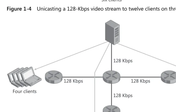
Figure 1-4 shows the bandwidth used when twelve computers use unicasting to view a 128k streaming video feed. Whereas the relatively low bandwidth used in this example would allow most LANs to support unicasting, a network with hundreds or thousands of computers would be able to support only multicasting live video. Figure 1-5 shows that multicasting the streaming video feed uses significantly less bandwidth, especially on the server’s network.
Network Address Translation
Figure 1-4 Unicasting a 128-Kbps video stream to twelve clients on three networks
Figure 1-5 Multicasting a 128-Kbps video stream to twelve clients on three networks
512 Kbps 256 Kbps
768 Kbps 1.5 Mbps
Six clients
Four clients Two clients
128 Kbps 128 Kbps
128 Kbps 128 Kbps
Six clients
[image:37.603.100.436.295.509.2]IPv4 Address Shortage
In theory, 32-bit IP addresses allow for over four billion addresses, and recent estimates place the total number of Internet-connected computers at a little over one billion. The number of IP addresses actually available for client computers is well below four billion because of the large number of private IP addresses, the range of addresses reserved for multicast communications, and the fact that most subnets have well below 100 percent utilization.
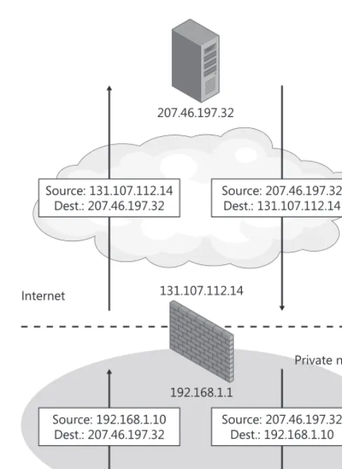
NAT works around the limited number of public IP addresses by allowing computers with private IP addresses to access the Internet. With NAT, you assign private IP addresses (such as 192.168.0.0/16) to computers on your internal network. Your NAT gateway receives a public IP address, intercepts all outgoing connections, and forwards the traffic to the final destination on the Internet. To allow the return traffic to be routed back to your network, the NAT gateway changes the source IP address from the private IP address to its own public IP address. When the NAT gateway receives return traffic, it rewrites the destination IP address to the client computer’s private IP address.
Figure 1-6 illustrates how NAT works. Because NAT changes private IP addresses to its own public IP address before sending packets on the Internet, NAT is completely transparent to most network applications. Configuring clients on a NAT network is exactly the same as configuring clients on any other IPv4 network.
You can configure port forwarding on the NAT gateway to allow clients on the Internet to connect to a server on your private network. With port forwarding, the NAT gateway forwards all incoming packets with a specific destination port number to an IP address on your internal network. For example, you could configure incoming requests with a destination TCP port number of 80 to be sent to your Web server and all incoming requests with a destination TCP port number of 25 to be sent to your e-mail server.
Layer 2 and Layer 3 Addressing
Computers that are on the same LAN identify each other using media access control (MAC) addresses. MAC addresses are Layer 2 addresses and are not routable, whereas IP addresses are Layer 3 and can be routed.
The first step in sending an IP packet is to determine whether the remote host is on the same LAN or a remote network:
■ If the destination is on a remote LAN, the destination MAC address must be the default gateway’s MAC address. The default gateway will then forward the packet to the next network in the route towards the destination.
Figure 1-6 How NAT works
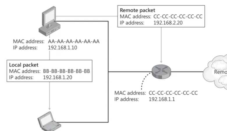
Regardless of whether the destination MAC address is that of the default gateway or the final destination host, the destination IP address will always be the IP address of the final destination host. Figure 1-7 illustrates how addressing of packets for the same LAN or a remote LAN differ. Naturally, the source IP address and the source MAC address are those of the source host.
Note Figure 1-7 uses Ethernet as the model for Layer 2 communications. Other Layer 2 protocols might use a different structure for the MAC address.
192.168.1.10 131.107.112.14
192.168.1.1 207.46.197.32
NAT
Private network Source: 207.46.197.32 Dest.: 131.107.112.14 Source: 131.107.112.14
Dest.: 207.46.197.32
Source: 192.168.1.10 Dest.: 207.46.197.32
Figure 1-7 Addressing at Layers 2 and 3
Hosts use ARP to determine the MAC address of a computer on the local network. ARP uses this process:
1. The client computer broadcasts an ARP message to the LAN asking for the MAC address of the computer with the specified IP address.
2. All computers on the LAN receive and process the ARP request.
3. The server that owns the IP address specified in the ARP request sends a response back with its MAC address.
4. The client receives the ARP response, adds the address to the ARP cache, and uses the server’s MAC address for all future communications.
Layer 4 Protocols: UDP and TCP
Most network applications use one of two Layer 4 protocols:
■ User Datagram Protocol (UDP) Applications that want to minimize network overhead and do not require detecting lost or out-of-order packets use UDP. UDP also supports multicasting, which is not possible with TCP. Most DNS queries and streaming media use UDP. Applications that use UDP can still handle retransmitting lost packets or reordering out-of-order packets; however, it must be handled within the application itself and requires more effort from the application developer.
■ Transmission Control Protocol (TCP) Applications that require detecting and resending lost or corrupted packets use TCP. Using TCP requires a connection to be established before application data can be transmitted. Specifically, the client sends a
MAC address: CC-CC-CC-CC-CC-CC IP address: 192.168.1.1
MAC address: AA-AA-AA-AA-AA-AA IP address: 192.168.1.10
MAC address: BB-BB-BB-BB-BB-BB IP address: 192.168.1.20 Local packet
MAC address: BB-BB-BB-BB-BB-BB IP address: 192.168.1.20
Remote packet
MAC address: CC-CC-CC-CC-CC-CC IP address: 192.168.2.20
SYN packet to request a connection, the server responds with an SYN/ACK packet, and the client confirms the connection with a ACK packet. Requiring these packets to be exchanged before application data can be sent causes TCP to be slower than UDP for short-lived connections. Most applications, including e-mail and Web browsing, use TCP.
A single server typically has several different services listening for incoming connections. To allow Windows to direct incoming traffic to the correct application, incoming network requests include a port number. For example, DNS requests use port 53 by default. Therefore, when Windows receives a packet with a port number of 53, it delivers it to the DNS Server service.
Planning and Design Considerations
It is critical to carefully plan a new IPv4 network, because changing IP addresses after deployment is time consuming. This section guides you through the fundamentals of planning an IPv4 network.
Designing Your Internet Connection
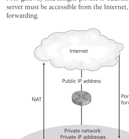
[image:41.603.102.323.360.598.2]Small organizations, or regional offices that can support only a single subnet, can use the architecture shown in Figure 1-8. This architecture assigns a single public IP address to the NAT gateway and assigns private IP addresses to all computers on the internal network. If a server must be accessible from the Internet, the NAT gateway can be configured with port forwarding.
Figure 1-8 Small network architecture without a perimeter network
Public IP address
NAT Port
forwarding
Private network: Private IP addresses
(NAT and DHCP)
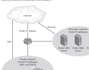
Most medium-size and large organizations will use a network architecture resembling that shown in Figure 1-9. This architecture provides a separate network for public servers, with public IP addresses, called a perimeter network (also known as a screened subnet). Internal clients use private DHCP-assigned IP addresses and access the Internet by using a NAT gateway. In the example shown in Figure 1-9, the private network might consist of many different subnets connected with routers.
Figure 1-9 Medium-size or large network architecture with a perimeter network
Note The network device shown in the center of Figures 1-8 and 1-9 represents routing, firewall, and NAT gateway services. For small organizations, these services are often performed by a single device. Large organizations often have separate redundant devices for each role.
Creating an IPv4 Addressing Scheme
Plan your IPv4 addressing scheme to simplify routing and IP address configuration on your internal network by following these steps. In the long run, this will simplify router configuration and reduce the complexity of troubleshooting network problems.
1. Choose one of the private address ranges for your internal networks. The 10.0.0.0/8 address space provides the largest number of networks.
Public IP address
Routing
NAT
Private network: Private IP addresses
(NAT and DHCP)
Public DNS server
Public Web server
2. Choose a random starting point within the private address space. For example, if you are using the 10.0.0.0/8 address space, you could choose 10.187.0.0/16 for your internal networks. Even though your private address space does not need to be unique on the Internet, using a random portion of the address space will minimize the chance for conflict with other internal networks that you might connect to in the future as a result of mergers, acquisitions, or business partnerships. Many organizations start numbering at the bottom of the address space (such as using networks numbered 10.0.0.0/24 or 192.168.0.0/24), which are likely to conflict with other private networks.
3. Allocate portions of your address space to different regional offices. Provide at least ten times the number of addresses each location is likely to require in the near future to allow for future growth and enable network administrators to use logical network numbering without needing to subnet networks for efficiency.
4. Allow each regional office to subnet that address space for their internal networks. To simplify configuration, use 24-bit subnets for each physical network segment. Figure 1-10 illustrates how a private address can be divided between regional offices and then subdivided for individual network segments. These networks must provide address space for both wired and wireless networks.
5. Allocate network space for remote-access clients such as employees who work from home and dial in or connect using a virtual private network (VPN).
Figure 1-10 Hierarchical addressing
Planning Host Addresses
To improve consistency on your networks and allow administrators to more quickly assess network problems, create a host address plan that you will use on all networks. Whereas the specific servers will vary, Table 1-5 shows a typical host address plan.
10.187.16.0/12 10.187.0.0/16
10.187.17.0/24 10.187.18.0/24 10.187.0.0/20
10.187.1.0/24 10.187.3.0/24
10.187.2.0/24
10.187.32.0/12
10.187.33.0/24 10.187.35.0/24
Using VPNs
Today, many organizations choose to use site-to-site VPNs to connect remote offices across the public Internet. Site-to-site VPNs use the Internet to establish an authenticated, encrypted connection between two remote offices. Traffic originating from one office can travel to the remote office just as if the two offices were connected by standard routers.
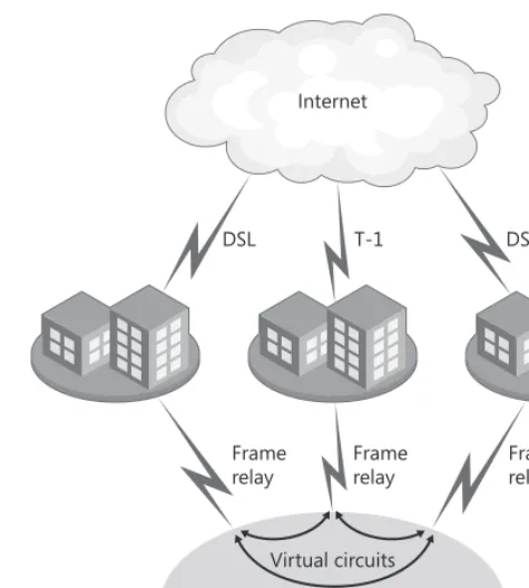
Figure 1-11 illustrates a traditional approach to connecting remote offices, which relies on private network links such as frame relay networks, asynchronous transfer mode (ATM) networks, or private telco links (such as a T-1). This approach provides guaranteed, consistent bandwidth between offices. However, the cost can be high compared to a VPN-based solution because separate network connections are required for the private wide area network (WAN) and the Internet.
Figure 1-12 illustrates a similar network connected using VPNs. Typically, each location requires an Internet connection anyway, meaning that no additional network links are required to implement the VPN. However, VPNs must share bandwidth with other Internet traffic. Additionally, the performance of communications across the Internet can vary more than in private network links.
Note Although encryption provides a high level of privacy for VPN data, using a public network to transport private data might not meet some security regulations.
Many firewalls and routers have VPN capabilities built in. Additionally, you can implement a VPN with dedicated network hardware or any recent version of Windows Server, including Microsoft Windows 2000 Server, Windows Server 2003, and Windows Server 2008.
Therefore, you can often implement VPNs with little or no additional cost.
Table 1-5 Example Host Address Plan
Role Host Address
Default gateway .1
Secondary gateway .2
DHCP server .3
Primary DNS server .4
Secondary DNS server .5
Primary Windows Internet Name Service (WINS) server .6
Secondary WINS server .7
Clients that temporarily require a static IP address .20–.29
Static clients .30–.99
Figure 1-11 A WAN built with dedicated, private network links
Figure 1-12 A WAN built with VPNs
Planning Redundancy
Your routing infrastructure is the most critical part of your network because without it, all network services are unavailable. Because of this, many environments deploy redundant router configurations. Fortunately, IPv4 was designed for redundancy.
Frame relay network Virtual circuits
Frame relay
Frame relay Frame
relay
DSL T-1 DSL
Internet
DSL T-1 DSL
Internet
Routers use routing protocols to create a map of the network. They then use this map to build their own routing tables, which allows them to properly forward traffic that is destined for a network not directly connected to the router. If there is more than one path to a destination network, routers can automatically detect the failure of one path and redirect traffic through a functioning path.
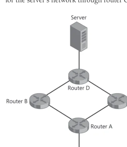
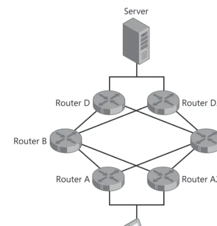
[image:46.603.84.287.168.402.2]Consider the network shown in Figure 1-13. If router B fails, the client can still communicate with the server because router A will detect the failure of router B and forward traffic destined for the server’s network through router C.
Figure 1-13 Redundant network
However, the network shown in Figure 1-13 still has single points of failure: routers A and D. If one of these routers fails, computers that have the failed router configured as their default gateway will be unable to communicate with hosts on other networks.
Figure 1-14 demonstrates that you can provide redundant default gateways for computers by connecting two routers to a single subnet. When configured with multiple default gateways, computers running Windows will automatically detect when one router has failed and forward traffic through the alternate gateway. This allows continued network access with minimal interruption.
For a more complete discussion of using Windows with multiple routers, read “The Cable Guy—September 2003: Default Gateway Behavior for Windows TCP/IP” at http://www.microsoft.com/technet/community/columns/cableguy/cg0903.mspx.
Router D
Router A
Router B Router C
Server
Figure 1-14 Redundant default gateways
Using Multihomed Computers
Computers can be multihomed for several reasons:
■ Scalability If a server might require more throughput than is possible with a single interface, you can use two network adapters to double the maximum throughput (assuming that the server hardware supports network adapter teaming). For example, if your streaming media is connected to a Gigabit network and needs to transmit 1.2 gigabits per second (Gbps), you could connect two network adapters and achieve a maximum theoretical outgoing throughput of close to 2 Gbps. For more information, refer to Chapter 6, “Scalable Networking.”
■ Redundancy To avoid server downtime if a network adapter fails, configure redundant network adapters. If one network adapter fails, the other will maintain connectivity. Then you can schedule downtime for the server to replace the failed network adapter when users will be minimally impacted.
■ Connecting to disjoint networks Some servers need to connect to multiple, disjoint networks (networks that are not connected to each other). For example, an update server might connect to your internal network to allow clients to download updates but also need to connect to a disjoint lab network to allow lab computers to download updates. When connecting to disjoint networks, configure a default gateway only on one adapter. If you need to connect to multiple networks through the disjoint network, use the route add command to manually configure the computer’s routing table.
Router D
Router A Router A2
Router B Router C
Router D2
Note You can assign multiple IP addresses to a single network adapter. This is a common practice with Web servers that host multiple Web sites.
Deployment Steps
This section provides guidance for deploying IPv4 networks.
Manually Configuring IPv4 Clients
Typically, you should rely on DHCP to provide IP configuration to IPv4 clients. However, DNS, DHCP, and WINS servers require manually configured IP addresses.
To Manually Configure the IP Address of a Computer Running Windows Vista or Windows Server 2008
1. Click Start, right-click Network, and then click Properties. 2. Under Tasks, click Manage Network Connections.
3. Right-click the network adapter you want to configure, and then click Properties. 4. Select Internet Protocol Version 4 (TCP/IPv4), and then click Properties.
The Internet Protocol Version 4 (TCP/IPv4) Properties dialog box appears.
5. On the General tab, click Use The Following IP Address, and then in the appropriate fields, type the IP address, subnet mask, and default gateway. Click Use The Following DNS Server Addresses, and then type the primary and secondary DNS server addresses. 6. If you need to configure more than one IP address or more than two DNS servers, or you must add a WINS server, click Advanced, and then make the appropriate configuration. Click OK.
Configuring Client Behavior When a DHCP Server Is Not Available
By default, computers running Windows that are configured to receive a DHCP address will assign a random APIPA address if they are unable to connect to a DHCP server. However, you can change this behavior to allow a computer to have a specific static IP address when con-nected to your internal network (assuming your network lacks a DHCP server) but still acquire a DHCP-assigned IP address when connected to other networks. This is ideal for mobile computers that need static IP addresses.
To Assign the Computer a Static IP Address When a DHCP Server Is Not Available 1. Click Start, right-click Network, and then click Properties.
2. Under Tasks, click Manage Network Connections.
4. Select Internet Protocol Version 4 (TCP/IPv4), and then click Properties. The Internet Protocol Version 4 (TCP/IPv4) Properties dialog box appears.
5. On the Alternate Configuration tab, select User Configured. Type the IP address, subnet mask, default gateway, DNS server addresses, and WINS server addresses.
6. If you need to configure more than two DNS servers or a WINS server, click the General tab, click Advanced, and then make the necessary configuration. Click OK.
Adding Routes to the Routing Table
Most computers access remote networks by using one or more default gateways. If a computer has multiple routers on the local network and must send traffic destined for different networks to different routers, you will need to use the route command to configure routes for any networks that should not be sent to the default gateway.
To Add a Route to the Routing Table
1. Open a command prompt with administrative privileges.
2. Run the route add network/bits gateway command. For example, the following command configures the computer to forward traffic destined for the 192.168.2.0/24 network to the gateway at 192.168.1.1:
route add 192.168.2.0/24 192.168.1.1 -p
To view the computer’s current routing table, run the route print command at a command prompt. For complete usage information, run route /?.
Ongoing Maintenance
Typically, IPv4 configuration requires no ongoing maintenance other than configuration changes already described in “Deployment Steps” earlier in this chapter.
Troubleshooting
This section provides a brief overview of the troubleshooting tools built into Windows Server 2008.
ARP
Computers use the protocol ARP (discussed earlier in this chapter) to determine the MAC address associated with an IP address on the local subnet. Administrators use Arp (Arp.exe), the command-line tool, to view or clear a computer’s ARP cache.