International Journal of Innovative Technology and Exploring Engineering (IJITEE) ISSN: 2278-3075, Volume-8 Issue-9, July, 2019
Abstract: The objective of this study was to determine appropriate orientation for the scaffold by using 3D printing. This has been done by fabrication in vertical and horizontal orientation and then the specimen were subjected to tensile and compressive test for its mechanical characterization of a specimen, a suitable orientation was found to be horizontal. Finally, FEA analysis was also carried out to match with experimental result.
Keywords: Rapid Proto Typing; 3D Printing; Polymer; FEA
I. INTRODUCTION
Added substance fabricating methods are an accumulation of assembling forms which join materials to make physical 3D protests straightforwardly from virtual 3D PC information [1,2]. These procedures commonly develop parts layer by layer, instead of subtractive assembling approachs which make 3D geometry by evacuating material in a consecutive way [24-27]. These advancements were likewise called quick prototyping, direct computerized assembling, strong freestyle creation, added substance creation, added substance layer producing, and other comparable innovation [28,29]. Parts are fabricated by converting Cad model into .STL format and then feeding it to the machine [3]. Poly jet 3D printing is one among the different techniques of Additive Manufacturing. It uses a nozzle like a 2D printer and deposits material through it. Material is a polymer which behaves like an adhesive. The polymer is deposited and it is cured with the help of UV light [30-33]. This process provides quicker parts compared to conventional manufacturing and more precise than other types of Additive Manufacturing [4].
II. EXPERIMENTATION
A. Modelling
CAD Modeling has been made as per ASTM standard D638-10 was followed to measure specimen’s tensile strength and modulus [5]. The Cad model is converted to .STL format and fed to the 3D printing machine. After fabrication, mass , length, width, thickness values are taken and analysis in Finite Element Analysis. This is to be compared with tensile tests in Universal Testing Machine [6].
Revised Manuscript Received on July 09, 2019.
S.Rangarajan, Department of Mechanical Engineering, St Peter's Institute of Higher Education and Research, Chennai, Tamil Nadu 600 054, India. E-mail:[email protected]; Mobile: 95662233400
Sunitha K, Department of Mechanical Engineering, St Peter's Institute of Higher Education and Research, Chennai, Tamil Nadu 600 054, India.
AnnaMahesh A, Department of Mechanical Engineering, St Peter's Institute of Higher Education and Research, Chennai, Tamil Nadu 600 054, India
.
B. Methods
Connex 3D Printing, otherwise called Poly Jet, it is a quick technique for transforming your CAD records into strong models. It likewise creates parts with little form lines, contrasted with different procedures, enabling you to get smooth surfaces with next to no complete time [7]. 3D Printing is quick, in actuality as far as all out lead time. With the Connex overhaul, our Eden 500v can print two materials, enabling you to get double shot over form models, yet a wide assortment of consolidated materials and properties.
C. Material
Objet High Temperature Material (RGD525) consolidates warm usefulness with remarkable dimensional soundness. The material is fit for reproducing the warm presentation of designing plastics and is perfect for warm testing of static parts, for example, sight-seeing flow or boiling water-stream in funnels [8]. Objet High Temperature Material has a warmth redirection temperature (HDT) of 63–67 °C (145 - 153) endless supply of the printer which can be expanded to 75-80 ºC (167-176 ºF) after warm post treatment in a programmable stove.
III. EXPERIMENTAL PROCEDURE
ASTM D638-10 was pursued to gauge example's rigidity and modulus [9] as appeared in figure 1 and 2. This standard has significance in building plan and empowers examination crosswise over procedures, including existing AM process investigation. It gives dimensional information to the elastic test example. Examples' thickness and width were estimated utilizing a Digital vernier Caliper (exactness of 0.01 mm) to screen any factor goals and inconsistency. The examples' masses were estimated on an advanced scale (precision of 0.01g) were checked to decide variety [10,11]
Analysis of Part Built Orientation of the Polyjet
3 D Printed Polymer Component
.
Design of component
11
[image:2.595.324.539.282.433.2]Fig.1 ASTM D638 Specimen Dimensions
Fig 2 Fabricated Specimen Based on Orientation
A. Design and Fabrication
Various creation innovations have been connected to process biodegradable and bio resorbable materials into 3D polymeric frameworks of high porosity and surface territory. This piece of the survey will just talk about the gross morphological structure of example and not the surface geology which is a theme for an audit itself. The customary systems for example creation incorporate material advances, dissolvable throwing, particulate filtering, and film overlay and soften forming. From an example structure and capacity perspective each preparing approach [12,13].
IV. MECHANICAL TESTING
A. Tensile Test
It is a central material test where an example is exposed to a controlled pressure until disappointment. The outcomes from the test are generally used to choose a material for an application, for quality control, and to anticipate how a material will respond under different kinds of powers [14]. Properties that are legitimately estimated by a ductile test or
quality, and strain solidifying attributes. Uniaxial ductile testing is the most regularly utilized for getting the mechanical qualities of isotropic materials[15]. For anisotropic materials, for example, composite materials [16] and materials, biaxial pliable testing is required as appeared in figure 3.
B. Compressive Test
[image:2.595.66.283.282.446.2]Compressive quality is the limit of a material or structure to withstand pivotally coordinated pushing powers. It gives information of power versus twisting for the states of the test strategy. At the point when the utmost of compressive quality is achieved, fragile materials are squashed. Cement can be made to have high compressive quality [17]. Compressive quality is frequently estimated on an all inclusive testing machine these range from extremely little table top frameworks. Estimations of compressive quality are influenced by the particular test strategy and states of estimation. Compressive qualities are typically announced in relationship to a particular specialized standard.
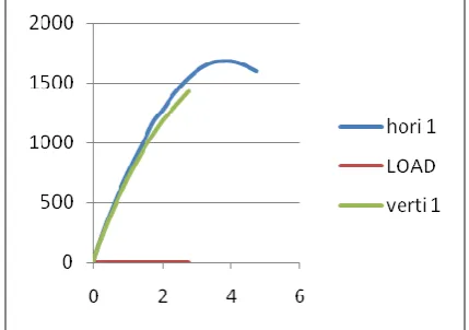
Fig.3 Load vs displacement Graph for specimens tensile oriented.
Investigations manufactured with "X" direction and "Y" direction tractable had thicknesses reliably in the 3.97 mm range contrasted with the D638 detail. A comparative impact is additionally appeared in that tests created with level elastic and vertical ductile directions had widths reliably in the 13.16-13.18 mm range contrasted with the D638 detail of 13.17 mm. The most elevated mean rigidity was found in the flat direction of elastic test, the least happened in the vertical tractable directions try as appeared in figure 4. The most astounding relative accuracy happened in level elastic direction with one standard deviation of 32.38 MPa. The most minimal happened in "Y" malleable directions at 27.5 MPa
International Journal of Innovative Technology and Exploring Engineering (IJITEE) ISSN: 2278-3075, Volume-8 Issue-9, July, 2019
[image:3.595.54.286.48.197.2]directions.
Fig. 4 Load Vs Displacement Graph of compression Oriented Specimen.
V. FINITE ELEMENT ANALYSIS
A. Introduction
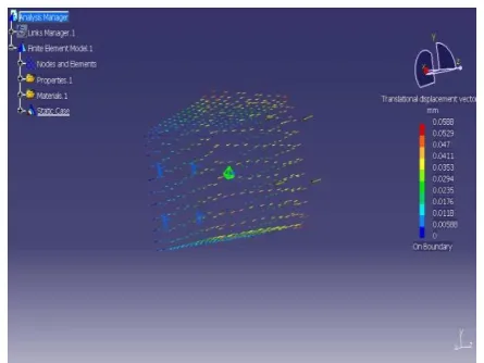
The goal of this piece of the examination was to build up a general Finite Element Analysis (FEA) model. It is to display various highlights which utilize the polymer properties of High Temperature materials [18-20]. The examination explored the high disfigurement which happens during the bowing of an element and inspected the capacity of FEA to foresee the component conduct by getting reenactment results from a model that experiences high component mutilation [21-23]. The examination incorporated the displaying of the geometry and limit conditions as appeared in figures 6-8. The material properties acquired from the pressure tests and organized work components to compute the contact powers which were contrasted with the outcomes got from the examinations as appeared Table 1.
[image:3.595.322.542.49.206.2]Fig. 5 Von misses stress for Tensile test specimen The maximum stress value is 3.88 KN/mm2.
[image:3.595.318.537.251.417.2]Fig. 6 Von misses stress for Tensile displacement test. The maximum stress value is 1.38 in/mm2
Fig. 7 Von misses stress for Compression test specimen. The maximum stress is 1.86KN/mm2.
[image:3.595.64.282.456.618.2] [image:3.595.315.538.462.629.2]Table 1. Mechanical Testing Results
EXPERIMENT Length
(mm) Width (mm) Tensile Strength (MPa) Young’s Modulus (MPa) Tensile “X” orientation
165.32 13.16 32.38 647.6
Tensile “Y”
orientation
165.28 13.18 27.52 917.3
Compression “X”
orientation
45.21 12.82 9.72 243
Compression “Y”
orientation
45.15 12.80 8.88 296
VI. CONCLUSION
The motivation behind this investigation was to dissect changeability in the mechanical properties of parts made by the Objet 3D Printing procedure because of changes in procedure parameters. A structure of tests to distinguish changes to a limited extent rigidity and malleable modulus because of changes in direction (X and Y). Future examinations will further explore the impact of part dividing on mechanical properties. The outcomes demonstrate that flat direction is having higher quality than the vertical direction.
REFERENCES
1. D Chandramohan, K Marimuthu, Bio composite materials based on bio polymers and natural fibers-contribution as bone implants, International Journal Of Advanced Medical Sciences And Applied Research, Vol No. 1, Issue No. 1, 009 – 012,2011.
2. Chandramohan, D.and Marimuthu, K., Natural fibre particle reinforced composite material for bone implant, European Journal of Scientific Research, Vol.54, No.3,384-406,2011.
3. Chandramohan, D., Marimuthu, K. Applications of natural fiber composites for replacement of orthopaedic alloys, Proceedings of the International Conference on Nanoscience, Engineering and Technology, 6167942, pp. 137-145,2011.
4. Chandramohan, D. and Marimuthu, K., “Contribution of Biomaterials to Orthopaedics as Bone Implants – A Review”, International Journal of Materials Science, Vol.5, No.3,445-463,2010
5. R.Prasannasrinivas and Chandramohan.D., “Analysis of Natural Fiber Reinforced Composite Material for the Helmet Outer shell”, International Journal of current Research, Vol.4,No.3,137-141,2012. 6. Chandramohan.D et.al., Progress of biomaterials in the field of
orthopaedics, American Journal of Applied Sciences, 11 (4),623-630,2014.
7. Sathish, T and Chandramohan, D, Teaching methods and methodologies used in laboratories, International Journal of Recent Technology and Engineering Volume 7, Issue 6, March 2019, Pages 291-293.
8. K Gurusami, K Shanmuga Sundaram, D Chandramohan, S Dinesh Kumar,P Vasantha Srinivasan & T Sathish (2019): A Comparative Study on Surface Strengthening Characterization and Residual Stresses of Dental Alloys using Laser Shock Peening, International Journal of Ambient Energy, DOI: 10.1080/01430750.2019.1614987.
9. Chandramohan, D and John Presin Kumar A. Fibre reinforced composites: A promising material for artificial limp. Data-Enabled Discovery and Applications. 1-9. 2017.
a. DOI: https://doi.org/10.1007/s41688-017-0010-1
10. Murali, B., Chandra Mohan, D. Chemical treatment on hemp/polymer composites, Journal of Chemical and Pharmaceutical Research,6(9), pp. 419-423.
12. Chandramohan, D., Bharanichandar, J, Impact test on natural fiber reinforced polymer composite materials, Carbon - Science and Technology,5(3), pp. 314-320,2013.
13. Chandramohan, D., Murali, B.. Machining of composites - A review, Academic Journal of Manufacturing Engineering,12(3), pp. 72-77,2014.
14. Pandyaraj, V., Ravi Kumar, L., Chandramohan, D. Experimental investigation of mechanical properties of GFRP reinforced with coir and flax, International Journal of Mechanical Engineering and Technology,9,. 1034-1042,2018
15. Murali, B., Chandra Mohan, D., Nagoor Vali, S.K., Muthukumarasamy, S., Mohan, A. Mechanical behavior of chemically treated jute/polymer composites, Carbon - Science and Technology,6(1), pp. 330-335. 16. Chandramohan, D and Rajesh, S. Study of machining parameters on
natural fiber particle reinforced polymer composite material, Academic Journal of Manufacturing Engineering12(3),72-77,2014. 17. Chandramohan, D et al. Mechanical, Moisture Absorption, and
Abrasion Resistance Properties of Bamboo–Jute–Glass Fiber Composites. Journal of Bio- and Tribo-Corrosion (2019) 5:66. a. DOI: https://doi.org/10.1007/s40735-019-0259-z
18. S. Dinesh kumar and K. Purushothaman (2018): Enhancement of thermal conductivity in a plate heat exchanger by using nano particles CNT, Al2O3,surfactant with De-ionised water as coolant, International Journal of Ambient Energy, DOI:10.1080/01430750.2018.1562979. 19. Chandramohan.D., and A.Senthilathiban. Effects of chemical treatment
on jute fiber reinforced composites, International Journal of Applied Chemistry, 10 (1),153-162,2014.
20. Sathish, T and Chandramohan, D, Experimental study and model development for on-line drill wear monitoring system using lab view, International Journal of Recent Technology and Engineering Volume 7, Issue 6, March 2019, Pages 281-286.
21. B.Murali and Chandramohan.D., “Fabrication of Industrial Safety Helmet by using Hybrid Composite Materials”, Journal of Middle East Applied Science and Technology, 15,584-587,2014.
22. Chandramohan, D, et.al., “Applications of CT/CAD/RPT in the Futurestic Development of Orthopaedics and Fabrication of Plate and Screw Material from Natural Fibre Particle Reinforced Composites for Humerus Bone Fixation – A Future Drift”, Malaysian Journal of Educational Technology, Vol.10,No.12,73-81,2010.
23. Chandramohan.D., “Analysis On Natural Fiber Bone Plates”, European Journal of Experimental Biology, 4(2):323-332,2014.
24. Sathish, T., and Karthick, S. “HAIWF-based fault detection and classification for industrial machine condition monitoring”, Progress in Industrial Ecology, vol. 12, no. 1-2, pp. 46-58, 2018
25. T. Sathish, and J. Jayaprakash, “Meta-Heuristic Approach to Solve Multi Period Disassembly-To-Order Problem of End-Of-Life Products using Adaptive Genetic Algorithm”, International Journal of Mechanical & Mechatronics Engineering IJMME-IJENS, Vol. 15, No. 3, pp. 59-67, 2015.
26. T. Sathish, “Experimental investigation on degradation of heat transfer properties of a black chromium-coated aluminium surface solar collector tube”, International Journal of Ambient Energy, Taylor and
Francis Publishers, Vol. 39, doi:
https://doi.org/10.1080/01430750.2018.1492456.
27. T. Sathish, “Heat Transfer Analysis of Nano-Fluid Flow in a converging Nozzle with different aspect Ratios”, Journal of New Materials for Electrochemical Systems, Vol. 20, pp. 161-167, 2017.
28. Sathish, T. “Performance measurement on extracted bio-diesel from waste plastic”, Journal of Applied Fluid Mechanics, vol. 10, pp. 41-50, 2017.
29. Sathish, T., Jayaprakash, J. “Optimizing Supply Chain in Reverse Logistics”, International Journal of Mechanical and Production Engineering Research and Development, Vol. 07, pp. 551-560, 2017. 30. Sathish, T., Periyasamy, P. “Modelling of HCHS system for optimal
E-O-L Combination section and Disassembly in Reverse Logistics”, Applied Mathematics and Information science, Vol. 13, No. 01, pp. 1-6, 2019.
31. Sathish, T., Muthulakshmanan, A. “Design and simulation of connecting rods with several test cases using AL alloys and high Tensile steel”, International Journal of Mechanical and Production Engineering Research and Development, Vol. 08,Issue 1, pp. 1119-1126, 2018. 32. Vijayan, V., Parthiban, A., Sathish, T., Siva Chandran, S., Venkatesh,
International Journal of Innovative Technology and Exploring Engineering (IJITEE) ISSN: 2278-3075, Volume-8 Issue-9, July, 2019