International Journal of Innovative Technology and Exploring Engineering (IJITEE) ISSN: 2278-3075, Volume-8 Issue-11, September 2019
3281
Published By:
Blue Eyes Intelligence Engineering & Sciences Publication
Retrieval NumberK25350981119/2019©BEIESP DOI:10.35940/ijitee.K2535.0981119
Abstract: An emerging error-detection and correcting technique developed in the recent years is Polar codes. The technique does not focus on randomization of the bits like other techniques does, but is based on the Shannon theory and channel polarization. This paper presents a successive cancellation (SC) algorithm based FPGA implementation of Polar codes. The implementation focuses on low complexity decoder for high speed applications. Software Simulation outcomes represent the execution to polar codes can outperform those are turbo or LDPC codes.
I. INTRODUCTION
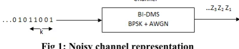
[image:1.595.57.294.371.420.2]Polar codes is used in the context of a coding problem which was traditionally formulated by Shannon back in 1948, which basically talks about transmitting information in the form of binary format with the help of noise medium. Noise medium is characterised by analytic methods like BI-DMS, BPSK+AWGN etc as shown in the figure below.
Fig 1: Noisy channel representation
Here binary bits are transmitted over the channel and noisy version of those bits is being received. Now, all that has to be done is to recover the original bits that are transmitted from noisy varieties of those digital bits 0’s and 1’s. The Shannon’s idea is to improve the performance of the system by doing something called as adding redundancy. In simple words K bits are taken and are converted to N bits, and receive the noisy versions of the N coded bits, and estimate the original message from these noisy coded bits [1]. Basically Encoding and Decoding is done here. Now, this system can perform much better than the earlier system. This is called as the coding system which can achieve the Shannon capacity only if it is done is done in a very intelligent process. This has been an open problem since many years. Many coding systems have been developed and among those wide varieties of codes the Polar Coding system can actually achieve Shannon capacity asymptotically on any given simple popular channel model. The Polar Coding system has an encoding block, a
Revised Manuscript Received on September2, 2019.
Raja Krishnamoorthy, Professor, Department of Electronics and Communication Engineering, CMR Engineering College, Kandlakoya Village, Hyderabad, Telangana, India. E-mail: [email protected]
Manivel K, Associate Professor, Department of Electronics and Communication Engineering, Mahendra Engineering, College, Namakkal, Tamilnadu, India. E-mail: [email protected]
Dr. A. Suresh Kumar, Professor, School of Computing Science and Engineering, Galgotias University Delhi NCR, India. E-mail: [email protected]
Mr. C.Vairavel, Assistant Professor, School of Computing Science and Engineering, Galgotias University, Delhi NCR, India. E-mail:
Decoding block and a construction block. The Code-construction block decides the parameters that go in encoding and decoding blocks.
Polar codes are very quickly and successfully execution outcome codes. The capacity achieving codes are nothing but the codes that approach capacity which is nothing but when these codes are used to simulate their performance seems to be very close to the capacity [2]. Unfortunately there is no proof that they achieve capacity asymptotically in mathematical terms. Therefore Polar codes are the capacity achieving codes. Later Erdal Ariksan invented codes such as Specially coupled LDPC codes and Read Mullar Codes which achieve capacity and also these codes have been proven mathematically.
The basic context that is mainly used in these polar codes is Channel Polarization. This kind of polarization is basically polarizing the given noisy channel into two extremes, which means making the channel into completely noisy or completely noiseless. This is achieved by taking N copies. Once we have N copies of the same channel, we can process them in a way that C fraction (where C represents the Shannon capacity) of the bit is completely noiseless. So, if we transmit over the channel, bits are received without any noise. The simple strategy to achieve capacity is use only those better information transmission medium and rest of medium which have to be used will be frozen.
Attractive features of these codes are
Stable, less complexity O(N log2 N) encode,
decode measurable.
Clear and straightforward implementation. Simple to design.
Advantages of these codes are:
They are easierdecode and encode algorithms.
Clear and straightforward implementation. Simple to design and straightforward higher performance.
Efficiency of hardware is high. Error free codes.
Some of the challenges that are faced are O(N) latency is huge
Shows less execution results on SCD than LPDC codes, in presence of countable N bits. Improve quality procedures are costly than LPDC, at finite N bits sample data.
FPGA Implementation of Polar Codes for Low
Complexity Decoder for High Speed
Applications
Even having these challenges, people are working on these polar codes as there is some room to improvement which is the main hope.
Arikan's [3] polarization process has been described based on elementary methods. The method described in the paper uses non stationary memory less channels which is similar to stationary ones. S. Liu. Et al [4], proposed a block fading channel based polar codes. The fading process is described as a natural polarization as the fading block changes according to the fading coefficient. G. B . Ocherer [5] presented a higher-order modulation polar codes concept presented multi-mode polar encoder and decoder with high reliability. The successive cancellation decoding algorithm was discussed by C. Condo et al [6] and S. A. Hashemi et al [7]. Minimum distance based and portioned list decoder was discussed in the literature [8].
Polar codes Parameters:
The polar code is desired with respect to three parameters namely N, K, I, where
N is mentioned to be the code length of the bits K is utilized for representing the information present in the length in bits
I is utilized for representing the bit reversed as a pair of K indices
I ⊂ {0,1,…,N-1}
The above is mentioned to be the information bit indices Bit reverse operation is nothing but simply taking n bit of integers and representing in the binary format and reverses the order into the required format takes them in the form of I
b_1,b_2,…,b_n ≜ b_n … b_2 b_1
The complementary set I^c is mentioned to be the frozen bit indices
The Kernel
The kernel is also highly utilized technique in the coding process. This is a triangular kernel. It utilizes koneke product operations as an outcome the matrix dimensions gets doubled in each iteration. Initially it begins with the 2*2 size and then goes to 4*4 size and soon.
The dimensions grow as the powers are smaller Encoding:
Encoding vector is nothing but multiplying the vector with the kernel.
The above process is quite similar to the traditional encoding process, where k message bits are multiplied directly with the generator matrix (Gu)and obtains the information which is encoded.
D is not the matrix but the value of the d is embedded inside the matrix for obtaining the efficient outcomes. In the traditional process the message gets varied with respect to the information given by the user. But in the novel encoding process the information goes efficiently without any interference of the user.
Lets observe an example of it
If rectangular matrix is taken where the rectangular matrix is embedded inside the matrix the
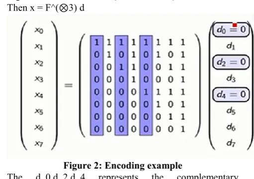
[image:2.595.308.564.286.466.2]E.g.: N = 8, K = 5, I = {1 , 3 , 5 , 6 , 7}. Then x = F^(⊗3) d
Figure 2: Encoding example
The d_0,d_2,d_4 represents the complementary information of the sets.
So due to this the developers basically use only few columns for translating the information, where the blue colored columns gets eliminated, which is quite similar to the classic form of linear encoding. It is not that much variable as compared to the traditional one. The matrix multiplication generally consists of quadratic complexity, which is not that much implementation friendly as lesser complex implementations. As the discussion is about polar codes which are asynchrotically high they need higher efficient techniques. The developers have one specific type which is necessary for
High performance computing (N log N) algorithm existing.
The equation is capable of reducing the N square order through the linear order of N log N information.
International Journal of Innovative Technology and Exploring Engineering (IJITEE) ISSN: 2278-3075, Volume-8 Issue-11, September 2019
3283
Published By:
Blue Eyes Intelligence Engineering & Sciences Publication
[image:3.595.57.293.51.230.2]Retrieval NumberK25350981119/2019©BEIESP DOI:10.35940/ijitee.K2535.0981119
Figure 3: Encoding computation tree
The above figure represents the edge or operation utilized in this technique. The x_0value block implements one kernel as an outcome one can come to observe that whatever the input that will be executed here. In the stage 0 it consists of four f values. So by cascading in an intelligent fashion several small f values can be implemented here, whose value is efficiently computable. The above figure represents the three stage outcome. So every stretched circuit can be represented with the connection, and the upper & the lower branches. The above process is named as highly efficient process. It can be utilized by applying a mat lab code with reasonable understanding of the circuit.
Any linear block code which is also very interesting for the practical implementations for several other reasons is said to be the systematic encoding of linear block codes. If one can extend the systematic codes with the polar codes then it will be very efficient. This is achieved the IEEE versions.
Systematic coding is a method of coding which is capable of representing the entire coding process as an upending process of redundancy. So in general after making the process of encoding one cannot observe the messaged bits as same as the encoded bits. Though the redundancy being added or upended, redundancy is being added in a very linear passion between the n bits that are being output, but incase the developers can sustain the messages as a copy paste as it is in the code word that is called a symmetrical code.
Decoder
Successive cancelation decoder is the most common and efficient decoder used in the industry for decoding polar codes. It’s a greedy tree search based method, where instead of searching the binary tree in an exhaustive process one foot link is selected every time and the search is carried out.
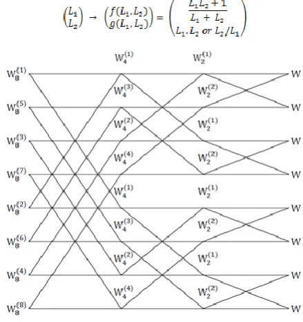
Figure 4: decoder basic structure
[image:3.595.323.543.179.413.2]It is a two way recursion based process where if two inputs L1 and L2 are given to the fundamental construction block, two variable functions are produces as outputs. Next execution based on instant bit response from top branch.
Figure 5: Recursive transformation of decoder Stage 1: Right first variable which is in Figure 5 are initialized with channel observations. For
Stage 2: in stage 2. U variable should be decoded. In case U is frozen then we treated as zero. Else, initialize ratios as likelihood basis from first right bit to side to left based on computing parameters g and f to required level L . If L >1, u calculated as 0. If L<1,u calculated as 1. If L =1,u is calculated as 1 or 0 with probability of equality
Stage 3: this stage, u going to decoded. process is like stage 2 except determine L , the value u calculated until L is determined.
Stage 4: Later, rest of U bits Decoded orderly. Previous bits are knowledgeable by present decoded bits.
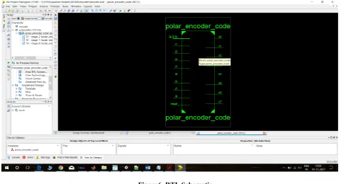
Experimental Outcomes: Polar encoder
The polar encoder described in the above section is implemented using Verilog HDL in Xilinx 14.5 edition. The
target board used is FPGA Vertex 7.
L
1f(L
1, L
2)
Figure6. RTL Schematic
International Journal of Innovative Technology and Exploring Engineering (IJITEE) ISSN: 2278-3075, Volume-8 Issue-11, September 2019
3285
Published By:
Blue Eyes Intelligence Engineering & Sciences Publication
[image:5.595.57.523.53.297.2]Retrieval NumberK25350981119/2019©BEIESP DOI:10.35940/ijitee.K2535.0981119
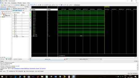
Figure 8. Simulation Results The simulation results show the encoded results of the 8
bit data. Table 1 presents utilization overview of Module of the proposed algorithm.
[image:5.595.58.540.372.736.2]Table 1: Utilisation overview of Module
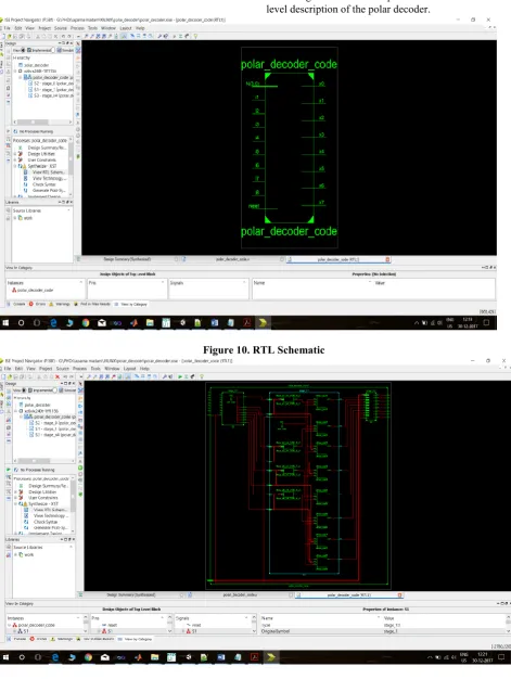
II. POLAR DECODER The figures 10 and 11 present the schematic and gate level description of the polar decoder.
[image:6.595.58.536.384.673.2]Figure 10. RTL Schematic
International Journal of Innovative Technology and Exploring Engineering (IJITEE) ISSN: 2278-3075, Volume-8 Issue-11, September 2019
3287
Published By:
Blue Eyes Intelligence Engineering & Sciences Publication
[image:7.595.57.509.51.304.2]Retrieval NumberK25350981119/2019©BEIESP DOI:10.35940/ijitee.K2535.0981119
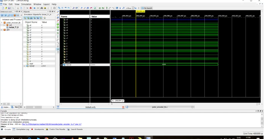
Figure 12. Simulation Results Figure 12 shows the simulation result of the decoder. The
[image:7.595.62.547.369.773.2]decoded data matches with the input data bits given to the system.
Table 2: Utilisation overview of Module
III. CONCLUSION
This paper presents a successful implementation of polar codes with successive cancellation decoding in Verilog HDL. The proposed algorithm is synthesised and tested on the Vertex 7 FPGA board. The results are all tabulated and discussed in the paper. The procedure devised consumes much less power and area compared to the traditional counterparts
REFERENCES
1. S. B. Korada, E. S¸ as¸oglu, and R. Urbanke, "Polar codes: Characterization of exponent, bounds, and constructions," IEEE Trans. Inform. Theory, vol. 56, pp. 6253-6264, 2010.
2. Tal and A. Vardy, "How to construct polar codes," submitted to IEEE Trans. Inform. Theory, available online as arXiv:1105.6164v2, 2011. 3. M. Alsan and E. Telatar, "A simple proof of polarization and
polarization for non-stationary memoryless channels," IEEE Trans. Inf. Theory, vol. 62, no. 9, pp. 4873-4878, Sept 2016.
4. S. Liu, Y. Hong, and E. Viterbo, "Polar codes for block fading channels," in IEEE Wireless Commun. and Netw. Conf. Workshops, March 2017, pp. 1-6.
5. G. B ¨ocherer, T. Prinz, P. Yuan, and F. Steiner, "Efficient polar code construction for higher-order modulation," in 2017 IEEE Wireless Commun. and Netw. Conf. Workshops (WCNCW), March 2017, pp. 1-6.
6. C. Condo, F. Ercan, and W. J. Gross, "Improved successive cancellation flip decoding of polar codes based on error distribution," in IEEE Wireless Communications and Networking Conference (WCNC), Barcelona, Spain, April 2018.
7. S. A. Hashemi, A. Balatsoukas-Stimming, P. Giard, C. Thibeault, and W. J. Gross, "Partitioned successive-cancellation list decoding of polar codes," in IEEE International Conference on Acoustics, Speech and Signal Processing (ICASSP), Shanghai, China, March 2016.
8. V. Bioglio, F. Gabry, I. Land, and J.-C. Belfiore, "Minimum-distance based construction of multi-kernel polar codes," in IEEE Global Communications Conference (GLOBECOM), Singapore, December 2017.
AUTHORS FROFILE
Dr. Raja Krishnamoorthi was born in Namakkal, Tamilnadu. He graduated in Electronics and Communication Engineering (B.E) from Anna University, Chennai, India in 2007 at degree level, Applied Electronics (M.E) as Post Graduated degree from Anna University, Coimbatore, India in 2011. He has been awarded Ph.D. degree from Anna University, Chennai, India in 2017. His main area of research activity is VLSI Physical Design, Wireless Sensor Networks and Biomedical Engineering, Cloud Computing, IoT, Digital Image Processing. He has published many research articles in refereed journals. He is currently working as Professor & Head of the Department Incharge and Dean Research and Development in the Department of Electronics and Communication Engineering at CMR Engineering College, Hyderabad, India.
Sureshkumar.A (Arumugam) was born in Salem, Tamilnadu. He Graduated in Computer Science and Engineering (B.E) from Periyar University Salem at degree level. Computer Science and Engineering (M.E) as Post Graduated from Anna University of Technology Trichy, Tamilnadu, India. He has been awarded Ph.D., for his Research work in the area of Sensor Network. He has held the position of Associate Professor and Researcher within the Centre for Computing Science and Engineering, Galgotias University, Delhi NCR, India. His main research interests are in the areas of Wireless Sensor Networks and Internet of Things (IoT). He is life member of International Association of Engineers (IAENG).
Manivel K was born in Namakkal, Tamilnadu. He Graduated in Electronics from Periyar University Salem at degree level and he received Master degree in Applied Electronics from Anna University, Tamilnadu, India, 2010. He has been awarded Ph.D., degree for his Research work in the area of image processing by Anna University, Chennai. He has held the position of Associate Professor and Researcher within the Centre for Electronics and Communication Engineering, Mahendra Engineering College (Autonomous), Tamilnadu, India. His main research interests are in the areas of image processing, artificial intelligent and embedded systems.