Int. J. Electrochem. Sci., 13 (2018) 3555 – 3565, doi: 10.20964/2018.04.60
International Journal of
ELECTROCHEMICAL
SCIENCE
www.electrochemsci.org
Short Communication
Effect of Voltage on the Microstructure and Corrosion
Properties of MAO Coatings on Biodegradable ZK60 Mg Alloys
Chenfeng Xu1,2, Xueyu Yan1, Huawei Yang1,*, Hai Yan3,*
1
Department of Stomatology, Affiliated Shanghai Tenth People’s Hospital, Tongji University, Shanghai 200072 China
2
School of Materials Science and Engineering, Jiangsu University of Science and Technology, Zhenjiang 212003 China
3
Elotouch (Suzhou) Co. Ltd., Suzhou 215009 China
*
E-mail: [email protected] (H. Yang); [email protected] (H. Yen)
Received: 10 January 2018 / Accepted: 19 February 2018 / Published: 6 March 2018
In this paper, micro-arc oxidation (MAO) is successfully used to fabricate protective coatings on biodegradable magnesium alloys. The effects of different applied voltages in the MAO process on the phase composition, coating morphology and in vitro corrosion properties of the MAO coatings are investigated by using X-ray diffraction, scanning electron microscopy, electrochemical measurements and immersion tests. The results indicate that the applied voltage has no effect on the phase composition of the coatings, while the thickness and surface morphology of the MAO coatings are significantly affected by the applied voltages in the MAO process. The electrochemical measurements and immersion tests suggest that the ZK60 alloy with the MAO coating fabricated at 350 V shows the best corrosion resistance in simulated body fluid solutions among all the investigated samples.
Keywords: biodegradable magnesium alloys; micro-arc oxidation; EIS; Tafel
1. INTRODUCTION
Micro-arc oxidation (MAO), also known as plasma electrolytic oxidation (PEO), is defined as a classical electrochemical conversion using metal or alloys as an anode to produce anodic oxide layers. As a traditional anodization method, it is commonly used to deposit ceramic coatings on Al, Ti, Mg, Ta, W, Zn, Zr, etc. [11] The greatest advantage is the tight adhesion of the porous coatings, and coatings formed by anodization are not only thicker than those formed by chemical conversion methods but also higher in strength, hardness and corrosion resistance. Phenomena such as the formation of the oxide coatings, dielectric breakdown, dissolution of pre-existing films and anodic gas evolution occur during the MAO processing. With appropriate deposition parameters, it is possible to fabricate high-quality coatings with good corrosion resistance, good wear resistance, high bonding strength and micro-hardness.
Generally, electrolyte compositions and process parameters, such as the applied voltage/current density, frequency and number of cycles are considered to have a significant influence on the resulting characteristics of the MAO coatings. Ghasemi [12] studied the effects of different electrolytes, i.e., Na2SiO3, Na3PO4 and NaAlO2, on MAO coatings on AM50 Mg alloy. Compared with the MAO
coatings obtained in the electrolytes of Na3PO4 and NaAlO2, the MAO coating obtained in the Na2SiO3
electrolyte showed better corrosion resistance due to the higher thickness and fewer open pores. Zhao [13] prepared MAO coatings on a pure Mg alloy, and the MAO coating was thick (~30 µm) and dense enough to protect the magnesium substrate from corrosion. However, if the oxidation time is too long, the dissolution of the coatings and a decrease in the corrosion resistance occur. Lv [14] investigated the effects of the treatment time on the microstructure of the MAO coatings on AZ91D alloys. It was shown that a significant change in the morphology and growth rate of the MAO coatings was observed with the increase in treatment time. The formation process of the MAO coatings normally requires various modes of DC, AC bipolar and unipolar currents [15, 16].
Although a large amount of literature on the effects of different electrolytes and process parameters has been reported [17-19], little attention has been paid to the effect of the applied voltage on the microstructure and corrosion properties of MAO coatings on biodegradable ZK60 Mg alloys. In this work, coatings with a uniform microstructure and good corrosion resistance were successfully fabricated on ZK60 magnesium alloys via an MAO process in sodium phosphate, sodium borate and potassium hydroxide-based electrolyte solutions. The phase composition and morphology of the MAO coatings formed at different applied voltages were characterized. The in vitro corrosion behaviors of the ZK60 alloys with different MAO coatings were investigated systematically by using immersion tests and electrochemical measurements.
2. EXPERIMENTAL
The electrolyte used in the MAO process was an aqueous solution composed of KOH (0.05 mol/L), Na3PO4 (0.05 mol/L) and Na2B4O7 (0.02 mol/L) (reagent grade, purchased from Sinochem
Reagent Co., Ltd., China). A graphite plate was used as the cathode. A constant applied voltage (250 V, 300 V, 350 V and 400 V) was provided by an SW172001SL 1A DC power supply (Shanghai Voltage Regulator Plant, China). The MAO process was performed at 25 °C with an MAO time of 15 minutes. The MAO-coated samples were named as 250V, 300V, 350V and 400V, respectively, based on the values of the applied voltages.
The simulated body fluid (SBF) solution used in the current investigation was prepared by dissolving reagent-grade chemicals of 0.4 g/l KCl, 8 g/l NaCl, 0.35 g/l NaHCO3, 0.06 g/l
NaH2PO4·2H2O, 0.25 g/l NaH2PO4·H2O, 0.19 g/l MgCl2, 0.19 g/l CaCl2·2H2O, 0.06 g/l MgSO4·7H2O
and 1 g/l glucose (reagent grade, purchased from Sinochem Reagent Co., Ltd., China).
The phase compositions of the samples were characterized by X-ray diffraction (DX-2700, Fangyuan, Dandong, China). The morphologies of the coating were observed using scanning electron microscopy (SEM, Quanta 200 FEG, FEI Company, Hillsboro, OR, USA). The thickness of the coatings was determined from the SEM cross-sectional images of the samples. The electrochemical polarization (Tafel) curves and electrochemical impedance spectroscopy (EIS, Nyquist plots) were recorded by using a CHI600 electrochemical workstation (CHI600, CH Instruments, Shanghai, China) with a conventional three-electrode cell in a simulated body fluid solution at the temperature of 37 ± 0.5 °C. The Tafel curves were measured with the scanning rate of 1 mV/s. The working electrode was a sample. A platinum plate was used as the counter electrode, and a saturated calomel electrode (SCE) was the reference electrode. The immersion tests were carried out in an SBF solution. The pH value of the SBF solution was adjusted to 7.4 ± 0.1 and the temperature was kept at 37 ± 0.5 °C using a water bath. The samples were immersed in 200 ml of an SBF solution for 14 days. The pH value of the SBF and the mass of the samples (after drying) were recorded every 24 h during immersion, with a blank SBF solution as the control.
3. RESULTS AND DISCUSSION 3.1 XRD analysis
[image:3.596.184.411.550.713.2]
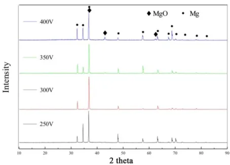
Fig. 1 shows the XRD patterns of the ZK60 alloys with MAO coatings fabricated at different applied voltages. Only the peaks originating from the MgO phase and Mg substrate can be indexed in all the XRD patterns, and the peak intensity of the MgO phase increases with the increasing applied voltages. These are consistent with previous studies reported by Liang [20] and Lee [21]. In the phosphate electrolyte solution, the main reactions of the formation of the MAO coatings are listed as follows:
Mg→Mg2+
+2e- (1) Mg2++2OH-→Mg(OH)2 (2)
Mg(OH)2→MgO+H2O (3)
In the anode reaction, accompanying the dissolution of the magnesium alloy substrate, Mg2+ ions are released, and then the Mg(OH)2 is formed along with OH- ions in the solution. In the final
stage, the formed Mg(OH)2 is transformed to the MgO phase due to the discharge at high voltages and
high temperatures. During the reactions, the B4O72- ions rapidly decomposed into oxygen, which
promoted the formation of the oxide film on the surface of the magnesium alloy substrate under the effects of electric fields.
3.2. SEM morphologies
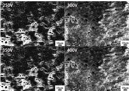
Figure 2. SEM morphologies of MAO coatings prepared at different applied voltages: 250 V; 300 V; 350 V; 400 V
[image:4.596.84.508.377.675.2]
coatings is composed of a tiny, “volcano”-like molten materials. There are many well separated and uniformly distributed micro-sized pores on the surface of the MAO-treated ZK60 alloys. The porous surface over the whole samples could originate due to the high temperature in the micro-arc discharge channels during the micro-arc oxidation process. [22] This phenomenon occurred due to discharge sparking on the surface of the substrates at weak locations; the gas bubbled out from the discharge channels, and subsequently, molten magnesium oxide solidified quickly around it. [23, 24]
The porous surface of the MAO-treated ZK60 alloys is beneficial for the cell attachment, propagation and anchorage of the implant when it is implanted in a human body. As shown in Fig. 2(a), the MAO coating fabricated at 250 V possesses a relatively non-uniform distribution of pores with a low porosity and a large pore size distribution (approximately 0.65~3.75 μm), and there are many molten particles on the surface. During the MAO process, a low applied voltage (250 V) means a relatively small current density, resulting in a low discharge intensity and, consequently, a low porosity.
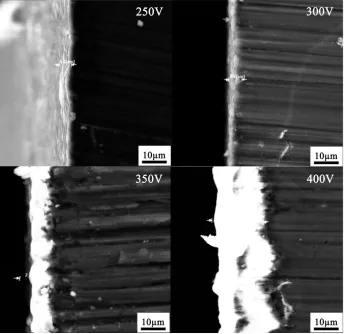
Figure 3. Cross-sectional SEM images of the coatings prepared by micro-arc oxidation on ZK60 alloys at different applied voltages: 250 V; 300 V; 350 V; 400 V
[image:5.596.127.471.289.623.2]
coating surface. During the MAO process, the main growth of the MAO coating occurs in the uniform micro-arc oxidation stage and especially in the current steady stage. When the voltage is low, the input energy and current is small and the damage of the ceramic film in the breakdown process is less; thus, the ceramic film is relatively dense, and the porosity is low. When the voltage is increased, the steady current value becomes larger. With a larger discharge energy during the reaction, more heat is generated instantaneously, which leads to the generation of more oxygen and molten products. As a result, the size of the discharge pores is enlarged, and more molten materials are deposited on the surface. To some degree, the coating could not be optimized but peeled off and was coarse when the applied voltage exceeded a critical value. [25] It was also demonstrated that fierce sparking arcs occurred at a high voltage in the electrolyte, which caused negative effects such as thermal cracking in the coatings. [26]
[image:6.596.158.439.323.539.2]These results suggest that the applied voltage has a significant effect on the surface morphologies of the MAO coatings on ZK60 alloys, especially for the size and distribution of the micropores using the present electrolyte.
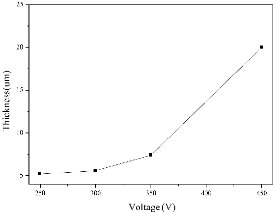
Figure 4. The relationship of the MAO coating thickness as a function of the applied voltages used in the MAO process
demonstrated that the growth rate of the MAO coatings is accelerated under higher anodizing voltages [27, 28], and the higher voltage increases the amount of the ejected molten oxides, which induces serious packing behaviors of the oxides and results in a greater surface roughness of the coatings [29]. Therefore, the high applied voltage will promote the electrochemical reactions in the MAO process; the thickness of the MAO coatings will increase, and more defects will be generated in the coatings.
3.3 Electrochemical measurements
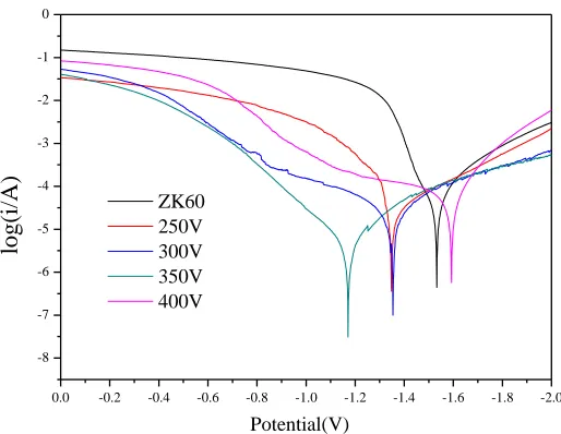
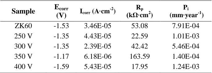
Fig. 5 shows the electrochemical polarization curves of ZK60 alloys with different MAO coatings and without coatings measured in SBF solutions at 37 ± 0.5 °C. The electrochemical parameters, such as the corrosion current density (Icorr), corrosion potential (Ecorr), polarization
resistance (Rp) and corrosion rate (Pi), are calculated from the obtained polarization curves by using a
Tafel fitting, and they are listed in Table 1. As seen from Table 1, the MAO coatings on the ZK60 alloy can improve the corrosion potential of the uncoated ZK60 alloy up to -1.17 V and decrease the corrosion current density by an order of magnitude. The increased corrosion potential and decreased corrosion current density in the MAO-coated ZK60 alloys indicates better corrosion resistance than the uncoated ZK60 alloy. It can be clearly observed from Table 1 that the ZK60 alloy sample with an MAO coating at an applied voltage of 350 V possesses the best corrosion resistance with the largest polarization resistance of 163.59 kΩ·cm2 and the lowest corrosion rate of 1.4×10⁻⁴ mm·year-1 in all the investigated samples.
Figure 5. Electrochemical polarization curves of ZK60 alloys with different MAO coatings and without coatings measured in SBF solutions at 37 ± 0.5 °C
The corrosion resistance of the MAO coatings is mainly determined by the thickness, microstructure, surface defects and phase compositions of the coatings. As shown in Fig. 1, the phase
0.0 -0.2 -0.4 -0.6 -0.8 -1.0 -1.2 -1.4 -1.6 -1.8 -2.0 -8
-7 -6 -5 -4 -3 -2 -1 0
Potential(V)
log(i/
A) ZK60
[image:7.596.171.428.458.657.2]
composition of the MAO coatings fabricated at different applied voltages is only the MgO phase and does not change with the applied voltages. Therefore, the corrosion resistance of the MAO coatings is mainly affected by the other three factors. For example, the MAO coating fabricated at 250 V shows the worst corrosion resistance among all the studied samples because of its lowest thickness. The effect of corrosion protection is found to be proportional to the thickness of the coatings. A thick coating is beneficial for the improvement of the corrosion resistance. In addition, the integrity of the MAO coatings also greatly affects the corrosion resistance. For instance, the MAO coating fabricated at 400 V shows the worst corrosion resistance among all the coated samples despite having a greater thickness. This is probably due to the presence of large micropores and cracks in the coatings, which allows more corrosive media to penetrate the coating, thus deteriorating its corrosion resistance. [30] As indicated in the SEM morphology images of all four MAO coatings, the coating fabricated at an applied voltage of 350 V has the smallest pore size, a relatively low porosity, fewer cracks and a relatively high thickness, leading to a high corrosion resistance of the coating.
Table 1. Electrochemical parameters calculated from the polarization curves of the ZK60 samples coated with different MAO coatings
Sample Ecorr
(V) Icorr (A·cm -2
) Rp
(kΩ·cm2)
Pi
(mm·year-1)
ZK60 -1.53 3.46E-05 53.08 7.91E-04
250 V -1.35 4.43E-05 22.59 1.01E-03
300 V -1.35 2.39E-05 42.42 5.46E-04
350 V -1.17 6.18E-06 163.59 1.40E-04
400 V -1.59 5.43E-05 17.95 1.24E-03
[image:8.596.127.470.360.479.2]
Figure 6. Nyquist plots of the ZK60 alloys with different MAO coatings and without coatings measured in SBF solutions at 37 ± 0.5 °C
3.4 Immersion tests
Figure 7. Changes of solution pH (left) and sample mass (right) as a function of immersion time for the ZK60 alloys with different MAO coatings and without coatings measured in SBF at 37 ± 0.5 oC
To further investigate the in vitro corrosion behaviors of the studied Mg alloys, immersion tests were carried out in SBF solutions at 37 ± 0.5 °C for a duration of 20 days. The changes in the solution pH and sample mass as a function of the immersion time are plotted in Fig. 7. The solution pH of the uncoated ZK60 alloy increased rapidly to 9.7 after 2 days of immersion and then became stable and remained constant at approximately 10.2; meanwhile, the mass of the uncoated sample decreased continuously with increasing immersion time. The magnesium alloys immersed directly in the SBF solution quickly react with the solution and release a large amount of Mg2+, resulting in an increase in the OH- concentration in the solution and leading to a sharp rise in the solution pH. Then, Mg(OH)2
crystals are gradually deposited on the sample substrate, and at the same time, calcium phosphate will be slowly deposited on the surface of the sample. Finally, the solution system will reach a balance
0 2 4 6 8 10 12 14 16
7.5 8.0 8.5 9.0 9.5 10.0 10.5
pH
Days
ZK60 250V 300V 350V 400V
0 2 4 6 8 10 12 14 16
3.5 4.0 4.5 5.0 5.5 6.0 6.5 7.0
ZK60 250V 300V 350V 400V
Ma
ss(g)
[image:9.596.187.408.74.232.2] [image:9.596.64.539.326.508.2]
where the OH- concentration becomes stable, and the pH is unchanged. For the samples with MAO coatings, the solution pH increased to 9.2 after 2 days of immersion and then became stable, while the mass of the samples did not obviously change. During the immersion tests, the SBF solution infiltrated to the pores on the surface of the micro-arc oxidation sample, resulting in the reaction of Cl- in the SBF solution directly with the inner layer of magnesium oxide to form free Mg2+. With the increase in the Mg2+ concentration in the solution, the concentration of OH- in the solution increases, and magnesium hydroxide that is generated in the reaction deposits in the pores of MAO coatings, thus hindering the corrosion of the samples by the SBF solution. Further, the biomimetic deposition of calcium phosphate also covers the sample surface and protects the sample from corrosion during the immersion process.[31] The deposition of magnesium hydroxide and biomimetic calcium phosphate leads to the low pH value of the SBF solution and the unchanged mass for the samples with MAO coatings. Compared with the uncoated ZK60 alloy, the ZK60 alloys with MAO coatings have significantly improved corrosion resistance in the SBF solution. This is in accordance with the results obtained from the electrochemical measurements.
4. CONCLUSIONS
In summary, MAO coatings are successfully fabricated on a biodegradable ZK60 Mg alloy. The MAO coatings are composed of the single phase MgO, and the applied voltage has no effect on the phase composition of the coatings. The thickness and the surface morphology of the MAO coatings are significantly affected by the applied voltage in the MAO process. The electrochemical measurements and immersion tests indicate that the ZK60 alloy with the MAO coating fabricated at 350 V shows the best corrosion resistance in the SBF solution among all the investigated samples. The good in vitro corrosion resistance of the ZK60 alloy with the MAO coating fabricated at 350 V is mainly attributed to the relatively homogeneous surface microstructure with few defects.
ACKNOWLEDGMENTS
The present work was supported by National Natural Science Foundation of China (Grant No. 51471120) and the Fundamental Research Funds for the Central Universities (No.22120170200).
References
1. Q. Chen, G. A. Thouas, Mater. Sci. Eng. R: Reports, 87 (2015) 1.
2. X. Wang, S. Xu, S. Zhou, W. Xu, M. Leary, P. Choong, M. Qian, M. Brandt, Y. Xie, Biomaterials, 83 (2016) 127.
3. K. Xia, H. Pan, T. Wang, S. Ma, J. Niu, Z. Xiang, Y. Song, H. Yang, X. Tang, W. Lu, Mater. Sci. Eng. C, 72 (2017) 676.
4. H. Yang, K. Xia, T. Wang, J. Niu, Y. Song, Z. Xiong, K. Zheng, S. Wei, W. Lu, J. Alloys Compd., 672 (2016) 366.
6. K. Li, B. Wang, B. Yan, W. Lu, J. Biomater. Appl., 28 (2013) 375.
7. B. Wang, P. Huang, C. Ou, K. Li, B. Yan, W. Lu, Int. J. Mol. Sci., 14 (2013) 23614.
8. K.K. Li, B. Wang, B. Yan, W. Lu, Chin. Sci. Bull., 57 (2012) 2319.
9. C. Ou, W. Lu, Z. Zhan, P. Huang, P. Yan, B. Yan, M. Chen, Int. J. Electrochem. Sci., 8 (2013) 9518.
10. W. Lu, C. Ou, Z. Zhan, P. Huang, B. Yan, M. Chen, Int. J. Electrochem. Sci., 8 (2013) 10746. 11. L. R. Krishna, G. Sundararajan, JOM, 66 (2014) 1045.
12. A. Ghasemi, V. S. Raja, C. Blawert, W. Dietzel, K. U. Kainer, Surf. Coat. Technol., 204 (2010) 1469.
13. L. Zhao, C. Cui, Q. Wang, S. Bu, Corr. Sci., 52 (2010) 2228.
14. G. H. Lv, H. Chen, L. Li, E. W. Niu, H. Pang, B. Zou, S. Z. Yang, Curr. Appl. Phys., 9 (2009) 126. 15. S.V. Gnedenkov, O.A. Khrisanfova, A.G. Zavidnaya, S.L. Sinebryukhov, V.S. Egorkin, M.V.Nistrat
ova, A. Yerokhin, A. Matthews. Surf. Coat. Technol., 204 (2010) 2316. 16. Y. Gao, A. Yerokhin, A. Matthews, Appl. Surf. Sci., 316 (2014) 558.
17. J. Dou, Y. Chen, Y. Chi, H. Li, G. Gu, C. Chen, Phys. Chem. Chem. Phys., 19 (2017) 15110.
18. E. Erfanifar, M. Aliofkhazraei, H. F. Nabavi, A. S. Rouhaghdam, Surf. Coat. Technol., 315 (2017) 567.
19. Z. U. Rehman, S. H. Shin, H. T. Lim, B. H. Koo, Surf. Coat. Technol., 311 (2017) 383 20. J. Liang, P. Bala Srinivasan, C. Blawert, W. Dietzel, Corros. Sci., 51 (2009)2483. 21. K.M. Lee, Y.G. Ko, D.H. Shin, J. Alloys Compd., 615 (2014) S418.
22. F. Liu, J. Xu, F. Wang, L. Zhao, T. Shimizu. Surf. Coat. Technol., 204 (2010) 3294. 23. J.J. Zhuang, R.G. Song, N. Xiang, Y. Xiong, Q. Hu, Surf. Eng., 33 (2017) 744.
24. N. Xiang, R.G. Song, H. Li, C. Wang, Q.Z. Mao, and Y. Xiong, J. Mater. Eng. Perform., 24 (2015) 5022.
25. J. P. Lu, G. P. Cao, G. F. Quan, C. Wang, J. J. Zhuang, R. G. Song, J. Mater. Eng. Perform., 27 (2018) 147.
26. X.Z. Jiang, S. Lu, L. Tang, Z.X. Wang, and J. Chen, Key Eng. Mater., 575 (2014) 472. 27. R.O. Hussein, D.O. Northwood, X. Nie, Surf. Coat. Technol., 237 (2013) 357.
28. X. Lin, L.L. Tan, Q. Zhang, K. Yang, Z.Q. Hu, J.H. Qiu, Y. Cai, Acta Biomater., 9 (2013) 8631. 29. Hui Tang, Yu Han, Tao Wu, Wei Tao, Xian Jian, Yunfeng Wu, Fangjun Xu, Appl. Surf. Sci., 400
(2017) 391.
30. Y. Yu, S. Kuang. J. Li, JOM, 67 (2015) 2133.
31. W. Lu, Z. Chen, P. Huang, B. Yan, Int. J. Electrochem. Sci., 7 (2012) 12668.