This is a repository copy of
CSP methods for identifying atomic actions in the design of
fault tolerant concurrent systems
.
White Rose Research Online URL for this paper:
http://eprints.whiterose.ac.uk/971/
Article:
Tyrrell, A.M. orcid.org/0000-0002-8533-2404 and Carpenter, G.F. (1995) CSP methods for
identifying atomic actions in the design of fault tolerant concurrent systems. IEEE
Transactions on Software Engineering. pp. 629-639. ISSN 0098-5589
https://doi.org/10.1109/32.392983
[email protected]
https://eprints.whiterose.ac.uk/
Reuse
Items deposited in White Rose Research Online are protected by copyright, with all rights reserved unless
indicated otherwise. They may be downloaded and/or printed for private study, or other acts as permitted by
national copyright laws. The publisher or other rights holders may allow further reproduction and re-use of
the full text version. This is indicated by the licence information on the White Rose Research Online record
for the item.
Takedown
If you consider content in White Rose Research Online to be in breach of UK law, please notify us by
IEEE TRANSACTIONS ON SOFTWARE ENGINEERING, VOL. 21, NO. 7, JULY 1995 629
CSP Methods
for
IdentiQing Atomic Actions
in the Design of Fault Tolerant Concurrent Systems
Andrew M. Tyrrell, Member,
IEEE, and Geof F. Carpenter
Abstract-Limiting the extent of error propagation when faults occur and localizing the subsequent error recovery are common concerns in the design of fault tolerant parallel processing sys- tems. Both activities are made easier if the designer associates fault tolerance mechanisms with the underlying atomic actions of the system. With this in mind, this paper has investigated two methods for the identification of atomic actions in parallel proc- essing systems described using CSP. Explicit trace evaluation forms the hasis of the first algorithm, which enables a designer to analyze interprocess communications and thereby locate atomic action boundaries in a hierarchical fashion. The second method takes CSP descriptions of the parallel processes and uses struc- tural arguments to infer the atomic action boundaries. This method avoids the difficulties involved with producing full trace sets, but does incur the penalty of a more complex algorithm.
Index Term-Atomic actions, concurrent systems, CSP, fault tolerance.
I. INTRODUCTION
DISTRIBUTED processing system, comprising a set of dis-
A
crete processing units, offers the user not only the pros- pect of increased efficiency and throughput through parallel- ism, but its inherent redundancy might also be exploited to enhance reliability. To do so requires a properly designed faulttolerance infrastructure which maintains the integrity of the system under fault conditions. This paper describes CSP-based methods which facilitate the placement of fault tolerance soft- ware structures across a distributed system to ensure safe op- erations in the presence of faults.
Notwithstanding the use of standards and guidelines [l], [2], [3] in the design of software-based real-time systems for
safety-critical applications, and the concomitant adoption of formal methods, it is probable that faults will still be intro- duced into a design either explicitly as part of a particular component or implicitly through the omission of a particular feature. It is unrealistic to expect all software design faults to be detected during design and testing, and latent faults may persist into system use [4].
Fault tolerance [5] is often incorporated into a design as a ruggedization process to protect a process or set of processes regarded as critical to safe system operation. The fault toler- ance mechanisms are required to recognize faults by the errors they cause and to prevent error migration from the faulty proc-
Manuscript received June 1993; revised August 1994.
A.M. Tyrrell is with the Department of Electronics, University of York, Heslington, York, YO1 5DD, UK; e-mail: [email protected].
G.F. Carpenter is with the Department of Electrical and Electronic Engi- neering and Applied Physics, Aston University, Aston Triangle, Birmingham, 8 4 7ET, UK.
IEEECS Log Number S95020.
ess to elsewhere in the system, so that error recovery is local-
ized. The extent of the error recovery operation can be limited if a boundary can be identified within the state-space of the distributed system across which error propagation by inter- process communication is impossible; it must include all proc- esses which interact with the function being protected and ex- clude all processes that do not interact with it. In other words, the state-space of the system has to be partitioned into a hier- archy of atomic actions [6]. It is then possible to introduce a
distributed error detection and recovery mechanism around the atomic action [7] which ensures that all the processes affected
by the fault cooperate in recovery. This localization of fault tolerance simplifies the design and can help to meet timing constraints in real-time systems [8].
Methods for determining hierarchical sets of atomic actions are not widely known. This paper describes methods which use the mathematically based notation of Communicating Sequen- tial Processes (CSP) [9] to describe the operation of a distrib- uted system, and the interactions between the processes. The analysis allows the designer to identify hierarchical sets of atomic actions within the design. The model of the system can then be used to place fault tolerance software structures, cor- rectly including all participants.
II.
ATOMIC ACTIONS AND FAULT-TOLERANCETo an external observer the activity of a process is defined by its sequence of external interactions; any internal actions (of which there may be many) can not affect the extemal ob- server, at least until the next extemal interaction. This allows the concept of an atomic action to be derived [6]: the activity
of a set of processes is defined as an atomic action if there are no interactions between that set of processes and the rest of the system for the duration of that activity. The extension to hier- archically nested atomic actions is straightforward. These con- cepts are well-known in distributed transaction processing [lo]
from which field many other attributes of atomic actions, such as serializability, failure atomicity and permanence of effect can be defined.
The process of identifying the atomic actions within a parallel system design brings into clear focus the structure of interproc- ess interactions and thus the route by which errors might propa- gate under fault conditions. All common mechanisms for provid- ing fault tolerance in parallel systems, such as forward error re- covery [ll], N-version programming [12], conversations [ l l ] ,
consensus recovery blocks [ 131 and distributed recovery blocks [14], have to cope with error confinement and achieve this by
imposing logic structures “around” atomic actions [ 151.
630 IEEE TRANSACTIONS ON SOFTWARE ENGINEERING, VOL. 21, NO. 7, JULY 1995
A generalized fault tolerant mechanism could be considered
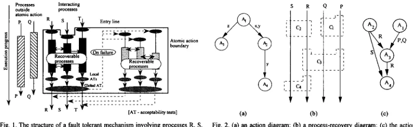
as a coordinated set of recoverable blocks, with one recoverable block in each interacting process, allowing distributed error de- tection and recovery. The mechanism is bounded by an entry line, an exit line and two side walls which completely enclose the set of interacting processes which are party to the mecha- nism, and across which interprocess interactions are prohibited. The structure is indicated diagramatically in Fig. 1.
The enhy line defmes the start of the atomic action and con- sists of a coordinated set of recovery points for the participating processes. The exit line comprises a coordinated set of accept- ability tests. Only if all participating processes pass their respec- tive acceptability tests is the mechanism deemed successful and all processes exit, in synchronism, from the action. If any ac- ceptability test is failed, recovery is initiated and processing “passed” to another set of recoverable processes. Thus all proc- esses in the atomic action cooperate in error detection.
The duality of atomic actions and recovery mechanisms has been discussed at length in [lo]. Atomic actions can be viewed as modeling an “object-action’’ type of system where atomic actions operate on objects. Expressed graphically as an action diagram (Fig. 2) circles represent actions, and arcs show the dependencies between actions. Thus, in Fig. 2, action A2 uses objects “x” and “y” released by action Al. Similarly, action Ad uses “y” when it has been released by action A2. A comparison with Fig. 1 shows that the recovery mechanism is the dual of the action and the process is the dual of the object; a mecha- nism Ci is replaced by action Ai with an arc connecting Ai with Aj if Ci and C, have processes in common. Thus, Fig. 2b and Fig. 2c can be regarded as duals. In the context of this paper, for example, action A3 provides a fault tolerant function op- erating on processes P, Q, and R.
Any attempt to incorporate an entry line and an exit line at arbitrary locations in a concurrent system is unlikely to lead to a properly formed recovery mechanism. It is necessary to identify a boundary within the state space of the complete set of processes across which error propagation by communication is prevented. Clearly, this boundary will be the boundary of an atomic action, since such a boundary of necessiQ prohibits the passing of information to any process not involved in the atomic action and similarly embraces all interacting processes within the atomic action. Recovery mechanisms can be nested
Atomic action boundary
J. +*--&I I I I I : I I II I I : 1 - -
-:
[AT - acceptability tests] R S TFig. 1 . The structure of a fault tolerant mechanism involving processes R, S, and T.
systematically in the same hierarchical fashion as atomic ac- tions. If this duality is not imposed, then should the system attempt to backtrack and recover in response to a fault, pro- gressive collapse by the domino effect [ 1 I] can occur.
In the literature, strategies for implementing fault tolerance in parallel systems [16], [17], [18], [19] and for handling problems which occur if the chosen mechanism is incorrectly located, have received more detailed attention than the funda- mental problem of placing the mechanisms correctly. Correctly placed mechanisms, coincident with atomic action boundaries, avoid error propagation problems. This paper is concemed with the analysis of a prototype design for atomic actions. Ideally, a design method would incorporate the requisite, ap- propriately placed, atomic actions and the associated fault tol- erance infrastructure into a system with a minimal amount of reanalysis and redesign, and an eventual goal is to define such a design method. However, the techniques are still insufi- ciently mature for this to be achieved and consequently this paper retains the normal design practice in which fault toler- ance mechanisms are superimposed upon selected atomic ac- tions and the new designs subjected to reanalysis.
111. STATE SPACE METHODS FOR IDENTIFYING
ATOMIC ACTIONS
Substantial work has been performed on the ability to model systems, and to reason about their behavior, using state space representations such as Petri nets or GMB [20], [21]. In the
Petri net approach, each process state can be associated with a Petri net place, and each state transition with a Petri net transi- tion [22]. Process execution is simulated by allowing marking tokens to flow through the Petri net. From the formulation of a reachability graph, the behavior of the Petri net, and therefore of the modeled system, can be analyzed.
Experience with occam [23] as a design language for loosely-coupled real-time concurrent systems [24], [25] has led to Petri net methods for identifying atomic actions. By only permitting synchronous, atomic, communications, occam forces communicating processes into mutual synchronization at communication points. This not only imposes a strict dis- cipline on the designer (because errors in the synchronization logic can lead to deadlock) but also leads to a system more
J‘
(3
S R o P
(a) (b) (C)
[image:3.614.105.516.534.661.2]TYRRELL AND CARPENTER CSP METHODS FOR IDENTIFYING ATOMIC ACTIONS IN THE DESIGN OF FAULT TOLERANT CONCURRENT SYSTEMS 63 I
amenable to analysis. The system is designed using the re- quirement specification and modeled as a Petri net. Examina- tion of the state reachability graph permits the designer to identify the boundaries of atomic actions. Inspection deter- mines which atomic action boundary encloses which system function, and an appropriate error detection and recovery mechanism to protect any chosen system function can then be incorporated at the level of the atomic action without disturb- ing the constituent processes or their interprocess actions.
Although the method is effective, it requires:
1) translation of an existing textual Occam design into a
2) translation between the graphical Petri net and set theory
3) translation of the identified atomic action entry and exit
which are made more difficult because:
4) for all but the simplest examples, there is a computational
Although automated tools exist for these translation proc- esses, often error-prone manual methods are still involved. For Petri-net-based methods the designer must be satisfied that the translation steps 1-3 do not themselves introduce errors.
Occam has a mathematical basis in the theory of Communi- cating Sequential Processes (CSP) [9]. CSP permits a funda- mental description of a concurrent processing system in terms of the component processes, the interactions between the proc- esses, and interactions with the real-world environment. Since a CSP description is directly amenable to mathematical analy- sis, it is possible to decide behavioral properties, such as the presence of reachability pathologies, without the need for er- ror-prone translation into a complementary representation. The ability to reason about timeliness in recent extensions to CSP
[26] should further promote its use in the design of time-
critical and safety critical systems.
The trace of a CSP process is a record of the sequence of events in which a process could engage and indicates directly a possible execution behavior of that process [27]. During the
design phase it would be advantageous to determine all the possible traces which a process might produce. This procedure is termed trace evaluation in this paper. For any but the sim- plest process there will be a number of possible traces; for a set of concurrently executing processes the overall trace set will be all permitted interleavings of the traces of the compo- nent processes. If the processes interact only by synchronous communications, then the processes are brought into synchro- nism for the communication event. The communication event will be in the alphabet of both the communicating processes and will constrain the set of all possible traces.
It is not practicable to create the complete set of traces un- less the set of processes is subject to certain constraints:
1) The processes must terminate, or arrive at a previously reached state, in a finite number of steps, else the set of traces becomes infinite.
2) Where program flow is made dependent on the value of variable expressions, static analysis has to consider all
graphical Petri net;
or matrix-based methods for reachability analysis;
points back to the original Occam design;
explosion which could restrict the analysis.
possible values within the range of the variable expres- sion, which may be infinite and lead to an infmite set of traces.
3) No. 2) precludes from analysis classes of loops where trace evaluation would have to evaluate loop guards, and also the use of subscripted communication channels where the subscript is determined by a variable expression.
4)Guarded choice (and thus nondeterminism) can be in- cluded provided the truth value of the guard is reflected in the trace set.
5) Interprocess communications occurring in loop con- structs pose major problems for trace evaluation; in par- ticularly if the loop iteration is controlled by a variable expression which is even indirectly determined by the real-world environment, then analysis can only be per- formed for special cases, i.e., where a subset of these environmental values are considered.
6)Certain commonly occurring forms of loop can be handled; for example, if the loop is executed a prede- fined number of times (e.g., the conventional FOR loop) and the number of communications in both processes exactly match, or if both communicating processes have matched loops which iterate synchronously in both processes (as in the real world robot example).
Trace evaluation can be tedious and error-prone if per- formed manually, but it may be readily automated. An auto- mated tool, termed CoPla, has been built at the University of York within an X-Windows environment [28].
Iv.
CSP AND ATOMIC ACTION IDENTIFICATIONTrace analysis can be used to identify atomic actions within a CSP design and to infer a hierarchical arrangement of these atomic actions. The technique presented here is inspired by the successful Petri net methods [29]; it requires the designer to evaluate all the possible execution traces for the CSP design and then to analyze process execution for events which are interprocess communications. By definition, the activity of a set of processes constituting an atomic action is such that no interactions take place between that set of processes and the rest of the system. Consequently the boundary of the atomic action can then be used for the proper incorporation of coordi- nated error detection and error recovery mechanisms within CSP designs.
Conventionally the complete set of possible traces for a process, P, is designated by
where
traces(P) = {tl, tz,
...,
tk}t, = <e,,, e,Z,
...,
e,,,...,
J>
and the event e,, corresponds to the jth event in the ith possible trace t,. J is the successful termination event. (Strictly speak- ing, <e,l>, <e,l, e , p , and all intermediary event sequences are also members of traces(P) as well as <e,l, e,*,
...,
e,,, ...,,/
>; this paper only consider tracesThe algorithm for trace evaluation is a straightforward ap- plication of continuous simplification. Given P, all the events
632 IEEE TRANSACTIONS ON SOFTWARE ENGINEERING, VOL. 21. NO. 7, JULY 1995
eil which can be the first element of the trace are extracted, to yield a simpler process P/eil (P after engaging in eil ), thus:
traces(P) = traces(e,, A (P / ell))Utraces(ezl A(P / ez,))u .
. .
=Utraces(eil A ( P / ~ ~ ~ ) )i=l
where A is the catenation operator. The function
traces(eil A (P/ei2)) can then be evaluated in a similar fashion.
Consider N processes in concurrent execution:
F = PI
11 ... 11
pn11
...
11
PN As before, for each component process, P,:where
traces(P,) = {ti, tz,
...,
tklt i = c e:,,ei,
...,
e:,. .
.,
J" >Note, a superscript character is added to show that e{ and
J'" occur within process
P,
.
Each event may be further cate-gorized, either as being local to its constituent process (thus, I:, appearing only in the alphabet of process,
Pn)
or as being acommunication event (thus, c:"
,
appearing in the alphabets of both processes P., P,, which participate in the communication, and thereby forcing synchronization). For each process P,, the local events 1: form the set L, and the communication eventsc: form the set C.; thus:
.(P,)=
L,
uc,
1: E L "
c: EC,
The traces of the set of processes Pwill be all permitted inter- leavings of the traces of the component processes, Written as:
where
traces(23) = {tl, t2,
..., k)
t i = < g 11, g 12,
...,
gij, ...) J'
Here, the event g,, corresponds to the jth event in the ith possible trace ti of traces(23). This general event gij is either an element from the alphabet of one of the constituent processes if it is a local event; otherwise it must appear in the alphabet of exactly two processes as a communication event. Thus:
3n: g, E a(PJ
(g,, E L,Jv(gi, E C,Agi, E C,A n+m>
The method for identifying hierarchically nested atomic ac- tions is defined in algorithms 1 and 2. Algorithm 1 defines how the entry and exit lines to the atomic action are identified.
A. Algorithm 1
obvious extension to more than three processes):
Given three processes P,, P,, P, in parallel execution (with
1) Add before the start of each process the special events: ; recall that the last event in each e:, , e:,il, and
process is followed by Jp,
,P,
and f, respectively.2) Select a sequence of consecutive events e,9 -5
. . .
-
> e$ -5. . .
-> e:.within P, which are to be constituents of the atomic ac- tion. The sequence must enclose fully any parallel or se- lection constructs within the sequence. Note that e$i, and JP will not be part of this sequence.
3) Defme the empty sets S, F, K, J.
S := {}; F := {}; K := {}; J := { }
4) Generate traces(F), (including e$$ and Jp).
5 ) For each trace t, in traces(?), locate gi, = er,
.
Add gi(m.l) to set S.(t/tl)l (tl E traces(F))
(vgim
1)
(gim E t l ) ~ (gim =G)
+ gi(m-1)6) For each trace ti in traces(lp), locate gin =e:,,
.
Add gi(n+l) to set F.(tl E tJaces(F))
(vgin)l(gin ~ t l ) ~ ( g i n
=a)
-j F:=FUgi(n+I)7) Compute the set difference K = S-F. This defines the complete set of events which must immediately precede the start of the atomic action.
8) Compute the set difference J = F-S. This defines the complete set of events which must immediately follow the end of the atomic action.
B. Justification of Algorithm 1
Initially, before algorithm 1 is executed:
K = O ,
J = O .
S = O ,
F = OThe sequence of events in P, which are to be constituents of the atomic action are described as:
e,9 ->
. . .
-
> e$ ->. .
.
-> e:,,If all e; E L, then no interprocess communications occur.
Since the trace evaluation determines all possible traces, the sets S and F will both contain all possible events (in other processes) which may interleave with the events e:, ->
. . .
-> e:,, and de- termining the set difference will eliminate all these events. As expected, the atomic action is local to process P,.If any e$ E C, then interprocess communications do occur
and will synchronize both parties to the communication (since e$ E C, or e$ E C, , as well as C,). Suppose the communica-
TYRRELL AND CARPENTER CSP METHODS FOR IDENTIFYING ATOMIC ACTIONS IN THE DESIGN OF FAULT TOLERANT CONCURRENT SYSTEMS 633
fects they have in the trace evaluation and are constrained to be intemal to the atomic action. It is argued above that the sets K and J contain the events which must precede and which must follow the atomic action and identifying the host process for process P, (equivalently Pr) which can immediately follow the last communication with P, but cannot contain any event which must precede it. Consequently, the set difference operations to give K and J will identify the events in other processes which form the entry line to and the exit line from the atomic action. (Note: the notation J, K, F, S follows from [29])
Algorithm 2 can be used to determine which processes are party to the atomic action.
!P=(PIIIFqP3) where
PI = (al->cI!->a2->c2?->a3->SKIP)
FZ = (bl ->cl?->b2->~3!->b3->c4?->b->c2!->bS->SKIP) P3 = (dl-x3?->d2->vl!->d3->SKIP)
J = F-S = {a2, b2} defines those events which should im-
mediately follow the end of the atomic action
AAP = {Pl, P2}
Hence the atomic action enclosing event c l includes proc- esses P1 and P2, begins immediately after event a1 in process P1 and event bl in process P2, and terminates immediately before event a2 in process P1 and event b2 in process P2.
P3 p: AAP
proceed. The trace evaluation proceeds to yield the eventual expansion given in Fig. 4.
EXAMPLE 1
Suppose it is decided to protect event c l . Then analysis de- termines:
where, in summary:
tl = interleavings of ainit ,binit, a l , bl
t4 = interleavings of a,”,, ,b,.,,, d,,,, a l , b l , dl
t5 = interleavings of d,.,,, a2, b2, dl
t6 = interleavings of a2, b2
- or interleavings of ,bmr, di.,t,al, b l
S = {al, bl, d l } since always precedes al, etc. i.e.,
the set of all possible immediately pre- ceding “events”
i.e., the set of all possible immediately F = {a2, b2, d l }
t7=lnterleavingsof dImb2, dl t8 = ‘nterleavlngs Of b3, d2
t9 = interleavings of a2, b3, d2
111 = interleavings of a2, b4, d3
t i 2 = Interleavines of a2, b4,
634 IEEE TRANSACTIONS ON SOFTWARE ENGINEERING, VOL. 21, NO. 7, JULY 1995
P = (PI 11 P2 11 P3) where
PI = (al->cl !->a2->cZ?->a3->~3?->a4->SKIP) P2 = (b I ->cl?->b2->cZ!->b3->c4!->b4->SKIP) P3 = (dl ->c4?->d2->~3!->d3->SKIP)
which gives:
<t2,cl,t4,c2,b3,c4,t8,c3,tlI,JaII <t2,cl,t4.c2,b3,c4,t9,c3,t12,Ja 11
<t2,cI,t4,c2,t5,c4,d2,c3,t12,Ja 11
<t2,Cl,t4,C2,t5,C4,tlO,C3,tl I,? <t2,cl,t3,c2,t6,c4,t9,c3,t12,Ja 11 <t2,cl,t3,c2,t7,c4,d2,~3,tI2,$lI
... )
where, in summary:
tl = interleavings of ai.,,, binLt, d,,,, al,bl,dl
t2 = interleavings of a,,, bj,,, al,bl or interleavings o f a d , b,.i,, din,t, al,bl tl I = interleavings of a4 , d3
t l ? = interleavines of a4 . M . d3
Fig. 5 . A further example with three intercommunicating processes; the ful
trace set comprises 1,488 traces.
P = (PI 11 P2 11 P3 I1 P4) where
PI = (al->cl !->d->c2?->d->SKIP) P2 = (bI->cl?->b2->~2!->b3->SKIP) P3 = (d1->~3?->d2->~4!->d3->SKIP)
P4 = fel ->c~l->eZ->uZ?->e3->SKlPl
Fig. 6. Simple example with four parallel processes.
c3->d2->c4 in P3; traces(fl includes <
...,
c3, t8, c4,...
> and<
...,
c3, t9, c4,...
> where t8 = interleavings of b3, d2, and t9 = interleavings of a2, b3, d2.For d2 alone: S = (a2, c3, b3)
F = (a2, b3, c4)
S = (a2, b2, d l )
F = {a2, b3, c4)
K = {c3)
J = (c4)
However, if the proposed boundary has to enclose c3->d2, then K = (b2, d l }
J = {b3, c4)
and AAP = (P3)
and AAP = {P2, P3) But if the proposed boundary has to include also the commu- nication event c4, thus c3->d2->c4, then:
S = (a2, b2, d l )
F = (a2, b4, d3)
EXAMPLE
4Consider now the example in Fig. 5. In this system P2 com- municates with P3 using c4 and P3 replies to P1 across c3. Sup- pose it is necessary to protect the sequence cl!->a2->c2?->a3 ->c3? in process P1. Then:
K = (b2, d l }
J = (b4, d3) and AAP = {P2, P3)
S = { a l , b l , d l } K = S F = (a4, b4, d3} J = F
EXAMPLE
5Consider Fig. 6, where F'= (PI
11
P211
P3(1
P4) = ((PI11
P2)11
(P311
P4)) and alphabets a (PI11
P2) and 01 (P311
P4) have no common event. Clearly, (PI11
P2) is independent of (P311
P4).Traces(2') must include all possible, arbitrary, interleaving of traces(P1
(1
P2) and traces(P3IIP4). One possible trace in and AAP = {Pl, P2, P3)traces(?) must be <any trace fiom traces(P1
11
P2), any trace from traces(P311
P 4 p . Likewise another possible trace must be <any trace fiom traces(P31)
P4), any trace fiom traces(P111
P2)>. This can be determined by explicit trace evaluation.For any combination of events in (PI
(1
P2), both S and F must include a trace 60m traces(P311
P4), i.e., a (P311
P4). Hence, the set differences: K = S-F will eliminate cx (P311
P4), and J = F-Swill eliminate cx (P3
11
P4). Hence no events in (P311
P4) con- tribute to an atomic action involving events solely in(P1
)) P2).E. Nested Atomic Actions
Atomic actions must be nested correctly and any method for identifying atomic actions must recognize the proper nesting 1301. If a faulty identification is used in the design of software fault tolerant structures, then the scope for error propagation from one atomic action to another may not be eliminated, making error recovery incomplete, or a process may leave an atomic action prematurely making recovery impossible.
Consider two atomic actions AA, and AAb, with entry lines defied by K, and & and exit lines defmed by J, and Jb , follow- ing the defmitions of K and J above. Atomic action AA. encom- passes the sequence of events between K, and J, and trace evaluation allows the designer to reason about the relative se- quence of events withii the different processes within AA,. Let I denote a temporal precedence relationship within a trace.
1) If (Ja
<
Kb) then AA, happens before A A b , i.e., AA, < AAb. 2) If (Jb I K,J then happens before AA., i.e., A A b <AA,. 3) If (K, I Kb) A (JbI
J J then AAb is nested correctly in4) If (Kb
<
K,) A (J,<
Jb) then AA. is nested correctly inThese are the only conditions that constitute correctly nested atomic actions. Any other set of conditions will produce incor- rect nesting.
F. Justification of Nested Atomic Actions
Algorithm I produces sets K and J, which identify the events in all the processes which form the entry line and the exit line from the atomic action. In addition, algorithm 2 has been shown to identify which processes are party to the atomic action. Thus, any atomic action, whether nested or not, identified by these algorithms will produce a correct and sufficient set of processes and will identify the entry and exit lines for these actions. It must therefore be the case that these algorithms, defined earlier, iden- tify nested atomic actions correctly.
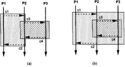
As an example of this, consider again the system described in Fig. 3. Suppose it is required to identify two atomic actions in this system:
AA,, i.e., AA, 2 AAb.
A&, i.e., AAb
a
AA..1) to protect c 1 ->c2, in process P1, and 2) to protect c3->c4, in process P3.
This might be attempted (incorrectly) as shown in Fig. 7a. However, by using the algorithms described, the atomic action to protect c3->c4 is given by:
TYRRELL A N D CARPENTER CSP METHODS FOR IDENTIFYING ATOMIC ACTIONS IN THE DESIGN OF FAULT TOLERANT CONCURRENT SYSTEMS 635
P I PZ P3
P i P2 P3
(a) (b)
Fig. 7. (a) Incorrect attempt to nest atomic actions; P3 could leave its “atomic action” with P2 before P2 has completed the “atomic action” with P1; (b) Correct nesting: the atomic action between P1 and P2 must include P3 and P3 cmnot leave until the atomic action is complete.
K = {al, bl, d l } and J = {a3, d3, b5}. (Example 2c)
This actually gives the entry and exit lines shown in Fig. 7b. Thus, the outer atomic action encloses the inner action com- pletely, making the nesting correct.
VII. STRUCTURAL ARGUMENTS IN ATOMIC ACTION IDENTIFICATION
The technique discussed so far requires full trace evalua- tions to identify atomic action boundaries. However, even with automated tools such as CoPla, the demands on system re- sources may become too great to allow full trace evaluations. For example CoPla requires 1.7MB of memory for the pro- gram, plus approximately (24 x number of traces x average length of trace) bytes for its data structures. Clearly, for real- world systems some means of avoiding full trace evaluation is advisable.
Structural arguments suggest that it is possible in many de- signs to avoid a full trace evaluation and still recognize atomic action boundaries. By and large the structure of the interproc- ess communications determines the location of atomic action boundaries. Local events (e.g., logical and arithmetic evalua- tion, and assignments) are of no interest, nor are constructs governing their sequence (such as loops and conditional selec- tion constructs) if they contain no interprocess communication. Thus, for example, during trace evaluation any sequence of assignments can be collapsed into a single event, simplifying the analysis. It is possible to generate the sets J and K (and thus identify the boundaries) without the need for full trace evaluations.
It is assumed, as earlier, that the designer has chosen a se- quence of consecutive events in one process (e$ - >
. . .-
> e& within process Pp). The sequence must be chosen to enclose fully any internal parallel or selection con- structs, and the description must be well-structured (in the sense that it can be translated into an Occam implementation). The designer wishes to determine where the atomic action boundary which encloses this sequence must lie. More pre- cisely, the question is which other processes are involved in the atomic action and where does the boundary lie within theseprocesses. The following algorithm determines which events must be included within the atomic action, thereby allowing the designer to defme its boundary and to identify all other processes which must be party to the atomic action, without having to produce the complete trace set for the whole system.
A. Algorithm 3
The algorithm marks those events which must be party to the
atomic action. Let {e:l, e : , } , the set of the fist and last events to be protected in process P,. a(Pp) has its usual meaning as the alphabet of the process P,. Then, define the primitive functions:
TXJ&J which determines whether its argument, “x,” is a local event (localevent), a communication event (comm), a sequential process (SEQ), a parallel process, a choice process or a guarded choice process.
Value(x) which expects an event as argument and returns its value (i.e., its name).
Markedrx) which returns a BooIean indicating whether the event or process, “x,” has already been recognized as part of the atomic action.
InsertMark(x) will cause Marked(x) to return TRUE on its next call.
Llst(N)
which is an ordered list of the events in the proc- ess given as its argument (effectively the trace restricted to the events in process N).The following auxiliary functions simplify the analysis:
Markraj modifies the marked attribute of its argument, “a,” setting it to the value TRUE; if the element is a communi- cation event then the other participant is also marked.
Mark(a):
( M a r k e W ) +
(q
(x E(4.)))
1) InsertMark(x);2) (Type(x) = comm)-> (y := Partner(x));
Mark@); 3) result := TRUE;
ment, returns the other participant.
Partner0
Partnerral, given a communication event “a” as argu-
(3x)
I
(x E ( a(P))) (Type(x) = comm)A(Value(x)= Value(a))A(x # a)->result := x;
SequentiallyPostDependent(a, b.
N)
determines whether event “b” is sequentially post dependent on “a”; in other words whether “b” must necessarily occur after “a” has finished. ( x > y means that “x” occurs after ‘‘y” in the or- dered list of N).SeauentiallvPostDeDendent (a, b.
N):
(a E a(N))A(b E W ) ) A
(W
I
(x E (List@))) (a E ( ~ X ) ) N J E (a(x)))-> [image:8.616.102.303.114.222.2]636 IEEE TRANSACTIONS ON SOFTWARE ENGINEERING, VOL. 21, NO. 7, JULY 1995
(3Y)
I
(Y E (LiSt(N)))A((b E a(y))A(X'Y))-' result := TRUE;Then the function FindAA:
Step 1) Marks all the events in the set of events E which have to be protected.
Step2) Ensures that all events between any two events that have to be executed in sequence are included within the boundary. For each marked event x in P, for each marked event y which is sequentially post dependent on x, mark all the events which are sequentially between x and y.
Step 3) Ensures that all processes can exit at the same time.
For each marked event x in P:
(a) define the empty set H. Insert into H all nonmarked communication events y that are sequentially post dependent of x. In- clude both participants.
For each element y of the set H, for each event z that is sequentially post dependent of y:
(b) if z is marked then mark y. If there has been any newly marked event then reit- eration of step 2 is needed.
(c) if z is not marked and it is a communication event then if z or its partner do not belong to H include them and reiterate step 3b.
FindAA():
Step 1) (Vx)
1
(x E E)+Mark(x) Step 2)a) (Vx)
I
(x E (a(P))) (VY)I
(Y E ( W ) ) )(Marked(x)) ~ ( M a r k e d ( y ) ) ~ (SequentiallyPostDependent (y, x, P))+
(V-4
I
(z E (a(P)))(SequentiallyPostDependent(z, x, P))A (SequentiallyPostDependent(y, z, P))+
(Mark(z))+goto2 := TRUE;
Step 3) (Vx)
I
(x E (a(P))) A (Marked(x))b) (goto2)+go to step 2a
a) H : = {};
(VY)
I
(Y E "((Marked(y)) A (Type(y) = CO")A
(SequentiallyPostDependent(y, x,
P))+
H := H U y U Partner(y); b) (VY)
I
(Y E (HN (Vz)I
(z E (Oc(P)))(SequentiallyPostDependent(z, y, P)) A
(Marked(z))+Mark(y)&goto2 := TRUE; c) (VY)
I
(Y E (H)) (Vz)I
(z E (Oc(P)N(SequentiallyPostDependent(z, y, P))A (Marked(z)) A (Type(z) = CO") A ((z G H) v
(Partner(z)
e
H))+H := H U z U Partner(z); goto3.b := TRUE;d) (goto3.b)+go to step 3.b Step 4) (goto2)+go to step 2
The algorithm seeks out communication pattems amongst the set of processes in an iterative fashion and deliberately examines the sequential dependence of communications in the system. It uses this sequential dependence to examine not only all direct communications with the original sequence requiring protection, between the events in set E, but also any subse- quent communications (set H) from processes with which events in E have had contact. It determines whether these sub- sequent communications have structural implications which require their inclusion in the atomic action. The algorithm'it- erates until no further events are identified for inclusion in the atomic action.
The algorithm progressively marks those events in the complete set of processes which should be included in the atomic action. The final step is to generate the set AAe which identifies the events constituting the atomic action, and the set AAP to determine which processes are necessarily party to the atomic action.
1. Define the empty set AAe
2. Add each marked event to AAe AAe := { }
(Vx)
I
(x E (NP))) A (Marked(x))->AAe := AAe U x 3. Define the empty set AAP
AAP := (}
4. For each event x in AAe, for all processes P,, if e E NP,) then add P, to set AAP.
(Ve) (VP,)
I
(e E AAe)A(e = a(Pp))-> AAP := AAP U P,These structural algorithms have been applied to a large number of examples.
VIII. EXAMPLES
Consider again the set of processes given in Fig. 3:
P=(Pl IIPzIIP3) where
P 1 = (al->cl !->aZ->c2?->d->SKIP)
P2 = (bl ->c I?->b2->~3!->b3->~4?->M->c2!->b5->SKIP) P3 = (dl ->c3?->dZ->d!->d3->SKlP)
Atomic actions can be readily identified without the need to evaluate the traces given in Fig. 4.
EXAMPLE
1 REVISITEDSuppose it is decided to protect event c l . Hence E = (cl}. Then step 1 causes the following marking of events
(0
indicates marked events).PI = ( a l - > m ->aZ->c2?->d->SKIP)
P2 = ( b l - > a ->b2->~3!->b3->d?->b4->~2!->bS->SKlP)
TYRRELL AND CARPENTER: CSP METHODS FOR IDENTIFYING ATOMIC ACTIONS IN THE DESIGN OF FAULT TOLERANT CONCURRENT SYSTEMS 631
Step 2 leads to no new markings, and consequently the al- gorithm gives AAe = { c l ) and AAP = {PI, P2). In other words the atomic action enclosing event c l includes only the event c l in both processes P1 and P2. This is consistent with the earlier analysis that the atomic action begins immediately after event a1 in process P1 and event b l in process P2, and terminates immediately before event a2 in process PI and event b2 in process P2.
EXAMPLES 2A, 28,2C REVISITED
In a similar way, these produce analogous results to those produced earlier using algorithm 1.
EXAMPLE 3 REVISITED
Here the designer has the opportunity of selecting to protect either d2 alone, but to include other events in the sequence c3
-> d2->c4 in P3. For E = {d2), algorithm 3 quickly terminates with AAe = {d2) as the sole constituent of the atomic action. However, if E = {c3, d2) were selected, then step 1 would cause the following marking:
PI = (al->cl!->a2->~2?->a3->SKIP)
P2 = (bl->cl?->b2->m ->b3->c4?->b4->~2!->bS->SKIP)
P3 = ( d l - > v l ->c4!->d3->SKIP)
giving AAe = {c3, d2) and AAP = {P2, P3).
cause the following marking:
Likewise, if E = {d2, c4) were selected, then step 1 would
PI = (a1 ->cl !->a2->~2?->a3->SKIP)
P2 = ( b I - > c l ? - > b 2 - > ~ 3 ! - > b 3 - > ~ ->b4->~2!->bS->SKlP)
P3 = (dI->c3?->= ->d3->SKIP)
giving AAe = {d2, c4) and AAP = {P2, P3).
However, if E = {c3, c4) were selected, then step 1 and step 2 would cause the following marking:
PI = (al->cl!->a2->~2?->a3->SKIP)
P2 = (bl->cl?->b2->lc3!->b3->c4?1 ->b4-%2!->bS->SKIP)
P3 = (dI->lc3?->dZ->c4!1 ->d3->SKIP)
giving AAe = {c3, d2, c4, b3) and AAP = {P2, P3).
EXAMPLE 4 REVISITED
This example concems the set of processes:
P = (PI 11 P2 11 P3)
where
P 1 = (a I ->c I !->a2->~2?->a3->~3?->a4->SKIP) P2 = (bl->cI?->b2->~2!->b3->~4!->b4-->SKIP) P3 = (dl->c4?->d2->~3!->d3->SKIP)
As before, suppose it is decided to protect the sequence cl!->a2->~2?->a3->~3? in process P1, i.e., E = {cl, c3). Then
step 1 causes the marking:
PI = ( a l - > m ->a2->c2?->a3->a ->a4->SKIP)
P2 = ( b l - > a ->b2->~2!->b3->~4!->b4-->SKIP)
P3 = (dl->c4?->d2->m ->d3->SKIP)
Step 2 now causes the marking:
PI = (al->l cl!->a2->~2?->a3->~3?1 ->a4->SKIP)
P2 = (bl->m - > b 2 - > m ->b3->~4!->b4-->SKIP)
P3 = (dI->ul?->d2->m ->d3->SKIP)
This step is reiterated, since new events were marked:
P1 = (al->l cI!->a2->~2?->a3->~3?1 ->a4->SKIP)
P2 = (bl->lcl?->b2->c2!1 ->b3->d!->b4-->SKIP)
P3 = ( d I - > d ? - > d 2 - > m ->d3->SKIP)
Now step 3a looks at the unmarked communications events, to form the set H = {c4!, c4?). Step 3b would discover that c3! in process P3 is marked and sequentially post dependent, leading to the marking:
PI = (al->l cl!->a2-~2?->a3->~3?1 ->a4->SKIP)
P2 = (bl->lcl?->bZ->c2!1 - > b 3 - > m ->b4-->SKIP)
P3 = (dl->@ - > d 2 - > m ->d3->SKIP)
Reiteration of step 2 then leads to the marking:
PI = (al->[ cl!->a2->~2?->a3->~3?I ->a4->SKIP)
P2 = (bl->l cl?->b2->~2!->b3->~4!I ->b4-->SKIP)
P3 = (dl->[c4?->d2->c3!1 ->d3->SKIP)
No further markings are generated by the remaining steps, leading to the conclusion that AAe = {a2, a3, c l , c2, c3, c4, b2,b3,d2) andAAP= {pl,p2,p3).
B. Complexity of the Algorithms
The full trace algorithm (algorithm 1) would show expo- nential complexity with the number of processes during trace production if there were no synchronizing communications present. When communications are added, each communica- tion forces synchronization between two processes, eliminates part of the trace set, and thus reduces complexity. Every com- munication reduces the size of the trace set significantly, and similarly the time required to search. Thus:
Given n processes, each with m events, and 0 comms:
Given n processes, each with m events, and 1 comms:
Given n processes, each with m events, and p comms:
Searching is approximately linear with the size of the trace set, since the algorithm is simply scanning the trace sets.
In algorithm 3, this initial complexity does not appear as traces are not explicitly produced. Instead, complexity arises in searching across communication links to identify atomic action boundaries. Algorithm 3 shows a near linear complexity, but whenever sequential post dependency forces backtracking the analysis becomes less obvious. If there were no backtracking, then the complexity would be linearly dependent on the num- ber of events (n*m). Every time the algorithm has to back- track, it is effectively analogous to regenerating a further set of traces to search. Thus, if there are q backtracking occurrences, then the complexity increases to n*m*q.
require about nm traces.
require about 2.nmI2 traces.
638
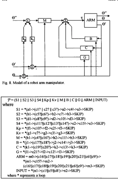
P = (SI I/ S2 I1 S3 I1 S4 I1 Kp I1 Kv II M II B /I C II G II ARM I1 INPUT)
{here
SI = *(al->(cl? jl c2? 11 c3?)->a2->c4!->a3->SKIP) S2 = *(bl->(c5?l/c6?)->b2->~7!->b3->SKIP)
S4 = *(el->(cl l?)~c12?~~~13?~/~14?)-~e2->~15!->e3->SKIP) Kp = *(fl->clO?->fZ->c2!->f3->SKIP)
Kv = *(gl->c7?->gZ->c3!->g3->SKIP) M = *(hl->(c4?llcl6?)->h2->cI I!->h3->SKIP) B = *(i l->(cl7?~~cl8?)->j2->~14!->j3->SKIP)
C = *(k 1 ->(c 19?11~20?)->kZ->c I3 !->!&>SKIP)
G = *(11->~21?->12->~12!->13->SKIP)
ARM = tnO->(c16!~~~17!~~cI 8 ! ~ ~ ~ 1 9 ! ~ ~ ~ 2 0 ! ~ ~ ~ 2 1 ! ~ ~ ~ 6 ! ~ ~ ~ 9 ! ) - > S 3 = ‘(dl ->(~8?(/~9?)->d2->cl O!->d3->SKIP)
*(ml->cl S?->m2->
(c16!~~c17!~~c18!~~c19!~~c2O!~jcZ1!~~c6!~~c9!)-~m3-~SKIP) INPUT = *(nl ->(c I !IlcS!llcX!)->n2->SKIP)
,
where*
represents a loop [image:11.615.105.308.91.399.2]IEEE TRANSACTIONS ON SOFTWARE ENGINEERING, VOL. 21, NO. 7, JULY 1995
Fig. 8. Model of a robot arm manipulator.
IX. A REAL WORLD EXAMPLE
Simple examples as shown above can have their trace se- quences evaluated “by hand” and boundary identification can be achieved by inspection of the trace sets. For larger, more realistic examples manual methods become m a n a g e a b l y complex. The CoPla software tool has been used to produce trace sets for a number of more complex systems and then used to identify atomic action boundaries. One application, a robot arm manipulator, (Fig. 8) has been modeled [25] and imple- mented as a set of 12 parallel processes. A slightly simplified version expressed in CSP is shown in Fig. 9; following initiali- zation, each process engages in an infinite loop, all synchro- nized by communications. (The CSP description expands to an
actual implementation comprising about 10,000 lines of occam code). Automated analysis reveals 184,900 possible traces; CoPla then allows the user to propose entry and exit points for an atomic action within one of the processes and uses the al- gorithms described earlier to determine the proper boundaries of the atomic action.
For example, consider the requirement to locate an atomic action boundary which encloses c15 to c9 inclusively in proc- ess ARM. CoPla gives the following results:
En2=(c6) ES1=(c9) ESr=(c15) E ~ = ( c l 6 ) Ee = ( ~ 1 7 , CIS) Ec = ( ~ 1 9 , ~ 2 0 ) & = ( ~ 2 1 )
EARM= (c15, m2, c16, c17, c18, c19, c20, c21, c6, c9)
allowing the sets K and J to be derived as:
K = {bl, d l , e2, h l , j l , k l , 11);
events which must precede the atomic action boundary, and
events which must follow the atomic action boundary. J = (b2, d2, e3, h2, j2, k2,12};
X. CONCLUSIONS
This paper has proposed two methods for identifying atomic actions in systems described using CSP. If explicit trace evalua- tion is tractable, then algorithms 1 and 2 provide the designer with a systematic method of locating atomic action boundaries in a hierarchical fashion, essentially by analyzing the possible se- quences of interprocess communications within the trace sets. The second method (algorithm 3) takes the original CSP de- scriptions of the system and uses structural arguments to identify the atomic action boundaries; this method does not suffer the drawbacks involved in full trace evaluation, but does incur the penalty of a more complex algorithm.
Both techniques identify those events which are constitu- ent to a proposed atomic action and eliminate all processes that are disjoint from the atomic action; both techniques al- low nested atomic actions to be identified correctly. How- ever, an analysis based on structural arguments has a number of attractions. By avoiding a full trace evaluation or a full reachability analysis, the method is more economical on computational time and memory resources. But, it depends implicitly on the ability to analyze the sequence in which events could occur, which is akin to the ability to generate the complete set of traces. It cannot therefore be used with an arbitrary set of communicating processes; the designer is restricted to processes formed solely from sequential, paral- lel, conditional and general choice constructs of simple events and communications. Nevertheless, the algorithms have been applied to systems which include restricted forms of program loops. For example, the robot manipulator arm processes are normally invoked from within an infinite con- trol loop, but since the iterations begin and end synchro- nously, the analysis can be applied without prejudice.
639 TYRRELL A M ) CARPENTER CSP METHODS FOR IDENTIFYING ATOMIC ACTIONS IN THE DESIGN OF FAULT TOLERANT C O N C W N T SYSTEMS
be produced. When the problem of atomic action placement is addressed, for such situations, the main point is that the complete “nondeterministic” structure (such as an Occam ALT) must be included in the atomic action.
Both methods operate directly on the CSP description of the system. They require no error prone translation of a de- veloped program into graphical form, nor is there an implied simulation of program execution based on the graphical structures. Furthermore, translation of the CSP design to an occam implementation is generally straightforward (since problematic features such as interrupts are excluded) because of the close family relationship between Occam and CSP, or alternatively, hardware implementations can be developed directly from the CSP design with only modest difficulty.
The underlying motivation of this research is to develop a mechanism for introducing software fault tolerance struc- tures in a systematic, proper, fashion. Atomic action identifi- cation is just the first, crucial, step in that process.
ACKNOWLEDGMENTS
The authors would like to thank Oscar Saiz for his work on implementing some of the algorithms presented in this paper. Thanks also to the anonymous reviewers for their constructive comments which have helped improve the paper.
REFERENCES
MOD(UK) Interim Defence Standards 00-55 and 00-56, no. 1, Apr. 1991. “Software considerations in airbome systems and equipment certifica- tion,” RTCA/D, 178A RTCA, Washington, DC, 1985.
“Software for computers in the application of industrial safety-related systems,” IEC drafl standard 65A (Secretariat) 94, Document 89/33006, BSI, 1989.
A. Avizienis, and J.P.J. Kelly, “Fault tolerance by design diversity: Concepts and experiments,” IEEE Computer, vol. 17, no. 8, pp. 67-80,
*..” I n o r
rws. l70Y.
P.A. Lee, and T. Anderson, Fault Tolerance: Principles and Practice.
Springer Verlag, 1991
B.H Liskov and R. Scheifler, “Guardians and actions: Linguistic support for robust, distributed programs,’’ ACM Trans. Program. Lang. Syst., vol. 5 , no. 3, pp. 3 8 1 4 0 4 , July 1983.
P. Jalote and R.H. Campbell, “Atomic actions for fault tolerance using CSP,” IEEE Trans. Software Engineering, vol. 12, no. 1, pp. 59-68, Jan. 1986.
T. Anderson and J.C. Knight, “A framework for soflware fault tolerance in real-time systems,” IEEE Trans. Software Engineering, vol. 9,
no. 12, pp. 355-364, May 1983.
C.A.R. Hoare, Communicafing SequentialProcesses. F’rentice Hall, 1985.
[IO] L.V. Mancini, and S.K. Shrivastava, “Replication within atomic actions and conversations: A case study in fault-tolerance duality,” FTCS-19,
Chicago, pp. 4 5 4 4 6 1 , June 1988.
[ l l ] B. Randell, “System structure for software fault tolerance,” IEEE Trans. Software Engineering, vol. 1, pp. 22&232, June 1975.
[I21 A. Avizienis, “The N-version approach to fault-tolerant software,” IEEE
Trans. Soflware Engineering, vol. 11, no. 12, pp. 1,491-1,501, Dec. 1985. [13] R.K. Scott, J.W. Gault, and D.F. McAllister, ”Fault-tolerant software
reliability modeling.” IEEE Trans. Software Enaineerinz, vol. 13, no. 5 , pp. 583-592, May-1987.
[I41 K.H. Kim, and H.O. Welch, “Distributed execution of recovery blocks: An aooroach for uniform treatment of hardware and software faults in
..
real-time applications,” IEEE Trans. Computers, vol. 38, no. 5, pp. 626-636, May 1989.[I51 E. Best, and B. Randell, “A formal model of atomicity in asynchronous systems,” Acta Informutica, vol 16, pp. 93-124, 1981.
[I61 K.H. Kim, S.M. Yang, and M.H. Kim, “Implementation of concurrent programming language facilities supporting conversation structuring,”
Proc. IEEE COMPSAC ‘85, pp. 4 4 5 4 5 3 , 1985.
[I 71 K.H. Kim, “Programmer-bansparent coordination of recovering concurrent processes: philosophy and rules for efficient implementation,” IEEE Tram. Sofhare Engineering, vol 14, no. 6, pp. 810-821, June 1988. [IS] K.H. Kim and S.M. Yang, “Performance impact of look-ahead execu-
tion the conversation scheme,” IEEE Trans. Computers, vol. 3 8 , no. 8,
pp. 118-1,202, Aug. 1989.
[I91 R.H. Campbell, T. Anderson, and B. Randell, “Practical fault tolerant software for asynchronous systems,’’ Proc. SAFECOM ‘83, Cambridge,
pp. 5 9 4 5 , 1 9 8 3 .
[ZO] G.F. Carpenter, “The use of Occam and Petri nets in the simulation of logic structures for the control of loosely coupled distributed systems,” Proc. UKSC Conference on Compuler Simulation (UKSC-87), Bangor, Sept.
1987. Pub. Soc. Computer Simulation, pp. 3&31, Sept. 1987.
[21] G.F. Carpenter and A.M. Tyrrell, “The use of GMB in the design of
robust sofhvare for distributed systems,” Software Engineering J., vol.
4, pp. 268-282, Sept. 1989.
[22] J.L. Peterson, Petri Ne1 Theory and the Modeling ofSystems. Prentice Hall, 1981.
[23] Inmos, Occam 2 Reference Manual. Prentice Hall, 1988.
[24] A.M. Tyrrell, and A.C.A. Smith, “A parallel module for fault tolerant industrial control applications,” IFAC Symp. Parallel and Distributed Computing, Greece, pp. 205-210, June 1991.
[25] A.M. Tyrrell, and I.P.W. Sillitoe, “Evaluation of fault tolerant software structures for parallel systems in industrial control,” IEE Int. Con/:
CONTROL ’91, Edinburgh, pp. 393-398, Mar. 1991
[26] G.M. Reed, and A.W. Roscoe, “A timed model for CSP,” Theoreficol
Computer Science, vol. 58, pp. 249-261, 1987.
[27] 2. Chaochen, “The consistency of the calculus of total correctness for communicating processes,” Oxford Univ. Research Group Monograph PRG 26, Feb. 1982.
[28] O.J. Saiz, and A.M. Tyrrell, “Analysis tool for parallel systems,” Proc.
First Euromicro In1 ‘I Workshop on Parallel and Distributed Process- ing, Gran Canaria, Jan. 27-29, 1993, IEEE Computer Society Press, pp.
499-505, Jan., 1993
[29] A.M. Tyrrell, and D.J. Holding, “Design of reliable software in distrih- uted systems using the conversation scheme,” IEEE Trans. Sofmare Engineering, vol. 12, no. 7, pp. 921-928, Sept. 1986.
[30] K.H. Kim, “Approaches to mechanization of the conversation scheme based on monitors,” IEEE Trans. Software Engineering, vol. 8, pp. 189-197, May 1982.
Andrew M. Tyrrell received a first class honors degree in 1982 and a PhD in 1985, both in electrical and electronic engineering. He joined the Electron- ics Department at York University in April 1990. Previous to that, he was a senior lecturer at Coventry Polytechnic Between August 1987 and August 1988 he was visiting research fellow at Ecole Poly- technic, Lausanne, Switzerland, where he was re- searching into the evaluation and performance of multiprocessor systems From September 1973 to
September 1979 he worked for STC at Paignton Devon on the design and development of high frequency devices. He is cur- rently head of the Parallel and Signal Processing Research Group at York.
His main research interests are in the design of parallel systems, fault tolerant design, software for distributed systems, parallel systems for numeri- cal problems, real-time simulation using parallel computers and real-time systems. In the last five years he has published over 40 papers in these areas, and has attracted funds in excess of €250,000.
Dr. Tyrrell is a member of the IEE, the IEEE and the ACM.