THE WORLD'S FIRST . ...
S-100 Single Board Computer
TECHNICAL MANUAL
for
SUPER QUAD
INTRODUcrION
ADVANCED DIGITAL CORPORATION is proud
to
introduce the SUPER QUAD.
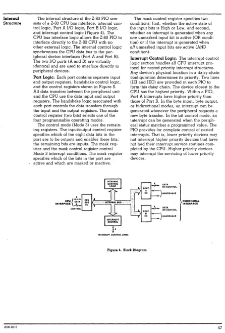
The SUPER QUAD is a Z80 based single board computer designed to be
a bus master in an SIOO bus system. The SUPER QUAD SOC has all the
hardware needed to run a single user CP/M system or 2 user MP/M
system with up
to
4 external floppy disk drives and an external
Centronics parallel interface printer all on one board.
The board also runs with TURBO-LOS
Un.
The SUPER QUAD SEC contains:
1)
Z-80A cpu
(4 MHZ)
2)
Floppy disk controller
(up to 4 drives 8" or 5!:i" )
3)
64K of dynamic
merrory
(16K bank selectible)
4)
2K or 4K of shadow eprom
(2716 or 2732)
5)
2 serial ports
(Z80A SIO opt. syncronous)
6)
2 12 bit parallel ports,
(Z80A PIO)
one of which can be used
for SIOO vectored interrupts
7)
Real
t~einterrupt clock
(Z80A CTC)
8)
SIOO extended address Al6-A23
ONE YEAR WARRANTY.
*Note:
Items 5 and 6 require external adaptation for RS-232 and
Centronics. The adapter boards are 2 x 2" and are called
PS NET.
They hoop up to the back of the main frame with
TABLE OF CONTENTS
Page
Introduction
.
.
.
.
.
. .
.
. .
.
.
.
. . . .
.
. . .
.
. . .
.
.
.
.
.
. . .
.
.
.
. .
.
. .
1
Table of Contents •••••••••••••••••••••••••••••••••••••••••••••• 2,3
1.0
2.0
Operation •••••••••••••••••••••••.••••••••••.•••
1.1
Floppy disk •••••••••.••.•••••••••••••••
1.2
64 K Dynamic Ram •••••
~•••••.••••••••.••
1.3
Monitor Eprom ••••••••••••••••••••••••••
1.4
Serial Ports •••••••••••••••••••••••••••
1.S
Parallel Ports •••••••••••••••••••••••••
1.6
Real Time Clock ••••••••••••••••••••••••
1.7
5100 bus interface •••••.••••••••.••••••
EPROM
2.1
2.2
2.3
2.4
alld Moni tor ••••.•••••••••••••••••••••••••
Enable
I
Disable software ••••••••••••..•
Monitor Sign-on ••.•••••.••••••••••••••••
Monitor Commands •••••••••••••••••••••••
Cold boot loader program •••••••••••••••
4
4
S
S
5
6
6
7
7
8
8
9
3.0
Input / Output port assignments •••••••••••••••••
10
4.0
Input / Output port description
11
4.1
·SIO serial port channel A •••••••••.••••
11
4.2
SIO serial port channel B •••.••••••••••
11
4.3
PIO parallel port channel
A ••••••••••••
11
4.4
PIO parallel port channel
B ••••••••••••
11
4.S
Control timet
Interrupt circuit •..••••
11
4.6
Floppy Disk controller ••••••••••.••••••
11
4.7
Floppy disk control port ..••.••••.•••••
12
4.8
Extended address port •••••••••••••.••••
13
4.9
On-board memory control port .••••••••••
14
S.0
Jumper definitions •••••••••••••.••••••••.••.•••
15
6.0
Jumper
6.1
6.2
6.3
6.4
6.S
6.6
6.7
6.8
6.9
6.10
6.11
6.12
descriptions
.
.
. .
.
. .
.
. .
. .
.
. . .
.
.
. .
.
.
. . .
Jumper
A
-
CPU clock rate
...
Jumper
B
-
S10 channel
A
clock
. . .
.
Jumper C
-
SIO channel
B
clock
.
.
. . .
.
. . .
Jumper
D
-
Drive type selection
. .
.
. . .
Jumper
E
-
VIa
I
PI
N'I'
. .
.
.
. . . .
. .
. .
.
. . .
Jumper
P
-
VIa
/
paralled bit
D0
·
...
Jumper N
-
VII
/
paralled bit Dl
·
.
. . .
.
.
Jumper
tvl
-
VI2
/
paralled bit D2
·
.
. .
.
.
.
Jumper
K
-
VI3
I
paralled bit D3
· .
.
. .
. .
Jumper J
-
VI4
/
paralled bit D4
· ...
Jumper
H -
VIS / paralled bit DS
Jumper G - VI6 / paralled bit D6
2
IS
16
16
17
18
18
18
7.0
8.0
6.13
6.14
6.15
6.16
6.17
Baud
7.1
Jumper F -
VI7 / paral1ed bit D7 • . . . • . .
19
Jumper
R -
2716 / 2732 ..•••....••..•.••
19
Jumper S -
Floppy connector • . • . . • • . . • • •
Jumper T -
Memory Write Signal •••••••••
20
Jumper layout •..••••.•••.••••••••••••.••
AA
Rate Switch •••••.•••••••.•.•••..••••••••••
Switch Setting
21
21
External Connector pin definitions ••••••..•••••
22
22
23
24
25
25
8.1
8.2
8.3
8.4
8.5
Jl
J2
J3
J4
J5
-
5100
bus ••••••••••••••••••••••••••
Parallel Port •.•••••••••••••••••••
Floppy Disk controller ••••••••••••
-
Serial port channel A .••••••••••••
Ser ial port channel
B •••••••••••••
9.0
Bloc\<. D i a g r a m . . .
26
10.0
Factory
10.1
10.2
10.3
10.4
10.5
10.6
10.7
10.8
10.9
10.9.1
Installed Jumpers ••.•••••.•••••••••••••
8 inch drive configuration •••••••••••••
5.25
inch drive configuration ••.•••••••
Shugart 800 drive .•••••••.•.•••••••••••
sl:'lugart
850 . . . .
MP I d
r
i
v e . . • . . . • . . . • . • • • . . .
M
FE
n\
0del 7 0 0 • . . . .
TANDON SLIM LINE .••.•••••••••••••••••••
NEC model FDl160 ••••.•.•••.••••••••••.••
QUME Data Track 8 •••••••••••••••••••••••
'l'ANDON 5 1/4" •••••••••.••••••.••••••••••
27
28
29
30
31
11.0
Appendex
& Data sheets .•••••...••••••.•••••••••
32
12.0
13.0
11.1
11.2
11.3
11.4
11.4.1
11.5
11.6
11.8
11.9
11.10
Appendex A
Z80A SIO / DART ••••.•..•••
Appendex B -
Z80A PIO .•••••••••••••••••
Appendex
C -
Z80A CTC .•••••••••.•••.•••
Appendex
0 -
Floppy Disk controller ••••
W'D 1 6 9 1 ,
B
R 1 9 4 1 • • • • . . • • • • • • . . . • • • • . • • • • • •
Appendex E -
Z80A CPU .•••••••••••••••••
Appendix F-
FLOPPY ERROR CODE ••..••.•.•
War'
rant't1 •••••.•.•••..••••••.•••.•.••••••
Application notes:
Turbo-Dos app. notes .••
Additional memory boards • • . . .
Recomended additional 5-100 boards:
Hard disk:
morrow designs,konan,xcomp
Memory: measurement systems,PCE
Graphics: micro angelo
Slave Processor: Advanced Digital,
MUSYS
corp.
Parts l i s t
'1.1
The Floppy Disk Controller
The floppy disk controller can access up to four 8 inch or
5.25
inch floppy disk drives. It can read and write IBM 374g single
density format and double density 128,256,512,lg24 sector size
formats. Data transfer is done by programmed I/O with wait and
interrupt syncronization.
Note: The controller cannot access both 8 inch and 5.25 inch drives
simultaniously,The controller is switched from 8 inch to 5.25 inch
drives by hardware jumper options.
1.2
The 64 k Dynamic ram
The 64 k ram array can be switched on and off in 16 k increments
(0-16K,16K-32K,32K-48K,48K-64K) under software control. This allows the
CPU to access bank switchable external memory on the 8100 bus.
The memory has an access time of 2000s. Refresh is done during
Z80 Ml cycles and during wait and reset states. The memory can
be accessed by an external DMA device on the 5100 bus.
Note : Any external DMA device that is using continous mode DMA
cycles must transfer data at an average rate of 15 us
per byte or
faster when holding the DMA request line for more than 1.5 ms This is
not a problem because most designers are smart enough to use
byte-at-a-time or burst
transfer modes when dealing with slow DMA
transfer rates. The ram row address is the low order addtess
there-for the entire ram array is refreshed by the DMA device every 128
contiguous memory cycles.
1.3
System Monitor Eprom
The system monitor eprom is switched on during reset. I t can be
disabled and enabled under software control. I t resides when
enabled at F000h to FFFFh. It has commands that allow the user
to load the CP/M, MP/M or other boot loaders from floppy disk.
In addition it can be used to load , examine goto and test
memory. When the prom is disabled. it does not use any system address
space.
1.4
Serial ports
A Z80A DART is used for the two serial ports , but
a ZB0A SIO/0 chip can be used in i t ' s place. This allows
asyncronous and synchronous serial data communications plus a variety
of interrupt modes. Modem control signals are available at each
serial connector. There are two switch selectible baud rate
generators for baud rates of 50 to 19.2 k baud.
Note : The serial ports are TTL and must be connected to external
interface boards for RS232
communications.
(PS NET/I)
1.5
Parallel ports
A Z80A PIO is used as the parallel port. The "A" channel of this
chip
is connected to the parallel port connector. This port has 8
bi-dir-ectional data lines and two hand shake lines. The
"B"
port can be split
between the parallel port connector and the S100 bus vectored interrupt
lines by jumper options. This allows the port to be used as an
additional parallel port or interrupt controller or both.
1.6
Real Time Interrupt clock
A
ZaCA
CTC is used for providing a real time system clock fOl MP/M.
Three channels of the CTC
are available to the user for strapping via
a jumper header for synchronous baud rates or long clock times.
1 .?
S100
Bus Inter face
The Sl00 bus interface provides the signals necessary for an 8 bit
bus master as described by the IEEE 696 bus specification.
Vectored interrupt lines VI0 - VI? are supported via jumper options
and A16 - A23 are also supported vis an I/O port.
#
The PAMNTON line is also implemented for the dynamic ram array.
2.~
EPROM and Monitor operation
The onboard EPROM occupies address
F~~~H-FFFFH.The EPROM
is switched on automatically during reset or power on, the
EPROM contains SIO and Foe initialization code along with a
simple debugger and floppy disk cold start loader. After
the operating system is loaded the EPROM can be turned off
so that the ram at address F000H-FFFFH can be accessed. The
EPROM can be turned on and off at any time so that hardware
dependent I/O routines can be called.
2.1
Eprom Enable / Disable
Switching EPROM on :
F033 3E4F
MVI
A,~l001l11BiRESET POWER ON JUMP
i
AND ENABLE MEMORY, EPROM ON
F035 0316
OUT 168
iWRITE TO CONTROL PORT
Switching EPROM off
F033 3E4F
MVI A,0110l111B iRE5ET POWER ON JUMP
; AND ENABLE MEMORY, EPROM OFF
F035D316
OUT 16H
iWRITE TO CONTROL PORT
Jumper R configures
the board to accept a 2716 or 2732 EPROM.
Note : The EPROM is always addressed at F800H and can not
be moved. Since the 2716 EPROM is 2K long it appears
twice , F800H-FC00H and FBFFH-FEFFH.
2.2
Monitor 5ignon
The EPROM contains a simple debugger.
The monitor signs on with
>
ADVANCED
DIGITAL CORP.
>
Monitor Version 1.1
Mar - 1982
Press "H" for help
The monitor commands are :
Control B
=
Load disk boot loader 5.25"
Control
C
=
Load disk boot loader 8 "
D SSSS
QQQQ
=
Dump memory in hex from
ssss
to
QQQQ
F
ssss
QQQQ
BB
=
Fill memory from SSSS to
QQQQ
with BB
G
AAAA
=
Go to address AAAA
L AAAA
=
Load memory starting at AAAA
M
SSSS
QQQQ
DO
=
Move from S to
Q
to ADDR DO
P
SSSS
QQQQ
=
Print in ascii from SSSS to
QQQQ
T
=
Test Memory
ESC
will terminate any command
The cold boot loader will select and home drive
~.Track
0
sector
1
will be read into memory at location
0 •
•
Single
densi~y
is assumed for track 0.
If an error occures an error code will be printed.
The error code must be translated
using the table
in appendex F page F-4
fig
2.
e.g.
FDC COLD BOOT ERROR
80=
DISK NOT DETECTED
FDC COLD BOOT ERROR 10= WRONG FORMAT OR NO DATA ON DISK OR BAD PHASE LOC
LOOP.
2.4
Cold Boot Program
READ TRACK
0
SECTOR
1
INTO MEMORY
BOOT
5:
MVI
A,08H
OUT
WAIT
iset double for
5
inch
BOOT:
F4B5 3E0D
MVI
A,00H
iRESET FOC
F4B7 D30C
OUT
FDC
; ISSUE COt-1MAND
F4B9 00
NOP
FOCW1:
F4BA DB0C
IN
FDC
CHECK BUSY
F4BC 0F
RRC
F4BD DABAF4
JC
FDCWl
F4C0 00
NOP
KILL TIME
F4C1 00
NOP
F4C2 00
Nap
F4C3 00
NOP
F4C4 3E03
MVI
A,3
GET A RESTORE
E'4C6 D30C
OUT
FDC
ISSUE COMMAND
f'4CB
00
NOP
F4C9 OB14
IN
WAIT
WAIT FOR
E'4CB 00
NOP
INTRQ
'l'K 0 :
F4CC DBCC
IN
FOC
F4CE E604
ANI
4
CHECK TRACK "
E'4D0 CACCF4
JZ
TK0
F4D3 AF
XRA
A
F404 6F
MOV
L,A
POIN'l'
1\'1'
LOC
"
F405 67
MOV
R,A
F4D6 3C
INR
A
E'4D7 D30E
OUT
FDCSEC
SET SECTOR
F4D9 3EBC
MVI
A,08CB
GET READ COMMAND
F4DB 030C
ou'r
FOC
ISSUE COMMAND
F4DD
~0Nap
FDCRD:
E'4DE DB14
IN
WAIT
WAI'1' FOR INTRQ
F4E0 B7
ORA
A
OR ORQ
F4El F2EBF4
,JP
BOOTDN
EXI T I F I N'1'RQ
F4E4 DB0F
IN
FDCDATA
GET DATA
E4E6 77
MOV
M,A
S'I'ORE
F4E7 23
INX
H
paIN'!' NEXT
F4EB C3DEF4 .
JMP
FDCRO
BOOTON:
F4EB DB0C
IN
FDC
CHECK S,!'ATUS
F'4ED B7
ORA
A
o
=
NO ERROR
F4EE CA0000
JZ
0
OK, GO
F4F1 F5
PUSH
PSW
SAVE ERROR
F4F2 210FF6
LXI
H,BTERR
PRI N'l'
F4F5 CDE6F0
CALL
MSG
DISK ERROR
F4F8 F1
POP
PSW
GE'!, ERROR
INPUT / OUTPUT PORT ASSIGMENTS
Address
00
01
02
03
04
05
06
07
08
09
0A
08
0C
0D
0E
0F
10
11
12
13
14
15
16
17
18
19
1A
18
lC
ID
18
IF
Read/Write
Read/Write
Read/Write
Read/Write
Read/Write
Read/Wr i te
Write
Write
Read/Write
Read/Write
Read/Write
Read/Write
Read/Write
Read/Write
Read/Write
Read/Write
Read/Write
Write
Write
Function
510 Channel A Data port
SIO Channel A Status/Control Port
510 Channel
B
Data port
510 Channel
B
Status/Control Port
PlO Channel A Data port
PIO Channel
B
Data port
PIa Channel A Control port
PlO Channel B Control Port
CTC Channel
0
Control Port
CTC Channel
1 control Portal
CTC Channel 2 Control Port
eTC Channel 3 Control Port
FDC Command/States Port
FDC Track Register
FDC Sector Register
FDC Data Port
Unused
Unused
Unused
Unused
FDC Syncronization/Drive/Density
5100 Buss Extended Address A16-A24
On-Board Memory Control Port
Unused
Unused
Unused
Unused
Unused
Unused
Unused
Unused
Unused
All addresses are listed in Hexidecimal.
The unused input / output ports are internally decoded and
should not be used
by
external S100 I/O boards.
4.0
INPUT / OUTPUT PORT DISCRIPTIONS
4.1
Serial Communications Port
A
--~See 1\ppcndex A
00
Read/Write
SIO Channel A Data port
01
Read/Write
SIO Channel
A
Status/Control Port
4.2
seri.al Communications
Pott B ---
See Appendcx A
4.3
4.4
02
03
Read/Write
ReDo/WritE:
Paralled Interface
POlt
A
04
06
Read/Wr
i
te
\~ l'i
t€:
Parallel lnterface
Port B
SIO Channel B Data
port
S 1 0 C h
ilnne
jB S
t
i;.t
us /
Con
t
r
alP
0 tt
See Appendix B
PIO Channel A Data
pOlt
PIO Channel A Control
POlt
See
Appenoix
B
'I'his port can be jumpered via jumpers
E
through
P
to the
5100
Vedtoted Interrupt lines or to connector
J2 (see
sec
6.0 )
05
07
Read/Write
Wti.t.e
PIO Channel B Data port
PlO Channel B Control Port
4.5
Control 'l'immer Inlerrupt circuit ---
See
l'.ppendix
C4.6
08
09
0A
0B
Floppy
0C
0D
0E
" Fo
Read/Write;
Read/Write:
Read/Write
Read/Wlite
Di~k
Controllel
Read/Write
Read/Write
Head/Write
Head/Wr
i
te
e'1'e
Channel 0 Control
POLL
C'IC
Cbann~l1.
Control
POlt
CTC Channel 2
Contlol
Port
eTC
Cilallnel
J
Carllr a1
Por t
SeE:
Appendix D
Foe
Command/States Port
EDe Track Register
fDC Sector Register
4.7
Floppy Disk Contlol Port
14
Read/Write
FDC Syncronization/Drive/Density
Port Read :
CC
When the cpu reads this port the cpu is placed into
a
wait
state until a data byte can be transfered to or from the
flopp~disk controller or untill the command complete/terminate status
(INTRQ) is set by the floppy disk controller. The floppy disk
controller INTRQ status bit is placed on the data bus as bit 07.
This bit can be tested to determine if data is to be transfered
of if the command is complete.
+----+----+----+----+----+----+----+----+
!
D7
!
D6
!
D5
!
D4
!
D3
!
D2
!
D1
1 DO
!
+----+----+----+----+----+----+----+----+
1
1
!
!
!
!
1
1
1
1
1
1
+--
+---
+---
+---
+---
+---
+---
+---Port Write:
D7 = MSB,
D0
=
LSB
Don't cale
Don't cale
Don't care
Don't care
Don't care
Don't care
Don't care
INTRQ.
0=active, l=inactive
The low two bits D0 and Dl of this port control which drive is
selected.
Dl
D0
"
"
1
1
"
1
o
1
Disk drive" selected
Disk drive 1 selected
Disk drive 2 selected
Disk drive 3 selected
Bit
03
sets the density mode. When bit D3
=
0, single density is
selected. When bit D3 = 1, double density is selected.
+----+~---+----+----+----+----+----+----+
!
D7 1 D6
!
D5
!
D4
!
03
!
D2
!
01
!
DO
!
07
=
MSB,
D~=
LSB
+----+----+----+----+----+----+----+----+
1
+--
Disk drive select bit D0
+---
Disk drive select bit Dl
+---
SIDE SELECT, 0=HEAO 0,1=HEAO 1
+---
Density, 0=single, l=double
+---
Don't care
+---
Don't care
+---
Don't care
+---
Don't care
4.8
Extended address port
15
Write
See Section 8.1. (buss defination)
S100 Buss Extended Address A16-A23
POlt Write:
This port controls the 5100 Extended address lines.
+----+----+----+----+----+--~-+----+----+
!
D7
!
06
!
05
!
D4
!
D3
1 02
!
Dl
1 DO
!
+----+----+----+----+----+----+----+----+
1
1
+-- A16
+---
A17
+---
Al8
+---
A19
+---
A20
+---
A21
+---
A22
+---
A23
4.9
On-Board Memory Control Port
16
Write
On-Board Memory Control
P~ttThis port controls the onboard memory managment circuit,
Prom enable and disable and power on jump reset circuits".
Po
r
L
'Nti
te :
'l'he four: low
order bi ts 00 ,Dl ,02 and 03 swi tch the on board memo! y
in 16k banks corresponding to address 0r1H'0h-3E'FFh,4eeeH-7FFFH, "
8000H-BFFFH and C000-FFFFH on and off. When a particular bank is
switched off, external S100 memory can be accessed in that
banks address range. This feature allo\'IS exter nal memory to
be
added to the system for multi-user operating systems.
Bit D5 of this port switches the on-board EPROM on and"
off~The onboard EPROM occupies address F000H-FFFFH. The EPROM
is switched on automatically during reset or power on, the"
EPROM contains SID and Foe initialization code along with a
simple debugger and floppy disk cold start loader. After
the operating system is loaded the EPROM can be turned off
s o t
hat the ram a tad
d res s F
~HJe H -
F
~.F F
H can be a c c
Csse d •
Bit D6
reset the vower on
jump
circuit. Bit D6 mUbL be set
t1igh
after a reset
01power on situation before ram can
be accessed.
+ - - - -
+ - - - -
+ - - - - + - - - - ... - - - -
+- - - - ... - - - -
-to - - - -+
!
07
!
06
1
05
!
D4
!
03
1
D2
!
Dl
!
DO
!
+----+----+----+----+----+----+----+----+
"I
!
1
1
1
"I
+--
+---
+---
+---
+---
+---
+---
+---14
D7
=
MSB,
D0
=
LSB
l=bank on,
e=bank~ffMemory Bank 0000H-3FFFH
Memor
y
Bank 4000H-7E'FFH
Memory Bank 8000H-BE'FF'H
Menory Bank C000H-FFFFH
Don't care
5.0
Jumper Definitions
Jumper
E'unct ion
A
CPU
clock late 2mhz/4mhz
B
lxternal/Entt:rnal
Tx/Rx
clock
fot
SIO channel
A
C
Bxtelnal/Enternal
1'x/RX
(:lock
fOl510
channel
B
D
Eight inch -
five inch Drive selection
E
Select
5100
intettupt veclor line V10 OR PINT.
P
Select S100 interrupt vector VIO/PINT at Parallel
Port B
bit D0 on J2-25.
N
Select
5100 interrupt vectot VIl or
Parallel
Port B bit Dl on J2-27.
M
Select 5100 interrupt vector VI2 or Parallel
Port
B
bit
02
on J2-29.
K
Select
5100
interru~tvector VI)
ot Parallel
Port B
bit D3 on J2-31.
J
Select
5100 interrupt vector V14 or
Parallel
POlt
B
bit
D4
on
J2-33.
Ii
Select 5100
intcLrupt vector VIS or Parallel
Port B bit D5 on J2-35.
G
Select 5100 interrupt vector. VI6 ot Parallel
Port B bit 06 on J2-37.
F
5~lect8100 interrupt vector VI7 or Parallel
Port
B
bit
D7
on
J2-39.
R
Select 2716 or 2732 EPROM.
S
Define floppy disk connectol fot eight ad five inch
drives.
"
EnaLle / Disable 5100 bus
memory vaite signal on
Jl -
68
6.0
Jumper Descriptions
6.1
,"A
CPU clock late
2mhz/4mhz
'l'his
jumper determines the cpu
clock
rate.
The
jumper
is
locat~dbelovl
Ie
U7.
+ __
~._1_+
___
+
!
1
1
2
!
3
!
+ - - -
01- - - _.t- - - -+
Install Plug between posts
1 & 2 for 4mhz operation.
Install
Plug between posts 2
&:
3 for 2mhz operation.
6.2
B
Ext ern a 1/
i
n
t
ern a 1
'I'
x /R x c 1
0 Ck
f
0 IS I 0 c han n e 1 A
,Jumper B
connects the SIO cllannel
A
to either the internal baud rate
Jumper
B
is located near J5.
+---+
!
1
!
Connector J5 pin 9
+---+
[ ' 2 '
~---~
SIO Tx/Rx clock input
!
3
!
Baud rate generator channel
A
+---+
Install plug between posts
1
&2
for external SIO clock.
..
Install Plug between posts
2
&
3
for Baud rate generator.
6.3
c
External/internal Tx/Rx clock for SIO channel B
Jumper C connects the SIO channel B to either the internal baud rate
generator or to connector J5 pin 9 for use in sycronous applications.
Jumper C is located near J5.
+---+
!
1
1
Connector J5 pin
9
+---+
[
.~-:-!
SIO TX/Rx clock input
1 3
!
Baud
rate generator channel
B
+---+
Install Plug between posts
I
&2
fOlexternal SIO clock.
Install Plug between posts 2
&3
for Baud rate generator.
6.4
o
Eight inch - five inch Drive selection
Jumper
0
is located near IC U2.
+---+
[ !-:-!
8
inch floppy clock source
!
5
!
Foe
clock input
+---+
!
4
!
5.25 inch floppy clock source
+---+
!
3
!
5.25 head load/motor
+---+
, 2 '
Head load source
[
~---~
!
1
!
8
inch head load
+---+
I ns tall Plug between posts
I
&2 and 5
&6
for
8
drives.
Install Plug between posts 2
&
3
and
4
&
5 for 5.25 inch drives.
Note: There aLe other board modi[ications needed to interface
tbe FDe to a 5.25 inch drive.
6.5
E
Select S100 interrupt vector line VI0 OR PINT.
Jumper
E
selects the intelrupt line to be used whe .. ) channel
B
bit
DO
is programmed
for inter rupts.
Jumper
E
is located below Ie
U8.
r~l
+---+---+---+
!
1
!
2
1
3
!
+---+---+---+
Install Plug between posts
1
&2
for VI0 interrupt pin.
(Jl-4)
Install Plug between posts 2
&3
for PINT interrupt pin. (Jl-73)
6.6
This jumper
is
Select 8100 interrupt vector VIO/PINT or Parallel
Port B
bit D0 on J2-25.
located near connector J2.
+---+--l:""..f-"1..-+
!
1
1 2 1 3 1
+---+---+---+
I nstall
pI
ug
between posts
1
f~2 to connect
the
PIO
bi t
D~to J2 pin 25 (when the PIO bit is prugrammed for input/output).
Install Plug
between posts 2
&.
3 to
connect the PIO bit
D0
to the jumper selector area E, VI0/PINT (when the PIO bit
is
programmed
for
interrupt
mode) •
6.7
y~This jumper
Select S100 interrupt vector VlI or Parallel
Po
r
t
B
bit
Dl
on
J2-
27 •
is
Ioea ted nea r
connee to r
J2 •
+---+--'='f:!--+
1
1
!
2
!
3
!
+---+---+---+
Install Plug between posts
1
&
2
to connect the PIO bit
Dl
to J2
pin
25 (when the PIO bit
is
[Jrogrammed
for
input/output).
Install Plug between posts? &
3
to connect the PIO bit
Dl
to the ve
Citor
e din
t e [ r up
t
1
i
n e
V
II ( w
11
e n
lhe P
lOb
i
t i s
6.8
y(H
Select
Sl~0
interrupt vector V12 or Parallel
Port
B
bit D2 on J2-29.
This jumper is located neat connector J2.
+_--+-L.,f.=:z.._+
!
1
!
2
!
3
!
+---+---+---+
Install Plug between posts
1
& 2 to connect the PIO bit 02
to J2 pin 25 (when the PIO bit is programmed for input/output).
Install Plug between posts 2 &
3
to connect the PIO bit 02
to the vectored interrupt line Vl2 (when the PIO bit is
programmed for interrupt mode).
6.9
)(J
Select 5100 interrupt vector VI3 or Parallel
Port
B
bit D3 on J2-31.
This jumper is located near connector J2.
+ ___
+_...c.~..::!_+!
1
!
2
!
3
!
+---+---+---+
Install Plug between posts
·1
&
2 to connect the PIO bit 03
to J2 pin 25 (when the PIO bit is programmed for input/output).
Install Plug between posts 2 & 3 to connect the PIO bit 03
to the vectored interrupt line VI3 (when the PIO bit is
programmed for interrupt mode).
6.10
~KSelect 5100 interrupt vector VI4 ot Parallel
Port
B
bit
D4
on J2-33.
This jumper is located near connector J2.
+---+-.L-!i:.2-+
! 1 1 2 1 3 1
+----t----+---+
Install Plug between posts 1 & 2 to connect the PIO bit D4
to J2 pin 25 (when the PIO bit is programmed for input/output).
Install Plug between posts 2 & 3 to connect the PIO bit D4
to the vectored interrupt 1inr VI4 (when the PlO bit is
programmed for interrupt mode).
6.11
Select 5100 interrupt vector VI5 or Parallel
Port B
bit D5 on J2-35.
1'his jumper is located near connector J2.
IF-,
+---+---+---+
!
1
!
2
!
3
!
+--- .. ---+---+
Install Plug between posts
1
&
2
to connect the PIO bit
05
to J2 pill 25
(when
the PIO bit is programmed for input/output).
Install Plug between posts
2
&
3
to connect the PIO bit
D5
to the vectoled interrupt line Vl5 (when the PIO bit is
programmed for interrupt mode).
6.12
zN
Select
S100
interrupt vector VI6 or Parallel
Port
B
bit
06
on
J2-37.
This jumper is located I.ear connectot
J2 •
. 1- - - -
~.
-_r:
f
-='---
+
!
1
!
2
!
3
!
.+----.. ---+---+.
Install Plug between posts
1
& 2
to connect the PlO bit
06
to J2 pin 25 (when the PIO bit is programmed for input/output).
Install Plug betw'cen posts
2
&3
to connect th(;! PlO bit
D6
to the vectored interrupt line VI6 (wherl the PIO bit is
programmed fOl interrupt mode).
6.13
This
jumper
Select
5100
interrupt vector VI7 or Parallel
Port
B
bit
D7
on
J2-39.
is located near connector
J2.
+ - - -
+ -
r:
1-:J--
+
11
! 2 1 3 1
+---+---+---+
Install Plug between pusts
1
& 2
to connect the
PIO
Lit
D7
to
J2
pin 25 (when the PIO bit is programmed
fOlinput/output).
Install Plug between posts
2
&
3
to connect the PIO bit
07
to the vectored interrupt line V17(when the PIO bit is
programmed for interrupt mode) •
Jumper R configures
the board to accept a 2716 or 2732 EPROM.
Jumper R is located near the Z80 chip.
+---+
1
1 !
+---+
, 2
Il
f-;-f
Address line All
EPROM input
+5
volts
+---+
Install Plug between posts
1
&
2 for a 2732 EPROM.
Install Plug between posts 2
&3
for a 2716 EPROt-1.
Note : The EPROM is always addressed at F800H and can not
be moved. Since the 2716 EPROM is 2K long it appears
twice, E800H-FC00H and FBFFH-FFFFH.
6.15
S
Define floppy disk connector for eight , five inch
drives and FDC
chip
type.
T
his
j
um per
i s
10 cat
e d
U
26 •
r---r
+---+---+---+
r1
1
1 2
!
3
!
l
~
-
~
-
-~-~
--: -
~-;
+---+--~-+
1 7 ! 8 !
9 !
+-..!-=+-~-+---+
1 101
I I I
12!
+---+---+---+
For 8" set-up plug the followi.ng jumpers:
It04,2t03,5toG,7to8.
For 5 1/411 plug the following jumpers:
lto2,5to8,6to9,7to10,llto12.(see
factory
installed jumpers
for
additional
ju~persor changes.)
'6.16
T
Enable / Disable
5100
bus memory write signal on
Jl -
68
This jumper is located near
U18.
rt=,
+---+---+
!
1
1
2
!
+---+---+
Install Plug between posts 1
& 2 to connect the memory write
signal
(MEMWR)
to the
5100
bus pin
68.
7.0
Baud Rate Switch
'I'he baud rate of the two serial channels can be select separately
by setting the baud rate switch. 'I'he baud rate switch is an
pole s\v itch located near
U54.
It is split into two sections.
Switches
1,2,3,4
set the baud rate for the
510
channel
,witches
5,6,7,8
set the baud rate for the SIO channel
+---+
OFF
(up)
SWl
!
8
!
7
!
6
!
5
!
4
!
3
!
2
!
1
!
+---+
ON
(down)
<-
Channel B -)
(- Channel A -)
7.1
Baud rate switch setting
Switch
Switch
8
4
7
3
6
2
5
1
Channel B baud rate
Channel A baud rate
on
on
on
on
50
off on
on
on
75
on
off on
on
110
off off on
on
134.5
on
on
off on
150
off on
off on
300
on
off riff on
600
off off off on
1200
on
on
on
off
1800
off on
on
off
2000
on
off on
off
2400
off off on
off
3600
on
on
off off
4800
off on
off off
7200
on
off off off
9600
off off off off
19,200
For exact baud rate frequencies see Appendix D
B and
8.0
External Connector Pin definitions
8.1
PINlt
1
2
3
4
5
6
7
8
9
10
11
12
13
14
15
16
17
18
19
20
21
22
23
24
25
26
27,28
29-34
35
36
37
38
39
40-43
44
45
46
47
48
49
50
Connector Jl
S100 bus connector
NAME
PIN
*
+8V
51
+16V
52
XRDY
53
VI~*
54
VIl*
55-57
VI2*
58
VI3*
59
VI4~
60
VI5~
61-64
VI6*
65,65
VI7~
67
NMI*
68
PWRFAI L*
69
DMA3*
70
A18
71
A17
72
A16
73
SDSB*
74
CDSB*
75
GND
76
NDEF
77
'ADSB*
78
DODSB*
79-87
o
88-95
PSTVAL*
96
PHLDA
97
RFU
98
A5,A4,A3,A15,A12,A9
DOl/DATA 1
99
D00/DATA
0
100
A10
D04
D05
D06,DI2,DI3,DI7
SMI
SOU'l~SINP
SMEMR
SHLTA
CLOCI<
GND
22
NAME
+8V
-16V
GND
8.2
Connector J2
Parallel po r t connec to r
1
ARDY
PIO Channel
A
ready signal
2
ARDY RET
ground
3
AS'l'RB*
PIO Channel
A
strobe
4
ASTRB RET
ground
5
PA0
PIO Channel A data bit DO
6
PA0 RET
ground
7
PAl
PIO Channel
Adata bit D1
8
PAl RE'l'
ground
9
PA2
PIO Channel
A
data bit D2
10
PA2 RErr
ground
11
PA3
PIO Channel
A
data bit D3
12
PA3 RET
,ground
13
PA4
PIO Channel A data bit D4
14
PA4 RET
ground
15
PA5
PIO Channel
A
data bit D5
16
PA5 RET
ground
17
PA6
PIO Channel
A
data bit D6
18
PA6 RE'l'
ground
19
PA7
PIO Channel
A
data bit D7
20
PA7 RET
ground
21
BRDY
PIO Channel
B
t'eady signol
22
BRDY RET
gt"ound
23
BS'l'RB*
PIO Channel
B
strobe
24
BSTRB RE'l'
ground
*
25
PB0
PIO Channel
B
data bit DO
26
PB0 RET
ground
*
27
PBl
PIO Channel B data bit D1
28
PBl RET
ground
*
29
PB2
PIO Channel
B
data bit 02
30
PB2 RET
ground
*
31
PB3
PIO Channel
B
data bit 03
32
PB3 RET
ground
of.
33
PB4
PIO Channel B data bit D4
34
PB4 RET
ground
'1\
35
PB5
PIO Channel B data bit D5
36
PB5 RET
ground
*
37
PB6
PIO Channel B data bit 06
38
PB6 RET
ground
39
PB7
PIO Channel B data bit 07
40
+
5 VOL'I'S
* Note
:
These pins can can be jumpered to
tl1e
5100 bus
8.3
Connector J3
Floppy disk connector
8 inch
5.25 inch
1
ground
2
Alternate Head 2*
3
ground
4
N/C
5
ground
6
N/C
7
ground
8
N/C
9
ground
10
N/C
11
ground
12
N/C
13
ground
14
Head 2*
15
ground
16
N/C
17
1
gr·ound
18
2
Head load*
19
3
ground
20
4
lndex*
21
5
ground
22
6
Ready*
23
7
ground
24
8
Above 1:'rack 43
-A25
9
ground
26
10
Drive select 0+'
27
11
ground
28
12
Drive select 1*
29
13
ground
30
14
Drive select 2*
31
15
ground
32
16
Drive select
3*
33
17
ground
34
18
Direction
35
19
ground
36
20
Step*
37
21
ground
38
22
1A! rite Da ta
'*
39
23
ground
40
24
Write gate*
41
25
ground
42
26
Track 0*
43
27
ground
44
28
~lri
te protcct'*,
45
29
ground
46
30
Read data*
47
31
ground
48
32
Motor on*
49
33
ground
50
34
N/C
4
Connector J4
Serial portChannel A
1
N/C
2
DCDA*
Data Carrer Detect Channel A
+.3
SYNCA*
Sync Detect
4
RxDA
Receive data
5
CTSA*
Clear to send
6
TxDA
'rransmit data
7
RTSA*
Request to send
8
DTRA*
Data terminal ready
9
Tx/RxCA*
Transrnitt / receive clock
10
GND
11
N/C
12
+16 VOLTS
13
-16 VOLTS
14
+5 VOLTS
8.5
Connector J5
Serial port Channel
B
1
N/C
2
DCDA*
Data Carrer Detect Channe I A ;"
3
SYNCA*
Sync Detect
4
RxDA
Receive data
5
C'l.'SA* .
Clear to send
6
TxDA
Transmit data
7
R'l'SA;'
Request to send
8
DTRA*
Data terminal ready
9
Tx/RxCA*
Transmitt / receive clock
10
GND
11
N/C
12
+16 VOLTS
13
-16 VOLTS
-\---+
1
connector
1
+-+--'"'7--+---+
+---+
+---+jumpersl
+--+----+
+-+---+--+
1
Parallel
1
ports
+--+---+
+---+-1
connector
+---+---+
+----_.+---+
! Floppy disk!
1
controller!
-t---+---+
+----·1-!conn!
+-+--+
1
+----+
lconn!
+--+-+
+-+---+-+
1 A
Serial
B 1
ports
+---+---+
+----+---+---+
+---+
lclock!
...
---
....
+-+
+---+
+---+---+
!eprom!
CPU
!2k,4k+--+--+
+---+
+---+
+---+--+
+---+---+
1
data rec.l
!
S100 address
1
! /drivers
1
!
drivers
+---+
+---+---+
-\---+---
+
Ram Array!
!
+---+---+
VI
+---+
lines
+----+---\---+---+
S100 BUS
+---+
10.0
Factory Installed Jumpers
10.1
Factory Installed jumpers for 8 inch floppy option
Jumper
A
B
C
D
E
F
G
H
J
K
M
N
P
R
S
T
,-
2-2-3
2-3
1-2,5-6
1-2
2-3
2-3
2-3
2-3
2-3
2-3
2-3
2-3
2-)
1,'1;2,3;5,6;7,8
1-2
CPU clock 4mhz
Tx/RX clock for SIO A internal
Tx/Rx clock for SIO B internal
Eight inch Drive selection
Select vector line VI0
Parallel Port
B
bit D0 on J2-25.
Parallel Port
B
bit Dl on J2-27.
Parallel Port B bit D2 on J2-29.
Parallel Port B bit D3 on J2-31.
Parallel Port
B
bit D4 on J2-33.
Parallel Port
B
bit D5 on J2-35.
Parallel Port
B
bit D6 on J2-37.
Parallel Port B bit D7 on J2-39.
Select 2716
define floppy disk connector
10.2
Factory Installed jumpers for 5.25 inch floppy option
Jumper
A
2-3
CPU clock 4mhz
B
2-3
Tx/Rx clock for SIO A internal
C
2-3
Tx/Rx clock for SIO
B
internal
D
1-2,5-6
Eight inch Drive selection
E
1-2
Select vector line VI0
F
2-3
Parallel Port
B
bit D0 on J2-25.
G
2-3
Parallel Port
B
bit Dl on J2-27.
H
2-3
Parallel Port
B
bit D2 on J2-29.
J
2-3
Parallel Port
B
bit D3 on J2-31.
K
2-3
Parallel Port
B
bit D4 on J2-33.
M
2-3
Parallel Port
B
bit D5 on J2-35.
N
2-3
Parallel Port
B
bit D6 on J2-37.
P
2-3
Parallel Port
B
bit D7 on J2-39.
R
2-1
Select 2716
S
1,2;5,8;6,9;7,10;11,12 Define floppy disk connector
T
1-2
Enable S100 bus memory write signal
(to convert an 8" board to 5 1/411 the following is required in
addi-tion to the addendum)
Capacitor C22 is changed to a 100pf or parallel a 47pf with it.
Capacitor C6 is changed to a 10mf.
Resistor
R4 is changed to
220k ohm
Re-adjust the phase lock loop by adjusting the R26 pot.
An easy
way
to adjust would be to put one trace of the scope on
pin 7 of the u27(74s124) and the other channel on a 2 MHZ.
1.0.3
Shugart SA 800 Jumpers
Disk drive jumpers
Remove all jumpers on the disk drive. Install jumpers as follows:
10.4
10.6
Jumper
y
Jumper
C
Jumper '1'2
Jumper '1'1
Jumper 800
Jumper
L
Jumper A
Jumper
B
Jumper DS
Shugart 850
---Disk drive Jumpers
Jumper 28
Jumper C
Jumper A
Jumper B
Jumper R
Jumper I
Jumper Y
Jumper 850
IT
F8
RM
Jumper 82
Jumper
Jumper
Jumper
Jumper
Jumper S
J umpe r
{vlOS
Jumper FM,MFM
D81 for drive 1 and DS2 for drive 2
install termination at the end of cable.
MFE Model 700
Disk drive jumpers
Install jumpers as follows:
Jumper J3
Jumper Jl-4,Jl-8
C