s o l u t i o n s @ s y n g r e s s . c o m
With more than 1,500,000 copies of our MCSE, MCSD, CompTIA, and Cisco study guides in print, we continue to look for ways we can better serve the information needs of our readers. One way we do that is by listening.
Readers like yourself have been telling us they want an Internet-based ser-vice that would extend and enhance the value of our books. Based on reader feedback and our own strategic plan, we have created a Web site that we hope will exceed your expectations.
[email protected]is an interactive treasure trove of useful infor-mation focusing on our book topics and related technologies. The site offers the following features:
■ One-year warranty against content obsolescence due to vendor product upgrades. You can access online updates for any affected chapters.
■ “Ask the Author” customer query forms that enable you to post questions to our authors and editors.
■ Exclusive monthly mailings in which our experts provide answers to reader queries and clear explanations of complex material.
■ Regularly updated links to sites specially selected by our editors for readers desiring additional reliable information on key topics.
Best of all, the book you’re now holding is your key to this amazing site. Just go to www.syngress.com/solutions, and keep this book handy when you register to verify your purchase.
Thank you for giving us the opportunity to serve your needs. And be sure to let us know if there’s anything else we can do to help you get the maximum value from your investment. We’re listening.
1 YEAR UPGRADE
B U Y E R P R O T E C T I O N P L A N
Cisco
Wireless LAN
Building a
Eric Ouellet Robert Padjen Arthur Pfund
Ron Fuller Technical Editor
Syngress Publishing, Inc., the author(s), and any person or firm involved in the writing, editing, or production (collectively “Makers”) of this book (“the Work”) do not guarantee or warrant the results to be obtained from the Work.
There is no guarantee of any kind, expressed or implied, regarding the Work or its contents.The Work is sold AS IS and WITHOUT WARRANTY. You may have other legal rights, which vary from state to state.
In no event will Makers be liable to you for damages, including any loss of profits, lost savings, or other incidental or consequential damages arising out from the Work or its contents. Because some states do not allow the exclusion or limitation of liability for consequential or incidental damages, the above limitation may not apply to you.
You should always use reasonable care, including backup and other appropriate precautions, when working with computers, networks, data, and files.
Syngress Media®, Syngress®,“Career Advancement Through Skill Enhancement®,” and “Ask the Author UPDATE®,” are registered trademarks of Syngress Publishing, Inc. “Mission Critical™,”“Hack Proofing™,” and “The Only Way to Stop a Hacker is to Think Like One™” are trademarks of Syngress Publishing, Inc. Brands and product names mentioned in this book are trademarks or service marks of their respective companies.
KEY SERIAL NUMBER 001 5T54T94DGH 002 RT4MPE4AKT 003 63NER5VM4N 004 9UND34B3SG 005 7U88MNVU6H 006 4NFGRN4TEM 007 B46HTWBVRT 008 R5B962P5MR 009 8AS3N54BMR 010 2ZFGYH2CT6
PUBLISHED BY Syngress Publishing, Inc. 800 Hingham Street Rockland, MA 02370
Building A Cisco Wireless LAN
Copyright © 2002 by Syngress Publishing, Inc. All rights reserved. Printed in the United States of America. Except as permitted under the Copyright Act of 1976, no part of this publication may be reproduced or distributed in any form or by any means, or stored in a database or retrieval system, without the prior written permission of the publisher, with the exception that the program listings may be entered, stored, and executed in a computer system, but they may not be reproduced for publication.
Printed in the United States of America 1 2 3 4 5 6 7 8 9 0
ISBN: 1-928994-58-X
Technical Editor: Ron Fuller,Tim Blankenship Cover Designer: Michael Kavish
Technical Reviewer: Ron Fuller Page Layout and Art by: Shannon Tozier
Acquisitions Editor: Catherine B. Nolan Copy Editor: Darren Meiss
Developmental Editor: Kate Glennon Indexer: Robert Saigh
v
Acknowledgments
v We would like to acknowledge the following people for their kindness and support in making this book possible.
Ralph Troupe, Rhonda St. John, Emlyn Rhodes, and the team at Callisma for their invaluable insight into the challenges of designing, deploying and supporting world-class enterprise networks.
Karen Cross, Lance Tilford, Meaghan Cunningham, Kim Wylie, Harry Kirchner, Kevin Votel, Kent Anderson, Frida Yara, Bill Getz, Jon Mayes, John Mesjak, Peg O’Donnell, Sandra Patterson, Betty Redmond, Roy Remer, Ron Shapiro, Patricia Kelly, Andrea Tetrick, Jennifer Pascal, Doug Reil, and David Dahl of Publishers Group West for sharing their incredible marketing experience and expertise.
Jacquie Shanahan, AnnHelen Lindeholm, David Burton, Febea Marinetti, and Rosie Moss of Elsevier Science for making certain that our vision remains worldwide in scope.
Annabel Dent and Paul Barry of Elsevier Science/Harcourt Australia for all their help. David Buckland,Wendi Wong, Marie Chieng, Lucy Chong, Leslie Lim, Audrey Gan, and Joseph Chan of Transquest Publishers for the enthusiasm with which they receive our books.
Kwon Sung June at Acorn Publishing for his support.
Ethan Atkin at Cranbury International for his help in expanding the Syngress program.
Jackie Gross, Gayle Voycey, Alexia Penny, Anik Robitaille, Craig Siddall, Darlene Morrow, Iolanda Miller, Jane Mackay, and Marie Skelly at Jackie Gross & Associates for all their help and enthusiasm representing our product in Canada.
Lois Fraser, Connie McMenemy, Shannon Russell and the rest of the great folks at Jaguar Book Group for their help with distribution of Syngress books in Canada. Thank you to our hard-working colleagues at New England Fulfillment &
vi
Contributors
Eric Ouellet(CISSP) is a Senior Partner with Secure Systems Design Group, a network design and security consultancy based in Ottawa, ON, Canada. He specializes in the implementation of networks and security infrastructures from both a design and a hands-on perspective. During his career he has been responsible for designing, installing, and
trou-bleshooting WANs using Cisco, Nortel, and Alcatel equipment configured to support voice, data, and video conferencing services over terrestrial, satellite relay, wireless, and trusted communication links.
Eric has also been responsible for designing some of the leading Public Key Infrastructure deployments currently in use and for devising operational policy and procedures to meet the Electronic Signature Act (E-Sign) and the Health Insurance Portability and Accountability Act (HIPAA). He has provided his services to financial, commercial, govern-ment, and military customers including the U.S. Federal Governgovern-ment, Canadian Federal Government, and NATO. He regularly speaks at leading security conferences and teaches networking and CISSP classes. Eric is a
co-author of Hack Proofing Your Wireless Network (Syngress Publishing,
ISBN: 1-928994-59-8) and is a contributor to the forthcoming Sniffer
Network Optimization and Troubleshooting Handbook (Syngress Publishing, ISBN: 1-931836-57-4).
Eric would like to acknowledge the understanding and support of his family and friends during the writing of this book, along with Walter Allan and “The Boys” for being who they are.
vii
has previously contributed to Cisco AVVID & IP Telephony Design and
Implementation(Syngress Publishing, ISBN: 1-928994-83-0). An avid flyer and motorcyclist, Rob, and his wife, Kristie, live in Northern California and have three children. Robert is on the Board of Directors for the Chernobyl Children’s Project, a non-profit organization that provides respites for children affected by the disaster, and he is also on the Cisco Technical Advisory Board.
Arthur Pfund (CCIE#7249, CCNP, CCNA) is a Principal Engineer with a Fortune 500 company. Currently, he is responsible for the strategic and tactical evolution of a large multi-data center network environment. Specializing in Cisco routers and switches, he has hands-on experience working with a wide range of networking equipment. In addition to network design and engineering, Arthur’s background includes extensive experience with implementation, operational support, and
trou-bleshooting LAN and WAN systems in a large network environment.
Sean Thurston (CCDP, CCNP, MCSE, MCP+I) is a Senior Solution Architect with Siemens Business Services. He provides network and data center design solutions for large-scale deployment. His specialties include implementation of multivendor routing and switching equipment and XoIP (Everything over IP installations). Sean’s background includes posi-tions as a Technical Analyst for Sprint-Paranet and the Director of a brick-and-mortar advertising dot com. Sean is also a contributing author
to the following books from Syngress Publishing,Building a Cisco Network
viii
Ron Fuller(CCIE #5851, CSS-Level 1, CCNP, CCDP, MCNE) is a Senior Network Engineer with a large financial institution in Columbus, OH. He currently provides design and engineering support for the net-work infrastructure. His specialties include Cisco routers and LAN switches, strategic network planning, network architecture and design, and network troubleshooting and optimization. Ron’s background includes senior systems engineering responsibilities for Cisco and Novell resellers in Central Ohio. Ron has also acted as contributing author to the
book Administering Cisco QoS in IP Networks (Syngress Publishing, ISBN:
1-928994-21-0). He currently resides in Sunbury, OH with his family, Julie and Max.
Tim Blankenship(CCNP, CCDA, CNE-5, CNE-4, CNE-3, MCP, CSEC–Wireless Field Engineer) is a private consultant responsible for leading the design and implementation efforts involving Local and Wide Area Networks to clients in the mid-west region of the United States. His specialties include Cisco wireless networking, routers and LAN switches, Novell design and implementation, strategic network planning, network architecture and design, and network troubleshooting and optimization. Tim currently resides in Grove City, OH with his family, Connie, Morgan, Ben, and Emily.
Contents
ix
Foreword xxv
Chapter 1 Introduction to Wireless Local
Area Networks 1
Introduction 2 Reviewing Networking Basics 3
Defining Topologies 3
Bus Topology 4
Star Topology 4
Ring Topology 4
Mesh Topology 5
CSMA/CD versus Deterministic Access 6 Cabling 7 Understanding How Wireless Fits into the
OSI System Model 9
Tracking Data through the OSI System Model 13 OSI and Wireless: Layer 2 and Down 14 OSI and Wireless: Layer 3 and Up 20 Review of TCP/IP Basics 20 Understanding TCP/IP Addressing 21 TCP 25 UDP 26 Summary 27
Solutions Fast Track 28
Frequently Asked Questions 29
Common Practice for Subnetting TCP/IP Address Space
This practice serves many purposes:
■ It does not use regis-tered IP space for wire-less devices; which typically do not include servers.
■ It enables the organiza-tion to subnet the address space without any restrictions. ■ It allows for easy
Chapter 2 Wireless LAN Overview 31
Introduction 32 Understanding the Fundamentals of Radio
Frequency 32 Wireless Radio Signal Transmission and
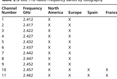
Reception 34 Frequency 37 Bandwidth 40 WLAN Frequency Bands 41 Modulation 42
Phase Modulation 44
Communicating with Wireless LAN Technologies 48
Microwave Technology 48
Infrared Technology 49
Spread Spectrum Technology 50 Synchronization 52
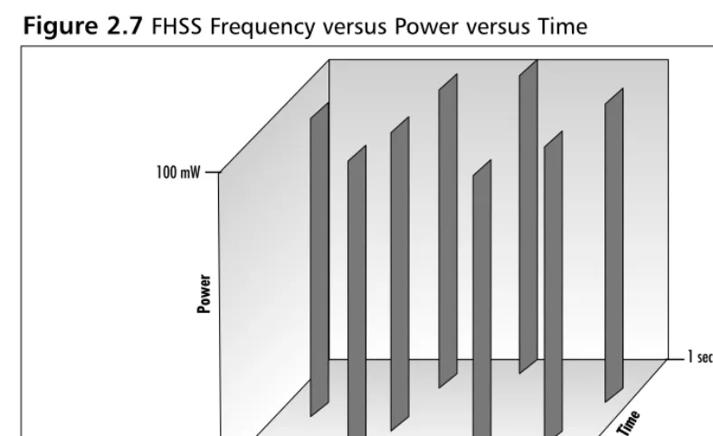
Frequency Hopping 52
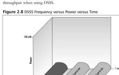
Direct Sequence Spread Spectrum (DSSS) 53
DSSS Channel Setup 54
Spectrum Technology Comparisons: Frequency Hopping versus Direct
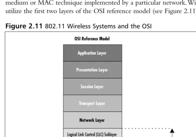
Sequence 55 Implementing a Wireless LAN Architecture 55 The OSI Reference Model 56 Logical Wireless System Components 59 Distribution System 59 Medium Access Technique 59 Synchronization and Error Control 60
Routing Mechanisms 60
Application Interface 60 Physical Wireless System Components 60 Medium 60
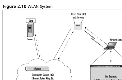
Access Point (AP) 60
Antenna 61
Wireless Station 61
Server 61
Phase Modulation
The following modulation techniques are used in Cisco Aironet radios: ■ Binary Phase Shift
Keying (BPSK)
■ Quadrature Phase Shift Keying (QPSK)
Keeping Pace with Wireless Networking
Standards 61
Institute of Electrical and Electronic
Engineers (IEEE) 62
802.11 66 802.11b 77 802.11a 79 Other Related Working Groups 80 European Telecommunications
Standards Institute (ETSI) 81 Wireless Ethernet Compatibility
Alliance (WECA) 86
WLAN Interoperability Forum (WLIF) 87 Infrared Data Association 87 Summary 88
Solutions Fast Track 89
Frequently Asked Questions 91
Chapter 3 Cisco Wireless LAN
Product Line 93
Introduction 94 Overview of Cisco Wireless Systems 95 Cisco’s WLAN Product Line 95 Using WLANs for Individual User
Connectivity 96 Using WLANs to Connect Campuses 97 Cisco’s Aironet 3X0 Series APs and Bridges 99 The Cisco Aironet 350 Series 99
Features Common to All 350
Series Devices 99
Individual 350 Series Device Features 103 Features of the Cisco Aironet 340 Series 110 Individual 340 Series Device Features 110 Cisco’s Aironet Wireless NICs 115 Cisco Aironet Antennas 117 Ceiling Mount Omni-Directional Antenna 120 Mast Mount Omni-Directional Antenna 120
Answers to Your Frequently Asked Questions
Q: How far can a wireless client communicate to an Access Point (AP)? A: Client adapters can
High-Gain Mast Mount Omni-Directional
Antenna 120 Pillar Mount Diversity Omni-Directional
Antenna 121 POS Diversity Dipole Omni-Directional
Antenna 121 Diversity Ceiling Mount Omni-Directional
Patch Antenna 121
Directional Wall Mount Patch Antenna 122 Diversity Directional Wall Mount Patch
Antenna 122
Yagi Antenna 123
Dish Antenna 123
Summary 125
Solutions Fast Track 127
Frequently Asked Questions 129
Chapter 4 Wireless Network Design 131
Introduction 132 Wireless Planning Considerations 132 Wireless Benefits and Limitations 134
What Type of Data Will Be
Traversing the Wireless Network? 134 How Much Data Will Be
Traversing the Wireless Network? 135 What Is the Return On Investment
for Your Wireless Implementation? 136 How Does Mobility Factor into
Determining if Wireless Is Right
for Your Business? 136 Does Your Business or Corporation
Have Any Restrictions That Would Prohibit You from Implementing a
Wireless LAN Solution? 137 Mobility 138 Throughput versus Data Rate and Load 139 Cost and Return on Investment 141
Designing & Planning…
Calculating the Fresnel Zone
A bit of mathematics is required to calculate the size of the Fresnel zone radius at its widest point (midpoint radius). The following formula will allow you to calculate the radius in feet of the widest point in your Fresnel zone:
Fresnel Zone Radius Formula
Wireless Design Considerations 143 Attenuation 143 Attenuation Due to Antenna Cabling 144 Attenuation Due to Exterior
Considerations 144 Accounting for the Fresnel Zone and
Earth Bulge 149
Radio Frequency Interference 150 Interference from Radio Transmitters 151 Harmonics 152 Application Considerations 152 Structural Considerations 153 Andromeda Manufacturing Rough Design 156
Wireless Design 1 157
Wireless Design 2 157
Performing a Wireless Site Survey 158 Preparation 159 Sample Pre-Site Survey Form 160 Other Preparations 162 Infrastructure Awareness 166
What Types of Network Media
Are Used? 166
What Operating Systems,
Protocols, and Drivers Are Used? 168 What Hubs Are Used? 168 What Switches Are Used? 168 What Routers Are Used? 169 What Bridges Are Used? 169 How Is Power Supplied? 170 Preparing a Site Survey Kit 170 Using Client Adapters in the Survey 171 Using APs and Bridges in the Survey 172 Choosing Antennas for the Survey 173 Providing Battery Packs and Inverters
for the Survey 174
Bringing Temporary Mounting
Equipment for the Survey 178 Performing an Interior Wireless Site Survey 180 Designing for Coverage 181 Designing Seamless Roaming 183 Considering Rate Shifting 184 Performing the Interior Survey 184 Using the Cisco Aironet Client
Utility for Interior Site Surveys 186 Watching Your Power Consumption 190 Setting Your Service Set IDs 191 Interior Survey Problems 191 Performing an Exterior Wireless Site Survey 193 Wireless Design Examples 195 Warehouse Design Example 1 196 Warehouse Design Example 2 197 Warehouse Design Example 3 198 Retail Design Example 198 Education Design Example 1 199 Education Design Example 2 200 Point-to-Point Design Example 1 201 Point-to-Point Design Example 2 201 Point-to-Point Design Example 3 203 Summary 204
Solutions Fast Track 205
Frequently Asked Questions 206
Chapter 5 Installation and Configuration of Cisco 340 and Cisco 350 Series
Access Points 209
Introduction 210 Installation of the Cisco 340/350 Series AP 213
Specific Differences of the Cisco 350
Series AP 215
Power Requirements 216
Network Connectivity 217
Initial Configuration of the Cisco 340 and
350 Series AP 219
IP Setup Utility 220
Terminal Emulator Setup 221 Web-Based Configuration of the Cisco 340
and 350 Series APs 223
Configuring the Cisco 340 and
350 Series APs 223
Configuring the Web Interface 224 Configuring a Name Server 224 The Radio Hardware Setting 224 The AP Radio Port Status Screen 227
Setting the Time 227
User Accounts 228
Setting the WEP Key 229
Accounting Setup 232
Hot Standby 233
Publicly Secure Packet Forwarding 233 Troubleshooting the Cisco 340 and
350 Series APs 234
Web-Based Configuration of the Cisco 340
BSE/BSM Series AP 241
Configuring the Cisco 340 BSE/BSM
Series AP 242
Troubleshooting the Cisco 340
BSE/BSM Series AP 246
Summary 247
Solutions Fast Track 248
Frequently Asked Questions 249
Chapter 6 Installation and Configuration
of Cisco Aironet Bridges 253
Introduction 254 Understanding the Role of
Traditional Network Bridges 254 Types of Network Bridges 256
Comparing Traditional Bridges with Wireless Bridges
Cisco Aironet 340 and 350 wireless bridges can be used in one of three modes:
■ Wireless bridge between two wired network segments (point-to-point) ■ Wireless bridge
between three or more wired network
segments (point-to-multipoint)
Comparing Traditional Bridges with
Wireless Bridges 259
Cisco Aironet Wireless Bridge—
Point to Point 260
Cisco Aironet Wireless Bridge—
Point-to-Multipoint 261 Cisco Wireless Bridge—Repeater 261 Installation of the Cisco Aironet Bridge Unit 262 Installing the Antenna 263 DSSS (Direct Sequence Spread Spectrum) 263 Configuring the Network Port 265 Configuring the Console Port 266
Applying Power 267
Working with Root and Non-Root
Modes on a Wireless Bridge 267 Overview of the Spanning Tree Protocol 269 Initial Setup of the Cisco Aironet Wireless Bridge 273
Configuring the Bridge Using
the Command-Line Interface 273 Configuring the Bridge Using the
Command Menus 273
General Configuration Recommendations
and Notes 275
Performing the Initial Configuration 275 Assigning the Radio Parameters 276 Assigning IP Information 277 Operational Configuration of the
Cisco Aironet Wireless Bridge 279
Console Access 279
Telnet Access 279
Web Browser Access 280
Using the Cisco Aironet Wireless Bridge
Radio Main Menu 281
Configuring the LinkTests Options 288 Configuring the Extended Options 288 Configuring the Ethernet Port 292 Configuring the Network Identifiers 292 Console Management Access 294 Configuring Passwords 294 Configuring Privileges 295
SNMP Support 295
Configuring the Time Service 296 Setting Up Association Tables 297
Using Filters 300
Configuring the Multicast Option 300 Configuring the Node Option 301 Configuring the Protocols Option 302
Event Logging 303
Viewing Statistics 305
Throughput Option 306
Radio Option 306
Ethernet Option 307
Status Option 308
Map Option 308
Watch Option 308
History Option 308
Node Option 308
ARP Option 309
Display Time Option 309
Ipadr Option 309
Cisco Aironet Wireless Bridge Troubleshooting 309
Network Menu Option 310
Connect Option 310
Escape Option 310
Find Option 311
Ping Option 311
Linktest Menu Options 311
Restart Option 314
Loading Firmware and Configurations 314 Xmodem and Crc-xmodem 315 FTP—File Transfer Protocol 315 Distribute 317
BOOTP and DHCP 318
Class 318 Backing Up Wireless Bridge Configurations 318 Summary 320
Solutions Fast Track 323
Frequently Asked Questions 327
Chapter 7 Installation and Configuration
of Cisco Wireless Network Cards 329
Introduction 330 Cisco Aironet Client Adapter Types 331
Comparing the Cisco Aironet 340 and
350 Series Wireless LAN Adapters 331 Cisco Aironet Client Utility (ACU) 333
Installing and Configuring the
Cisco Aironet LAN Adapter Card 334 Installing the Cisco ACU 335 Cisco Aironet Client Profile Manager 336 Creating a New Aironet Client Profile 337 Using an Existing Aironet Client Profile 337 Modifying an Existing Aironet Client
Profile 338 Reconfiguring Profiles with the
Default Aironet Client Profile Values 338 Renaming Profiles Stored within
the ACU 338
Deleting Profiles Stored within
the ACU 338
Importing Profiles to the ACU 338 Exporting Profiles from the ACU 339 Restricting Profile Access to
Administrative Users 339
Client Adapter Auto Installer
A DOS-based configuration file encryption utility is provided for the safeguard of the INI or TXT
configuration file. The utility encrypts the file by using a scrambling algorithm that can be decrypted by the Auto Installer. The utility is called EncryptIni.exe: 1. Select Start | Run. 2. In the Open prompt,
type Commandand press Enter.
3. Using the DOS
commands, navigate to the directory where the EncryptIni.exe and the configuration files are located.
Cisco Aironet Client Installation and
Configuration 340 Configuring the Cisco Aironet
Client System Parameter 341 Setting the Client Name 341
Setting the SSID 341
Setting Power Save Mode 342 Setting the Network Type 342 Cisco Aironet Client RF Network
Configuration 343 Configuring the Data Rate 344 Choosing Radio Headers 345 Setting World Mode 345 Selecting the Power Level 345 Setting the Data Retries Value 346 Selecting Maximum Packet Size 346 Configuring the Cisco Aironet
Client: Advanced (Infrastructure) 346 Antenna Mode (Receive)/Antenna
Mode (Transmit) 347
Specified AP 348
RTS Threshold 348
RTS Retry Limit 348
Cisco Aironet Client Advanced Ad Hoc
Configuration 348 Antenna Mode (Receive)/Antenna
Mode (Transmit) 349
RTS Threshold 350
RTS Retry Limit 350
Wake Duration (Kms) 350 Beacon Period (Kms) 351 Cisco Aironet Client Network Security
Using the Auto Installer 354 Installation Configuration File Field
Definition 354 Client Adapter Diagnostics 357 Configuring ACU Diagnostics Preferences 357 Displaying the Current Status 358 Displaying the Operational Statistics 358 Displaying the Link Status Meter 361 Signal Strength Indicator 362 Signal Quality Indicator 362 Signal Status Line 362 Performing a Radio Frequency Link Test 362 Client Adapter Indicator LEDs 364 LED Display Patterns 364 Summary 367
Solutions Fast Track 369
Frequently Asked Questions 372
Chapter 8 Cisco Wireless Security 375
Introduction 376 Understanding Security Fundamentals
and Principles of Protection 377 Ensuring Confidentiality 377
Ensuring Integrity 379
Ensuring Availability 380
Ensuring Privacy 381
Ensuring Authentication 381 Extensible Authentication Protocol (EAP) 385 An Introduction to the 802.1x Standard 389 Per-Packet Authentication 392 Cisco Light Extensible
Authentication Protocol (LEAP) 393 Configuration and Deployment of LEAP 395 Ensuring Authorization 396
MAC Filtering 398
What Is a MAC Address? 398
Designing & Planning…
Preventing Dictionary Attacks Using EAP
EAP was designed to sup-port extended authentica-tion. When you implement EAP, you can avoid dic-tionary attacks by using nonpassword-based schemes such as biomet-rics, certificates, OTP, smart cards, and token cards.
Where in the Authentication/Association
Process Does MAC Filtering Occur? 399 Determining MAC Filtering Is Enabled 400
MAC Spoofing 400
Ensuring Non-Repudiation 401 Accounting and Audit Trails 404
Using Encryption 405
Encrypting Voice Data 406 Encrypting Data Systems 407 Reviewing the Role of Policy 407 Identifying Resources 409 Understanding Classification Criteria 411
Implementing Policy 412
Addressing the Issues with Policy 415
Implementing WEP 417
Defining WEP 417
Creating Privacy with WEP 418 The WEP Authentication Process 419 WEP Benefits and Advantages 419
WEP Disadvantages 420
The Security Implications of Using WEP 420 Implementing WEP on the Cisco
Aironet AP 340 420
Exploiting WEP 421
Security of 64-Bit versus 128-Bit Keys 422
Acquiring a WEP Key 422
Addressing Common Risks and Threats 423
Finding a Target 424
Finding Weaknesses in a Target 424 Exploiting Those Weaknesses 426 Sniffing, Interception, and Eavesdropping 427
Defining Sniffing 427
Sample Sniffing Tools 427 Sniffing Case Scenario 428 Protecting Against Sniffing and
Spoofing and Unauthorized Access 430
Defining Spoofing 430
Sample Spoofing Tools 431 Protecting Against Spoofing
and Unauthorized Attacks 432 Network Hijacking and Modification 432
Defining Hijacking 432
Sample Hijacking Tools 434 Hijacking Case Scenario 434 Protection against Network
Hijacking and Modification 434 Denial of Service and Flooding Attacks 435 Defining DoS and Flooding 435
Sample DoS Tools 436
DoS and Flooding Case Scenario 436 Protecting Against DoS and Flooding Attacks 437 Summary 438
Solutions Fast Track 439
Frequently Asked Questions 444
Chapter 9 Cisco Aironet Accessories 447
Introduction 448
Antenna Accessories 449
Yagi Articulating Mount 449
Magnetic Mount 450
Lightning Arrestor with Grounding Ring 450 Bridge and Access Point Accessories 452
Bridge Mounting Kit 452
Bridge Slide Mount Kit 454 Access Point / Bridge Spare Power Supplies 457 Access Point / Bridge Serial Cable 458
NEMA Enclosures 460
Cabling, Connectors, and Bulkhead Extenders 462 Cabling 463 RG-58 and RG-8 Cabling 464
9913 Cabling 464
Connectors 467
RP-TNC Connectors 467
Bulkhead Extenders 468
Radio Country Options 469
Summary 472
Solutions Fast Track 473
Frequently Asked Questions 475
Over the last 10 years, the impact of wireless communications on the way we live and do business has been surpassed only by the impact of the Internet. Cellular phones, pagers, and wireless personal digital assistants (PDAs) have become so com-monplace in our lives that it is easy to forget that 10 years ago, they were a rarity. But wireless communications technology is still in its infancy, and the next stage of its development will be in supplementing or replacing the network infrastructure that was traditionally “wired” as well as enabling network infrastructures that previously could only be imagined. From local coffee shops to commercial inventory control systems, within restaurants and throughout public airports, wireless commerce is beginning to challenge the exchange system that our modern world currently embraces, by accessing central pools of information and communicating directly between users and between the devices themselves.
No longer are our choices restricted by the shortfalls of processing and battery power, operating system efficiencies, or heat dissipation within the small footprint of the mobile device. Rather, we are limited only by the practical application of these technologies. How will we access information? How will we integrate multiple hard-ware and softhard-ware technologies into intelligent and useable form factors? Not all business models necessarily imply the use of a single terminal to supply the user with voice, video, and data services. Ergonomic factors may dictate that voice services are maintained privately while data exchange and video information is easily viewable from a specified distance, perhaps on complementary devices.
As network engineers, the challenges before us include the seamless distribution of information between seemingly incompatible software and hardware standards. In addition, we will be challenged by narrower bandwidths to develop highly efficient means of transport in order to fully leverage wireless technologies.
Wireless LAN (Wi-Fi) technology is a reliable and convenient method of pro-viding immediate, highly flexible, and pedestrian-speed mobile data network access.
IEEE 802.11-based products offered by Cisco Systems have quickly become one of the foundational technologies fostering the untethering of data communications in the same way cordless telephony enhances local mobility for residential voice com-munications.
Wi-Fi, however, is significantly more complex than cordless telephony; loss, cov-erage, and bandwidth requirements are much more stringent, not to mention that direct sequence spread-spectrum (DSSS) is inherently more complicated than fre-quency division multiple access (FDMA) and time division multiple access (TDMA). More important, the proliferation of wireless LANs in corporate environments has resulted in interesting security challenges.
Many organizations do not invoke IEEE security features. In addition, the current IEEE 802.11 standard authentication techniques of using Service Set Identifiers (SSID) and Media Access Control (MAC) addressing do not provide strong authenti-cation. And although Wired Equivalent Protocol (WEP) combines access control, data privacy, and data integrity using an underlying algorithm, it can also be broken via passive monitoring with freely available monitoring software such as AirSnort. Fortunately, Cisco offers enhanced capabilities to mitigate some weaknesses. Of course, proper design and implementation are critically important; the design should exclude direct wireless access point connectivity to the internal network, strong secu-rity mechanisms must be implemented at different levels, and strict secusecu-rity policies must be enforced.With 802.11b access speed ranging from 1 Mbps up to 11 Mbps, and distances reaching from 500 feet indoors to as much as 5 kilometers outdoors, a wireless LAN could offer an unwanted user powerful network access.
Connectivity, availability, and capacity issues are resolved with proper frequency planning and testing. Security concerns are properly addressed with unobtrusive testing, implementation of proper policies, and firewalls. Network addressing must also be implemented consistently.
Callisma regularly assists customers with these considerations.This book will edu-cate readers on some of the theory and practical information required to successfully and safely deploy Wi-Fi.
—Ralph Troupe
Introduction to
Wireless Local
Area Networks
Solutions in this chapter:
■ Reviewing Networking Basics
■ Understanding How Wireless Fits into the
OSI System Model
■ Reviewing TCP/IP Basics
Chapter 1
1
; Summary
; Solutions Fast Track
Introduction
Wireless local area networks (WLANs) can be employed to provide network connectivity almost anywhere. Consider the cost savings from not having to run network cable to every possible location that could have a computer or network device connected to it. Consider the convenience of a wireless-enabled confer-ence room. Imagine the increase in accuracy of a medical professional’s data entered directly into a tablet computer during his rounds through the WLAN instead of transcribed from a clipboard at a central workstation. Conference rooms, warehouses, indoor and outdoor public access areas, and hospitals are all suitable locations for WLANs. Unfettered access to the network, regardless of physical location, or traditional cable distance limitations is one of the primary drivers for WLANs.
Where can you fit WLANs into your existing infrastructure? Just about any-where you like.WLANs allow network designers to no longer be constrained by the 100m distance limitation for Category 5 copper cabling. Because WLANs use radio frequency (RF) signals to communicate, users can stay connected to the network almost anywhere.
Many companies are merging WLANs into their traditional wired networks to provide connectivity to the network to large numbers of users. Conference rooms are a great place to start considering wireless in your network.The cost of wiring a conference room and maintaining the hardware required to keep those wired jacks “hot” can be prohibitive. Conference rooms are used for “chalk talk” design sessions, application development sessions, and training. By using WLANs, the need for multiple data jacks in a conference room can be eliminated. A single antenna connected to a WLAN access point (AP) can support many users.
Warehouse applications are also prime candidates for WLAN. Real-time inven-tory control can be implemented using wireless. Imagine having your inveninven-tory control software connected to mobile devices on the warehouse floor tracking inventory as it fluctuates during the course of a day.WLANs can be a very impor-tant business driver, enabling a company to gain a competitive advantage.
Hospital bedside access is also a popular application for WLANs.The ability for a hospital staff member to check in a patient at bedside rather than waiting in line at an admissions desk is much more efficient. Bedside access can also enable a doctor to write a prescription or check medical records on a patient instantaneously.
the user to just her desk, or even in the building, to be productive. For the growing mobile workforce, wireless provides the connectivity.
Reviewing Networking Basics
Before we delve into the topic of WLANs, we need to cover networking in gen-eral. A network is defined as a series of points or nodes interconnected by commu-nication paths.The points or nodes may be devices dedicated to a single function, such as a PC dedicated to client applications, or a router dedicated to intercon-necting networks.This chapter covers some fundamental theories, technologies, and applications for networks. LAN Technologies such as Ethernet, Fast Ethernet, Gigabit Ethernet,Token Ring, and Fiber Distributed Data Interface (FDDI) are prevalent in the networking industry today.
There are three primary types of networks, the local area network (LAN), metropolitan area network (MAN), and the wide area network (WAN).The dis-tinguishing feature of these networks is the spatial distance covered. LANs, as the name implies, are typically contained in a single structure or small geographic region. Groups of LANs interconnected may also be referred to as a campus in larger environments. MANs connect points or nodes in a geographic region larger than a LAN, but smaller than a WAN. Some of the same LAN technologies may be employed in a MAN, such as Gigabit Ethernet.WANs are geographically diverse networks and typically use technologies different from LANs or MANs. WANs typically are comprised of high-speed circuits leased from a telecommuni-cations provider to facilitate connectivity.WANs rarely use the same technologies as LANs or MANs.Technologies such as Frame Relay, Integrated Services Digital Network (ISDN), X.25, Asynchronous Transfer Mode (ATM), Digital Subscriber Line (DSL) and others may be used.This is because of the larger distances WANs service.
Defining Topologies
N
OTEThe word topologycan refer to either the physical or logical layout of the network. For example, an Ethernet network with a hub would have a star topology, but the logical topology would be a bus.
Bus Topology
A bus topology is a linear LAN architecture in which transmissions from network devices or stations propagate the entire length of the medium and are received by all nodes on the medium. A common example of a bus topology is
Ethernet/IEEE 802.3 networks, as illustrated in Figure 1.1.
Star Topology
A star topology is a LAN architecture in which the devices or stations on a net-work are connected to a central communications device, such as a hub or switch. Logical bus and ring topologies are often physically implemented in star topolo-gies. Figure 1.2 shows a typical star topology.
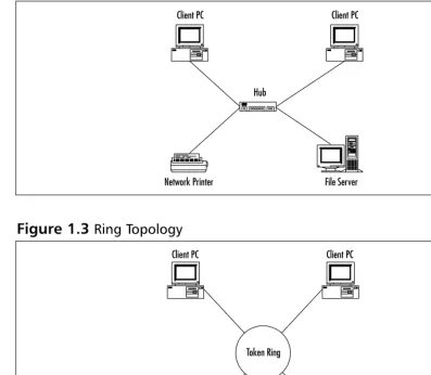
Ring Topology
A ring topology is a LAN architecture in which the devices or stations on a net-work are connected to each other by unidirectional transmission links to form a single closed loop. Common examples of ring topologies are Token Ring/IEEE 802.5 and FDDI networks, as illustrated in Figure 1.3.
Figure 1.1Bus Topology
Ethernet
File Server Network Printer
Mesh Topology
A mesh topology is a LAN architecture is which every device or station on a network is connected to every other device or station. Mesh topologies are expensive to deploy and cumbersome to manage because the number of connec-tions in the network can grow exponentially.The formula used to calculate the number of connections in a fully meshed network is as follows:
(N x (N–1))/2
where N is the number of devices on the network. Divide the result by 2 to avoid double counting the device A-to-device-B connection and the device
Figure 1.2Star Topology
File Server Network Printer
Client PC Client PC
[image:32.612.73.470.95.441.2]Hub
Figure 1.3Ring Topology
Token Ring
File Server Network Printer
B-to-device-A connection.To illustrate the large numbers that a fully meshed environment can reach, review the following examples:
■ A small network with 50 users wants to implement a fully meshed
topology.The number of connections required to do this would be (50 ×(50–1))/2, which equals 1,225.That is a lot of connections for a small LAN!
■ A medium network with 500 users wants to implement a fully meshed
topology.The number of connections required to do this would be (500 ×(500–1))/2 which equals 124,750 connections!
Now for the reality check on fully meshed networks. Fully meshed networks are typically implemented in a small handful of situations.The most common deployment model for fully meshed networks would be in the WAN arena. Frame Relay and ATM are technologies that are well suited for fully meshed networks with high availability requirements. Figure 1.4 depicts a typical mesh network.
CSMA/CD versus Deterministic Access
In LANs, there are two predominant methods of controlling access to the physical medium: Carrier Sense Multiple Access with Collision Detection (CMSA/CD) and deterministic access. CSMA/CD is the access method for Ethernet.
CSMA/CD is best described as the same set of rules you would follow in a meeting. In a meeting, everyone in the room has the right to speak, but everyone follows the generally accepted rule of “Only one person can talk at one time.” If
Figure 1.4Mesh Topology
File Server Network Printer
you want to speak, you need to listen to see if anyone is else is speaking before you begin. If someone else is speaking, you must wait until they are finished before you can begin. If nobody is speaking, you can speak, but will continue to listen in case someone else decides to speak at the same time. If they do, both speakers must stop talking, wait a random amount of time, and start the process again. If a speaker fails to observe the protocol of only one speaker at a time, the meeting will quickly lose all effective communication. (Sounds too familiar, doesn’t it?)
In Ethernet, the multiple access (MA) is the terminology for many stations connected to the same cable and having the opportunity to transmit. No device or station on the cable has any priority over any other device or station. All devices or stations on the cable do take turns communicating per the access algo-rithm to ensure that one device on the LAN does not monopolize the media.
The CS (carrier sense) refers to the process of listening before speaking in an Ethernet network.The carrier sense operation is performed by every device on the network by looking for energy on the media, the electrical carrier. If a carrier exists, the cable is in use, and the device must wait to transmit. Many Ethernet devices maintain a deferral or back-off counter defining the maximum number of attempts the device will make to transmit on the cable. If the deferral counter is exceeded, typically 15 attempts, the frame is discarded.
The CD (collision detect) in Ethernet refers to the capability of the devices on the wire to know when a collision occurs. Collisions in Ethernet happen when two devices transmit data at the same time on the cable. Collisions may be caused by the cable distance being exceeded, a defective device, or a poorly written driver that does not adhere to Ethernet specifications.When a collision is detected, the participants generate a collision enforcement signal.The enforce-ment signal lasts as long as the smallest Ethernet frame size, 64 bytes.This sizing ensures that all stations know about the collision and do not attempt to transmit during a collision event. After the collision enforcement signal has finished, the medium is again open to communications via the carrier sense protocol.
Deterministic access is the protocol used to control access to the physical medium in a token ring or FDDI network. Deterministic access means that a control system is in place to ensure that each device on the network has an equal opportunity to transmit.
Cabling
to the foundation of a building. Everything in the building is set upon the foun-dation, typically strong reinforced concrete or other equally durable and reliable building materials. If the foundation is not installed properly, everything built on this foundation is suspect. A LAN is the same, a faulty foundation can be disas-trous to a network.You can install all of the high-end gear, switches, routers, servers, but if they don’t have the physical infrastructure to communicate effec-tively, your network will fail.
There are two primary forms of physical medium a network will utilize: copper and fiber. Between these two forms, there are sometimes many different standards of cable. For example, copper may be shielded, unshielded, twisted, untwisted, solid core, or braided core.We explore copper and fiber cable in more detail to provide a solid understanding of the importance of cabling in your net-work.You may be asking yourself “Why are we covering cabling in a book on wireless?”That is a very good question.Wireless, as its name implies, does not use physical cabling to provide communications to the wireless network. However, it does use copper cabling to connect to your existingLAN. If your existing LAN has out-of-spec or faulty cabling, your WLAN may not meet your expectations. (Or more importantly, your boss’s expectations!)
The most common form of LAN cabling installed today is copper. Copper has been the “preferred” installation since networks starting taking hold in the corporate world in 1980 when Xerox developed Ethernet. Copper is relatively cheap, easy to install, and can meet most distances that LANs were designed to cover.The original Ethernet specification used what is called thick coaxial cable. This cable lived up to its name for sure! Thick coax is much bigger than the tra-ditional copper cable you might be familiar with. After thick coax came thin coax.Thin coax was a cheaper and easier to handle and install cable alternative. Both of these cable types are implemented in a bus topology. As we covered ear-lier, a bus topology is linear LAN architecture. Each device or station on a bus is connected to the same medium. One of the major downsides to thick and thin coax was that it created a single point of failure. If the bus were to experience a failure or cut, the network became nonfunctioning.
cables—plays a role in protecting the cable from this interference.Twisted pair cables are less prone to interference than flat, or nontwisted cables.
Among the twisted pair cabling family are a number of different levels of cables.These are commonly referred to as categories, or CAT for short.The pri-mary differences between the categories is the number of twists per foot in the cable. More twists per foot equals less susceptibility to outside interference. Some of the newer, higher categories of cabling also have internal dividers intertwined with the copper cabling to further reduce interference.These higher standards allow faster communications such as Fast Ethernet at 100 Mbps and Gigabit Ethernet at 1000 Mbs over copper cabling.
Understanding How Wireless
Fits into the OSI System Model
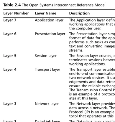
Wireless technology, as a networking component, is guided by the same standards processes and organizations defined for all other networking components in the industry. Although working in the networking industry can be difficult at best, there are many components to a network that can either make or break the system. In order to help standardize and define the areas a manufacturer must build their equipment to service, the International Organization for Standard-ization (ISO) created the Open Systems Interconnection (OSI) reference model. This model is a seven-layer approach to data networking. Each layer encompasses
The Blame Game
When planning your WLAN implementation, you need to consider the wired network and its physical plant. Connecting a WLAN to a wired net-work with a questionable physical plant is a plan for trouble. Troubleshooting connectivity to a new technology is difficult enough because the new technology is the first to be blamed. On man occa-sions, problems have been blamed on the wireless network when in fact the wired network and the wiring itself was to blame. Approximately 60 percent of all network problems can be tracked to the physical layer. Don’t let your wired network create havoc in your wireless network.
a specific set of tasks or standards that must be met in order for the network to function.We’ll review each layer in greater detail because this is a very important concept to understand. A comprehensive understanding of the OSI system model is of paramount importance for the internetworking designer, installer, or support team.
The seven layers to the OSI system model are as follows:
■ Physical layer ■ Data-link layer ■ Network layer ■ Transport layer ■ Session layer ■ Presentation layer ■ Application layer
We start at the bottom with the Physical layer.The Physical layer of the OSI system model is responsible for defining the electrical and mechanical aspects of networking.Topics such as cabling and the methods for placing the 0’s and 1’s of binary data on the medium are covered in great detail here. Standards such as Category 5, RS-232, and coaxial cable fall within the realm of the Physical layer.
The next layer is the Data-link layer.The Data-link layer defines the protocols that control the Physical layer. Issues such as how the medium is accessed and shared, how devices or stations on the medium are addressed, and how data is framed before transmission on the medium are defined here. Common examples of Data-link layer protocols are Ethernet,Token Ring, FDDI, and PPP.
or contention (CSMA/CD). Figure 1.5 shows an example of MAC addresses “on the wire” after being passed from the MAC layer to the Physical layer and being converted to 0’s and 1’s.
The next sublayer is the LLC layer.The LLC sublayer is responsible for han-dling error control, flow control, framing, and MAC sublayer addressing.The most common LLC protocol is IEEE 802.2, which defines connectionless and connection-oriented variants. IEEE 802.2 defines Service Access Points (SAPs) through a field in the Ethernet,Token Ring, or FDDI frame.Two SAPs are asso-ciated with LLC: the Destination Service Access Point (DSAP) and the Source Service Access Point (SSAP).These SAPs in conjunction with the MAC address can uniquely identify the recipient of a frame.Typically LLC is used for protocols such as SNA that do not have a corresponding network layer.
The next layer defined by the OSI reference model is the Network layer.The Network layer is responsible for addressing a network above the Data-link layer. The Network layer is where protocols such as Transmission Control
Protocol/Internet Protocol (TCP/IP), Internetwork Packet Exchange (IPX) and AppleTalk tie into the grand scheme of things. Routing functions are also per-formed at the Network layer.TCP/IP routing protocols such as Routing Information Protocol (RIP), Open Shortest Path First (OSPF), and the Border Gateway Protocol (BGP) operate at the Network layer.We focus more on TCP/IP in the upcoming “Review of TCP/IP Basics” section.
The three previous layers we covered, Physical, Data-link, and Network, are considered the lower level protocols in the OSI reference model.These are the protocols that will more than likely consume the majority of your time as a
Figure 1.5MAC Layer to Physical Layer
Ethernet
PC #1 PC #2
Data from PC#1
000000000110000010001100101110100011100100110111 to PC #2
network engineer. However, that does not mean that the next four layers are not important to the operation of a network.They are equally important, because without the next four layers, your network doesn’t even need to be in existence.
The fourth layer of the OSI system model is the Transport layer.The Transport layer defines the protocols that control the Network layer, similar to the way the Data-link layer controls the Physical layer.The Transport layer speci-fies a higher level of flow control, error detection, and correction. Protocols such as TCP, User Datagram Protocol (UDP), Sequenced Packet Exchange (SPX), and Name Binding Protocol (NBP) operate at this layer.These protocols may be con-nection-oriented, such as TCP and SPX, or connectionless, such as UDP.
The fifth layer of the OSI system model is the Session layer.The Session layer is responsible for establishing, managing, and terminating communication sessions between Presentation layer entities and the Transport layer, where needed.
Lightweight Directory Access Protocol (LDAP) and Remote Procedure Call (RPC) are examples of Session layer protocols.
The sixth layer of the OSI system model is the Presentation layer.The Presentation layer is responsible for ensuring that data sent from the Application layer of one device is comprehensible by the Application layer of another device. IBM’s Network Basic Input Output System (NetBIOS) and Novell’s NetWare Core Protocol (NCP) are examples of Presentation layer protocols.The ISO also developed a Presentation layer protocol named Abstract Syntax Notation One (ASN.1), which describes data types independent of various computer structures and representation techniques. ASN.1 was at one time thought to be the
Presentation layer protocol of choice, when the ISO’s protocol stack was going to sweep the networking industry. Now we know that some components of ISO, such as Intermediate System to Intermediate System (IS-IS) as a routing protocol, and the X.500 directory services protocol have been widely deployed, while the majority of the protocol stack has been neglected.
Tracking Data through the OSI System Model
Understanding how data moves across an internetwork is a very important com-ponent of being a network engineer.You need a comprehensive grasp of the technologies and the standards they support, and you also need to know how those technologies and standards relate to the actual network.The OSI system model bridges that gap for you. Knowing the details of the network as well as the way end-user applications interact with the network is a powerful trouble-shooting tool.
One of the easiest analogies used to understand the OSI system model is that of sending a letter through the mail. A number of items must be completed for your letter to be delivered to the appropriate recipient.We walk a letter through the postal system and illustrate the parallel connections to the OSI system model.
The first thing that you need to do to send a letter is to write it.You sit down at your desk and write a letter to your friend that lives on the other side of the country. After you finish writing the letter, you get an envelope and address it to your friend.You then walk to your mailbox and place the letter inside.These actions correlate to the OSI system model layers nicely.Writing the letter corre-sponds roughly to the Application layer. If you used a word processor to write the letter, then print it out to place in the envelope, the act of printing the letter would be similar to what happens at the Application layer.The fact that you printed the letter means that you relinquished control of the letter to the net-work, the postal system in this case.Your actual words on the paper correspond to the Presentation layer in that you needed to ensure that the recipient, your
Now that the envelope is in the network, the postal system, it may pass through many different offices. If you view these offices as nodes on a network, they would correspond to routers.The envelope reaches your local post office, or default gateway in a TCP/IP network, and is scanned by a computer to deter-mine if the envelope requires routing for proper delivery. In this example, your friend lives across the country, so the envelope does need to be routed.The com-puters in the post office review the destination address and determine the best path for the envelope to take to reach its final destination.The next office, or hop, on the path the envelope takes may be a regional office or some other cen-tral location with routes to the next hop.Your envelope is transported by mail truck, plane, or other form of transportation.The actual path and transmission medium are unimportant to you as you relinquished control of your letter when you placed it in your mailbox.You are trusting that the postal service will ensure that your letter arrives.
Your envelope finally reaches the local post office for your friend.The enve-lope is delivered to your friend and is opened.Your friend opens the enveenve-lope, pulls out the letter, and reads it.These last steps correlate to the OSI system model working in reverse.The data, your letter, is de-encapsulated when the envelope is opened.The contents are then delivered to the recipient when your friend reads the letter, a mapping to the Presentation layer, and comprehends through the Application layer.
OSI and Wireless: Layer 2 and Down
Now that you have an understanding of the OSI system model, we can relate the different technologies used in WLANs to the OSI system model. As the name wire-less LANimplies, it is networking without wires.The wires you are accustomed to using are replaced by radio signals. A number of various techniques are available for sending data over radio signals—these are covered in greater detail in Chapter 2.
The standards covered by the Cisco WLAN products detailed in this book are based on the IEEE’s 802.11 series.The 802.11 standards are responsible for defining the Physical and MAC layers of operation in a WLAN.The primary standard we focus on in the 802.11b standard, which is an extension to the original 802.11 standard. 802.11b’s primary objective defines the use of the 2.4 GHz band in radio frequency (RF) for high-speed data communications. 802.11b supports the original 802.11 data rate of 2 Mbps as well as higher speeds up to 11 Mbps.
aspects of the WLAN.We first examine a typical 802.2 Ethernet frame and com-pare it to a 802.11b frame.
An 802.2 Ethernet frame is comprised of six fields each with a specific func-tion. Figure 1.6 illustrates an Ethernet frame.
■ Preamble The first field in an Ethernet frame is the preamble.The
preamble is an 8-byte long alternating pattern of 0’s and 1’s telling receiving devices that a new frame is arriving.
■ Destination Address and Source Address The next fields are the
destination address (DA) and source address (SA).The fields are 2 or 6 bytes long and contain the MAC address of the source device on the network and the destination address.The destination address may be a single MAC address in the case of a unicast, a broadcast to all nodes on the network, or a multicast to a group of nodes on the network.
■ Length The next field is the length and is 2 bytes long describing the
number of bytes of data following this field.
■ Data Unit The next field is the data unit containing the user data of
the frame and is 46–1500 bytes long.This is where the data being encapsulated into the frame is located; for example the graphic in a Web page requested by your system.This field will vary in length based on the data encapsulated.
■ Frame Check Sequence The last field in an Ethernet frame is the
Frame Check Sequence (FCS) field and is 4 bytes long.The FCS is a cyclic redundancy check (CRC) on the frame allowing the receiver of the frame to perform basic error controls on the frame. If a frame fails the CRC check, it is discarded and the upper layer protocol is typically responsible for retransmission.
Figure 1.6Ethernet Frame Format
P DA SA L DU FCS
A 802.11b frame (illustrated in Figure 1.7) is comprised of nine fields.
■ The first field in an 802.11b frame is the frame control(FC) field and is 2
bytes long.The FC field contains ten subfields including protocol ver-sion, type, subtype, to Distribution System (DS), from DS, more frag-ments, retry, power management, more data,Wired Equivalent Protocol (WEP), and order.These fields are some of the prime differentiators in an 802.11b frame and are described in greater detail here:
■ Protocol Version The protocol version field is the first field within
the frame control field and is 2 bits long.The default value for this field is 0 with all other values being reserved at this time.
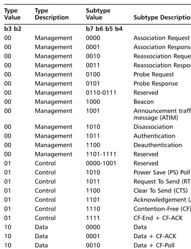
■ Type The type field is 2 bits long and works in conjunction with
the 4-bit subtype field to identify the function of the frame.The pos-sible combinations and their descriptions are illustrated in Table 1.1.
■ To Distribution System The To DS field is 1 bit long and is set
to 1 in all frames sent by an associated station with an AP to signify that the frame is destined for the network behind the AP, such as a server connected to the same Ethernet network as the AP. All other frames have the To DS bit set to 0.
■ From Distribution System The From DS field is 1 bit long and
is set to 1 on all frames exiting the DS. All other frames have the From DS bit set to 0.
■ More Fragments The More Fragments (MF) field is 1 bit long and
is set to 1 in all frames that contain another fragment of the current MAC Service Data Unit (MSDU) or MAC Management Protocol Data Unit (MMPDU). All other frames have the MF bit set to 0.
Figure 1.7802.11b Frame Format
A2
FC = Frame Control 2 bytes D/ID = Duration/ID 2 bytes A1 = Address 1 6 bytes A2 = Address 2 6 bytes A3 = Address 3 6 bytes SC = Sequence Control 2 bytes A4 = Address 4 6 bytes FB = Frame Body 0–2312 bytes FCS = Frame Check Sequence 4 bytes
■ Retry The retry field is 1 bit long and is set to 1 in all frames, data
or management, that are retransmissions of earlier frames. Frames that are not retransmissions of a previous frame are set to 0.
■ Power Management The Power Management (PM) field is 1 bit
long and is used to indicate the power management mode of a sta-tion.The value is used to indicate the state in which the station will be in after the successful completion of the frame exchange sequence. A value of 1 is used to indicate that the station will be in power-save mode, whereas 0 indicates that the station is in active mode.
N
OTEThe PM field in frames transmitted by a wireless Access Point will always be set to 0, indicating active mode. It would not be desirable for an AP on your network to go into power-save mode.
■ More Data The More Data field (MD) is 1 bit long and used to
tell an associated station in power-save mode that one or more frames are buffered for the station on the AP.The MD field is set to 0 for all other directed frames.
■ WEP The WEP field is 1 bit long and is set to 1 if the frame body
contains data that has been processed by the WEP algorithm. Frames that have not been processed by WEP have a WEP field value of 0.
■ Order The Order field is 1 bit long and is set to 1 in any data
frame that contains data using the StrictlyOrdered service class. All other frames have a value of 0 in the Order field.
N
OTETable 1.1802.11 Type and Subtype Combinations in the Frame Control (FC) Field
Type Type Subtype
Value Description Value Subtype Description b3 b2 b7 b6 b5 b4
00 Management 0000 Association Request
00 Management 0001 Association Response
00 Management 0010 Reassociation Request
00 Management 0011 Reassociation Response
00 Management 0100 Probe Request
00 Management 0101 Probe Response
00 Management 0110-0111 Reserved
00 Management 1000 Beacon
00 Management 1001 Announcement traffic indication
message (ATIM)
00 Management 1010 Disassociation
00 Management 1011 Authentication
00 Management 1100 Deauthentication
00 Management 1101-1111 Reserved
01 Control 0000-1001 Reserved
01 Control 1010 Power Save (PS) Poll
01 Control 1011 Request To Send (RTS)
01 Control 1100 Clear To Send (CTS)
01 Control 1101 Acknowledgement (ACK)
01 Control 1110 Contention-Free (CF) End
01 Control 1111 CF-End + CF-ACK
10 Data 0000 Data
10 Data 0001 Data + CF-ACK
10 Data 0010 Data + CF-Poll
10 Data 0011 Data + CF-ACK + CF-Poll
10 Data 0100 Null function (no data)
10 Data 0101 CF-ACK (no data)
10 Data 0110 CF-Poll (no data)
10 Data 1000-1111 Reserved
11 Reserved 0000-1111 Reserved
■ The next field in an 802.11b frame is the Duration/ID field and is 16
bits long. It is used to carry the association ID of a station with an Access Point.
■ The next fields in the 802.11b frames are address fields. If you review an
Ethernet frame, you see that there are only two fields for addresses: desti-nation and source. In 802.11b frames, there may be up to four, the basic service set identifier (BSSID), destination address (DA), source address (SA), receiver address (RA), and transmitter address (TA).
■ The BSSID is the MAC address of the Access Point. ■ The DA is the MAC address of the final recipient.
■ The SA is the MAC address of the sending station on the WLAN. ■ The RA is the MAC address of the intended immediate recipient
stations on the WLAN.
■ The TA is the MAC address of the sending station on the WLAN. ■ The next field in an 802.11b frame is the frame body and is 0–2312 bytes
long.The frame body is the payload, or data contained within the frame. This is where the data being encapsulated into the frame is located, for example the graphic in a Web page requested by your system.This field will vary in length based on the data encapsulated.
■ The final field in the 802.11b frame format, just as in the Ethernet
format, is the FCS.
As you can see, there are a number of differences between Ethernet and 802.11b frames.These differences are required to enable high-speed communica-tions on a physical medium of radio waves rather than standard copper or fiber media.
Table 1.1Continued
Type Type Subtype
OSI and Wireless: Layer 3 and Up
The OSI system model applies to the configuration, management, and trouble-shooting of Cisco WLANs far beyond Layers 1 and 2. Certainly Layers 1 and 2 are key to WLANs, but the other layers play key roles as well. For example, all configuration of wireless APs and bridges are done through Telnet and HTTP, two Application-layer protocols.The Web interface on APs and bridges use HTTP in their graphical interfaces.This is a key topic to understand because if there is a problem accessing the Web interface, you need to be able to use your knowledge of the OSI system model to troubleshoot the problem. Could the problem be caused by an access list on a router between your system and the AP, is it a problem with general network connectivity, can you ping the AP’s TCP/IP address? These all come into play in determining the cause of the failure.
Bridges and APs also use other protocols in the OSI system model. Examples include the following:
■ Dynamic Host Configuration Protocol (DHCP) at Layer 7 to
automati-cally obtain a TCP/IP address on the network from a DHCP server.
■ Extensible Authentication Protocol (EAP) at Layer 7 working with
RADIUS.
■ Remote Authentication Dial In User Service (RADIUS) at Layer 7 in
conjunction with EAP to authenticate WLAN users.
■ WEP at Layer 2 to encrypt/decrypt data on the WLAN.
Review of TCP/IP Basics
TCP/IP was originally implemented as a standard protocol for the pre-fledging Internet called ARPANET for the United States government Advanced Research Projects Agency, which funded the network. As the ARPANET grew, the need to have a standardized protocol became apparent. IP as a protocol was defined in Request for Comments (RFC) 760 in 1980;TCP was defined in RFC 793 in 1981.TCP/IP comprises a suite of protocols.This means that many different protocols fall under the umbrella of TCP/IP.
A few of the more common TCP/IP protocols include HTTP, File Transfer Protocol (FTP), SMTP, Internet Control Message Protocol (ICMP), and Post Office Protocol (POP). Each of these protocols uses IP as their base foundation for moving data on a network. Looking at TCP/IP from the perspective of the OSI system model can be very beneficial to understand how the protocols inter-relate. For example, SMTP, a messaging protocol is defined as an Application layer protocol, and as such, resides at Layer 7 of the OSI system model. SMTP relies on TCP at the Transport layer to establish a reliable connection to a remote system. TCP in turn relies on IP to provide addressing information and routing capabili-ties to ensure that the data is sent to the proper destination.We cover TCP in more depth later in the chapter.
Understanding TCP/IP Addressing
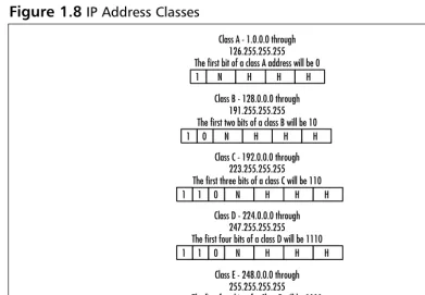
IP addresses are divided into five distinct classes, with three of the classes being predominant.The classes are labeled by the alphabet, so the classes are A, B, C, D, and E. Figure 1.8 illustrates the different classes.
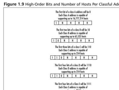
As you can see, each class of address allows for a varying number of hosts. For example, in each class A address, there is the possibility of 16,777,214 hosts, while a class C address has the possibility of 254 hosts.The class of address employed in an organization usually depends on the number of devices to be addressed.
To determine the class of address you are dealing with, there are two primary mechanisms. One, the simplest, is memorization; the other is to examine the high order, or first bits of the IP address.The high-order bits will always dictate the class of address space used without fail, whereas memorization is susceptible to human error. In Figure 1.9, you can see the high-order bits and the number of addresses possible per class.
One of the more difficult tasks for a TCP/IP network administrator is that of
[image:49.612.59.451.123.394.2]subnetting.TCP/IP addresses can be broken down into smaller networks called subnets. Subnetting can be very beneficial because it allows for effective address allocation and broadcast domain control. Subnets are created by the network
Figure 1.8IP Address Classes
N
1 H H H
Class A - 1.0.0.0 through 126.255.255.255 The first bit of a class A address will be 0
N
1 H H H
Class B - 128.0.0.0 through 191.255.255.255 The first two bits of a class B will be 10
0
N
1 0 H H H
Class C - 192.0.0.0 through 223.255.255.255 The first three bits of a class C will be 110 1
N
1 0 H H H
1
Class D - 224.0.0.0 through 247.255.255.255 The first four bits of a class D will be 1110
N
1 0 H H H
1
Class E - 248.0.0.0 through 255.255.255.255 The first four bits of a Class E will be 1111 1