-Service Manual TANDY 6000/6000-HD
TANDY COMPUTER PRODUCTS
-7.6 Power Supply Board
7.6.1 Functional Specifications
The Power Supply Assembly for the Tandy 6000/6000HD is a 140 watt switching power supply. The Printed Circuit
Board is mounted to the electronic chassis bracket. Line input to the power supply module is made through an amp wafer with locking 3-pin socket header.
Pin 1 Line - Neutral Pin 2 Blank
Pin 3 Line - High
Outputs are taken from an amp wafer with locking 15-pin PCB socket header.
Pin 1 -12 V Pin 9 +5 V
Pin 2 -12 V Pin 10 Common
Pin 3 Common Pin 11 +5 V
Pin 4 Common Pin 12 +5 V
Pin 5 Common Pin 13 +24 V
Pin 6 Common Pin 14 +12 V
Pin 7 Common Pin 15 +12 V
Pin 8 +5 V
In theory, the power supply rectifies the AC line to DC, then chops it at 20 kHz. The chopped DC voltage is then transformed to the required output voltages and rectified to low voltage isolated DC. Feedback loops are provided for voltage regulation and over-current protection.
The power supply may be jumper selected for either of the following ratings:
Vin 90 to 135 VAC @ 47 to 63 Hz input frequency or 190 to 270 VAC @ 47 to 63 Hz input frequency The Power Supply Assembly can withstand the following maximum ratings:
Vin (AC continuous) or
Service Manual TANDY 6000/6000-HD
_ _ _ _ _ _ _ _ _ _ _ TANDY CDMPUTER PRDDUCTS
-Min Typ Max
Output Voltages VOl 4.95 5.00 5.25 V V02 11.40 12.00 12.60 V V03 See Notes
V04 21.60 24.00 26.40 V V05 -11.40 -12.00 -12.60 V
V04, no load tolerance
Note: 1) V03 must not change from its initial value by more than + 100 millivolts under the following load conditions on the V04 output.
a) A step increase in output current from O.OA (initial condition) to 2.5A Max. decaying to 0.92A total within 350 msec.
b) A step increase in output current from 0.55A (initial condition) to 3.05A Max. decaying to 1.45A total within 350 msec.
2) The V03 output may vary
+
5% under all other conditions of rated line, load, and temperature.Min Typ Max
Output Loads 101 3.0 4.3 13.36 A 102 0.25 0.50
103 0.10 1.0
104 0 1.3
105 0.05 0.1
Min Typ OCP, Current Limit
ICLI 14.0 15.0 ICL2 1.1 1.6 ICL3 1.6 2.3 ICL4 2.1 2.5
ICL5 1.0
Note: VOS is a thermally protected IC
OVP r Crowbar VCBl
Output Noise VOl V02 V03 V04
Min Typ
5.94 6.25
0.75 A 1.5 A 2.0 A 0.2 A
Max Units
16.0 A 2.0 A 3.0 A 3.0 A 2.0 A
regulator.
Max
7.00 V
50 mV p-p 100 mV p-p 100 mV p-p 250 mV p-p
-Service Manual TANDY 6000/6000-HD
TANDY CDMPUTER PRDDUCTS
-Hold Up Time:
Full Load Lo Line Full Load Nom Line
Insulation Resistance Input to Output Input to Ground Output to Ground
Isolation
Input to GND and Output
Min
10 16
100 100 100
4.25
Typ Max
18 mSec
30 mSec
1000 M ohm
1000 M ohm
1000 M ohm
KVDC
Service Manual TANDY 6000/6000-HD
_ _ _ _ _ _ _ _ _ _ TANDY COMPUTER PRODUCTS
-7.6.2. Equipment for Test Set-up
1. Isolation Transformer (minimum of 500 VA rating) CAUTION
Dangerously high voltages are present in this power supply. For the safety of the individual doing the testing, please use an isolation
transformer. The 500 VA rating is needed to keep the AC waveform from being clipped off at the peaks. These power supplies have peak charging capacitors and draw full power at the peak of the AC waveform.
2. 0-140 V Variable Transformer (Variac) -- used to vary the input voltage. Recommend 10 amp, 1.4 KVA rating, minimum.
3. Voltmeter Need to measure DC voltages to 50 VDC and AC voltages to 200 VAC. Recommend two digital
multimeters.
4. Oscilloscope Need XIO and Xl probes.
5. Load board with connectors See Table 7-5 for values of loads required. The entry on the table for Safe Load Power is the minimum power ratings for the load
resistors used.
Note: Because of its design, this power supply must have a load present or damaging oscillations may result. Never test the power supply without at least the minimum load shown in Table 7-5. 6. Ohmmeter
7.6.3 Set-Up Procedure
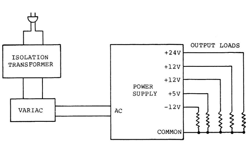
1. Set up as shown in Figure 7-15. You will want to
monitor the input voltage and the output voltage of the regulated bus, which is the +5 V output, with DVMs.
Also monitor the +5 V output with the oscilloscope using 50 mV/div sensitivity. The DVM monitoring the +5 V
-Service Manual TANDY 6000/6000-HD
TANDY COMPUTER PRODUCTS
-=============================================================
Output Min Load R for Min Max Load R for Max J2
Amps Load Amps Load Pins
=============================================================
+5V VOl 3.0 1.66 ohm 13.36 .34 ohm 8,9,
30 W 130 W 11,12
+12 V02 .25 48 ohm .75 16 ohm 15
6
w
20w
+12 V03 .10 120 ohm 1.5 8 ohm 14
4 W 40 W
+24 V04 0 Infinity 2.0 12 ohm 13
100 W
-12 V05 .05 2.4 ohm .2 60 ohm 1,2
1 W 5 W
Table 7-9. Power Supply Voltage Chart
OUTPUT LOADS ISOLATION
TRANSFORMER
VARIAC AC
POWER SUPPLY
+24V +12V +12V +5V -12V
~
~
>
I
~1
~
COMMON
Figure 7-15. Test Layout, Power Supply
~~
"
:~~
~
~~
~
[image:5.615.84.512.333.579.2]Service Manual TANDY 6000/6000-HD
_ _ _ _ _ _ _ _ _ _ _ TANDY COMPUTER PRODUCTS
-2. Visual Inspection
Check power supply for any broken, burned, or obviously damaged components. Visually check the fuse. If any questions, check with an ohmmeter.
3. Start-up
Load power supply with m1n1mum load as specified in Table 7-5. Bring up power slowly with the variable transformer while monitoring the +5 V output with the oscilloscope and DVM. The power supply should start with approximately 40-60 volts applied, and should regulate when 95 VAC is reached. If the output has
reached 5 volts, complete a performance test as shown in Section 7.3.5. If there is no output, refer to Section 7.3.4.
4. Bracket Removal
The main PCB is held to the bracket with screws and uses spacers to separate the PCB from the bracket. An
insulator is inserted between the PCB and the mounting bracket to ensure that the bracket cannot short any of the pins of the PCB.
7.6.4. No Output 1. Check Fuse
If a fuse is blown, replace it but do not apply power until the cause of the failure is found.
2. Preliminary Check on Major Primary Components
Check diode bridge (DB1), power transistor (Q7), and catch diode (Q7) for shorted junctions. If any
component is found shorted, replace it.
3. Preliminary Check of Major Secondary Components Use an ohmmeter to check for shorted outputs on the various output lines. If the +5 V output is shorted, check also crowbar SCR (SCR1) and zener diode (Zl).
-Service Manual TANDY 6000/6000-HD
TANDY COMPUTER PRODUCTS
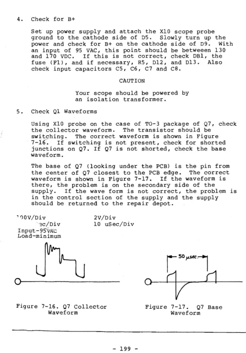
-4. Check for B+
Set up power supply and attach the
XIO
scope probe ground to the cathode side of D5. Slowly turn up the power and check for B+ on the cathode side of D9. With an input of 95 VAC, this point should be betweeen 130 and 170 VDC. If this is not correct, check DBl, the fuse (Fl), and if necessary, R5, D12, and D13. Also check input capacitors C5, C6, C7 andca.
CAUTION
Your scope should be powered by an isolation transformer.
5. Check Ql Waveforms
Using
XIO
probe on the case of TO-3 package of Q7, check the collector waveform. The transistor should beswi1:;s::hing. The correct waveform is shown in Figure
7-16.
If switching is not present, check for shorted junctions on Q7. If Q7 is not shorted, check the base waveform.The base of Q7 {looking under the PCB> is the pin from the center of Q7 closest to the PCB edge. The correct waveform is shown in Figure 7-17. If the waveform is there, the problem is on the secondary side of the
supply. If the wave form is not correct, the problem is in the control section of the supply and the supply
should be returned to the repair depot.
~00V/Div
fc/Div
Input-95'~AC
Load-minimum
2V/Div
10 uSec/Div
0---Figure 7-16. Q7 Collector
[image:7.619.50.530.73.760.2]Service Manual TANDY 6000/6000-HD
TANDY COMPUTER PRODUCTS
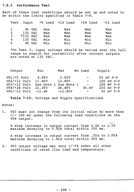
-7.6.5 Performance Test
Each or-these test conditions should be set up and noted to be within the limits specified in Table 7-9.
Test Input +5 Load +12 Load +24 Load -12 Load
1 95 VAC Max Max Max Max
2 135 VAC Max Max Max Max
3 *135 VAC Max Max Max Max
4 135 VAC Min Min Min Min
5 95 VAC Min Min Min Min
*On Test 3, input voltage should be varied over the full range to search for instability after correct outputs are noted at 135 VAC.
Output Min Max No Load Ripple
VOl/+5 Volt 4.90V 5.10V 50 mV p-p
V02/+12 Volt 11.40V 12.60V 100 mV p-p
V03/+12 Volt See Note 1 See Note 1 100 MV p-p
V04/+24 Volt 21.20V 26.40V 30.0V 250 mv p-p
V05/-12 Volt -11.40 -12.60V 50 mV p-p
Table 7-10. Voltage and Ripple Specifications Notes:
1. V03 must not change from its initial value by more than +/- 100 mV under the following load conditions on the V04 output.
A step increase in output current from O.DA.to 2.SA maximum decaying to 0.92A total within 350 ms.
A step increase in output current from .55A to 3.05A maximum decaying to 1.45A total within 350 ms.
[image:8.616.81.547.91.759.2]J
til
CD Ii
<:
1-'" ()
CD
ro5
s::
~Tl ::J
[C".1 ~
~
I-' c,'
(J
r,O
~
"0
0 AU -I
::J ~
CD
0
::J Z
rt D
-<
t"'1
n
~ O!
'<
D
0 ~tv 0
0 ~ 'tI
I-' rt c:
... -I
m
Ii.1 ]J
0 'tI
~
CD ]J
Ii 0
D
til c:
~
n
"0 -I
"0
rn
...
'<
(Xl
a·
1-3-...J :x:oo
\.0 Z
0 t:I
0 ...::
.&;:.
-...J CTI
0 0 0
"'"
CTIService Manual TANDY 6000/6000-HD
TANDY COMPUTER PRODUCTS
-Parts List, Power Supply 8790047 (Astec Components AAII082)
============================================================
Ref No. Description Mfr. Part No.
============================================================
Capacitors
Cl Capacitor, C2 Capacitor, C3 Capacitor, C4 Capacitor, C5 Capacitor, C6 Capacitor, C7 Capacitor, C8 Capacitor, C9 Capacitor, CIO Capacitor, Cll Capacitor, C12 Capacitor, C13 Capacitor, C14 Capacitor, C15 Capacitor, C16 Capacitor, C17 Capacitor, C18 Capacitor, C19 Capacitor, C20 Capacitor, C21 Capacitor, C22 Capacitor, C23 Capacitor, C24 Capacitor, C25 Capacitor, C26 Capacitor, C27 Capacitor, C28 Capacitor, C29 Capacitor, C30 Capacitor, C31 Capacitor, C32 Capacitor, C33 Capacitor, C34 Capacitor, C35 Capacitor, C36 Capacitor, C37 Capacitor, C38 Capacitor, C39 Capacitor,
Coils
0.1 uF, 0.22 uF, 2200 pF, 2200 pF, 220 uF, 220 uF, 220 uF, 220 uF, 0.01 uF, 2200 pF, 0.047 uF, 330 uF,
0.22 uF, 220 uF, 0.22 uF, 0.1 uF, 1000 pF, 0.01 uF, 470 uF, 470 uF, 470 uF, 2200 uF, 2200 uF, 2200 uF, 2200 uF, 100 uF, 0.22 uF, 1000 pF, 0.01 uF, 0.01 uF, 0.01 uF, 0.022 uF, 0.022 uF, 1000 uF, 100 uF, 1000 uF, 470 uF, 100 uF, 1000 pF,
2S0VAC, 20% 2S0VAC, 10% 400VAC, 20 %4) 400VAC, 20%
2S0V, +100/-10% 2S0V, +100/-10% 2S0V, +100/-10% 2S0V, +100/-10% 2S0VAC, 20%
SOV, 10% 2S0V, 10% 2SV, 20% 100V, 10 %
10V, 20% SxA 100V, 10% 100V, 10%
3KV, 20% Z5P 1KV, 20% ZSV 3SV, 20% SxA 25V, 20% SxA 25V, 20% SxA 25V, 20% SxA 25V, 20% SxA 25V, 20% SxA 25v I 20% SxA
25V, 20% SxA 100V, 10% 100V, 10% 100V, +80/-20 % 100V, +80/-20 % 100V, +80/-20% 100V, 20% 100V, 10%
35V, 20% SM 25V, 20% SxA 16V, 20% SxA 25V, 20% SxA 25V, 20% SxA 100V, 10%
-Service Manual TANDY 6000/6000-HD
_ _ _ _ _ _ _ _ _ _ TANDY COMPUTER PRODUCTS
-Parts List, Power Supply 8790047 (Astec Components AAII082)
============================================================
Ref No. Description Mfr. Part No.
============================================================ Coils L4 L5 L6 L7 Diodes Dl D2 D3 D4 D5 D6 D7 D8 D9 DI0 Dll D12 D13 D14 D15 D16 D17 D18 D19 D20 D21 D22 D23 D24 D25 D26 DBI Zl Fuses Fl F2 F3 F4 (con't>
Choke Coil Assy Choke Coil Assy
Filter Choke Coil Assy Filter Choke Coil Assy
Diode, Diode, Diode, Diode, Diode, Diode, Rectifier, Diode, Rectifier, Diode, Rectifier, Rectifier, Rectifier, Diode, Diode, Diode, Rectifier, Rectifier, Rectifier, Diode, Diode, Rectifier, Rectifier, Rectifier, Rectifier, Rectifier, 1N4606 1N4606 1N4606 1N4606 1N4606 1N4606 1N4001GP 1N4606 RGP10J 1N4606 1N4001GP RGP10J RGP10J 1N4606 1N4606 1N4606 S6K20 RG3B S6K20
SCK S10SC3M SCK S10SC3M RGP10B
1N4001GP 1N4001GP 1N4001GP 1N4001GP Bridge Rectifier, KBL08
Diode, Zener, 5.6V, 5%, 40mA
Service Manual TANDY 6000/6000-HD
_ _ _ _ _ _ _ _ _ _ TANDY COMPUTER PRODUCTS
-Parts List, Power Supply 8790047 (Astec Components AAll082)
============================================================
Ref No. Description Mfr. Part No.
======================================================:=====
Jumpers
Jl Jumper Wire, 12.7 mm 358-80800001
J2 Jumper Wire, 12.7 mm 358-80800001
J3 Jumper Wire, 12.7 mm 358-80800001
J4 Jumper Wire, 17 mm 358-80800001
J5 Jumper Wire, 17 mm 358-80800001
Integrated Circuits
ICl Regulator, LM317T 211-10300100
IC2 Regulator, MC7912 211-10300210
Resistors
Rl Thermistor, 4 ohm, 10% 258-40970015
R2 Thermistor, 4 ohm, 10% 258-40970015
R3 Resistor, lOOK ohm, 5% lW 248-10406052 R4 Resistor, lOOK ohm, 5% lW 248-10406052 R5 Resistor, 10 ohm, 5% l/4W 240-10006022 R6 Resistor, 470 ohm, 5% l/2W 240-47106033 R7 Resistor, 10 ohm, 5% 1/4W 240-10006022
R8 Resistor, lK ohm, 5% 1/4W 240-10206022
-R9 Resistor, 150 ohm, 5% 1/4W 240-15106022 RI0 Resistor, 100 ohm, 5% 1/4W 240-10106022 Rl1 Resistor, 470 ohm, 5% 1/4W 240-47106022 R12 Resistor, 470 ohm, 5% 1/4W 240-47106022 R13 Resistor, 220 ohm, 5% 1/4W 240-22106022 R14 Resistor, 27 ohm, 5% 5W, WW 257-27006120 R15 Resistor, 1K ohm, 5% 1/4W 240-10206022 R16 Resistor, 18 ohm, 5% 1/4W 240-18006022 R17 Resistor, 10 ohm, 5% 1/4W 240-10006022 R18 Resistor, 56 ohm, 5% 1/4W 240-56006022 R19 Resistor, 68 ohm, 5% 1/4W 240-68006022 R20 Resistor, 100 ohm, 5% 1/4W 240-10106022 R21 Resistor, 510 ohm, 5% 1/4W 257-51106120 R22 Resistor, 10 ohm, 5% 1/4W 240-10006022 R23 Resistor, 330 ohm, 5% 1/4W 240-33106022 R24 Resistor, .33 ohm, 5% 2W
Service Manual TANDY 6000/6000-HD
- - - TANDY COMPUTER PRODUCTS
Parts List, Power Supply 8790047 (Astec Components AA11082)
============================================================
Ref No. Description Mfr. Part No.
============================================================
Resistors (conlt>
R34 Resistor, 56 ohm, 5% 1/4W 240-56006022 R35 Resistor, 47 ohm, 5% 1/4W 240-47006022 R36 Resistor, 12K ohm, 5% 1/4W 240-12306022 R37 Resistor, 470 ohm, 5% 1/4W 240-47106022 R38 Resistor, 12 ohm, 5% 1/4W 240-12006022 R39 Resistor, 2.7K ohm, 2% 1/4W 247-27015022 R40 Resistor, 2.7K ohm, 2% 1/4W 247-27015022 R41 Resistor, lOOK ohm, 5% 1/4W 240-10406022 R42 Resistor, 68K ohm, 5% 1/4W
R43 Resistor, lOOK ohm, 5% 1/4W 240-10406022 R44 Resistor, 330 ohm, 5% 2W 248-33106063 R45 Resistor, 0.47 ohm, 5% 1w 247-04786054 R46 Resistor, 15K ohm, 5% 1/4W 240-15306022 R47 Resistor, 220 ohm, 2% 1/4W 247-22005022 R48 Resistor, 220K ohm, 5% 1/4W 240-22406022 R49 Resistor, 2.2K ohm, 1% 1/4W 247-22014022 Transformers
~ T1 T2 Transformer Assy Transformer Assy 852-10200680 852-10200680
T3 Transformer Assy, Power 852-10201300
Transistors
Q1 Transistor, NPN, SD467 209-11700460
Q2 Transistor, PNP, SB561 210-11700350
Q3 Transistor, PNP, SB561 210-11700350
Q4 Transistor, NPN, SD467 209-11700460
Q5 Transistor, PNP, SB561 210-11700350
Q6 Transistor, NPN, SD467 209-11700460
Q7 Transistor, NPN, 2SC1325A 209-10200040
Q8 Transistor, PNP, SB561 210-11700350
Q9 IC, TL431CLP 211-10800100
Miscellaneous
SCR1 SCR, C1 2u 227-13000010
Service Manual
-TANDY 6000/6000-HD
TANDY CDMPUTER PRDDUCTS
-KBLOS
FI TI OBI RI
3.5~~~4r~~~.~4~A~~I;L~1'·lr~----,_---r--;----~~--4
VDA~11'."'r+~-'2
J 22 ]2200 -tJE-1.3-j~
-,...,-- R2 '" '~20C~+iS7
1220 R3 lOOK R4.~ °t~
~ L. _I~~A. r-~---+---JV'OO~K~--~~---~~---__,rvvv- CI2 RI4
~4'--- 330
2200pf ~R7.'O.o. +
GNO.---4---~
115V.---4_ __ - j __ ~_;oSI----+t_-'
01 IN46 os
fg
IN4606 27.4.L3~1
De~
IN4606 RI7 10 09RGPIOJ R21 510 R45
'fi~
cle.47 .01
100001'
'---£'H.'a 2SCI325 A
010 ~
~
IN4606=~8 .~\ R22
10 RI9 " R23
, -
~
RIO~
IK 07 IN4001GP RIS
S04S~~
3]?t---t-'1~,l1.
...
~Lj~2
r
.11IN4606
ell 05
230Vo---j---~
.047 IN4606 Ie
L2 ~--~-+--~----~----4--4--~--~--~---t--~--~~~\4-~--4---~ RI3
220 ~ CI4 20 Oil IN400lGP \ \ \ \ \ \ \ \ \ \ \ \ \ \ r
I
017 S6K20
I~'
,~
I~
100~ 10 018I~
RG38DI9,S6K20
~
.01 10K£l£A5£D PQR PRODUCT IaN 2· 4·83 I tNfd
~ F4 2A
+ 24 V 1.7A
+ I. 023
470 IN400lGP ... C34
1000
lei
<; C20 ~17 ~~~
... C35
470
100
H--T--r-+---+---~+ 12V I.SA
F
15~"' 4 R47 R48 R20 22.024
~,1ll
R44 330
J,L F3,2A
+C21
I
_---1--+---~+12V I.OA
470 .-bL
;-~---t--~~r-~--t'~Lt--~~~F)2~r--t--1---~+5V 13.4A
I
~. ~. 030 i~ C24 " ' h F' 15A .C22 \ 220 ZI'V .01 10 ~20~ C23 \~25 R38020 2200 2200 12
SlOSC3M
t--+--M·~D"1-~~~--~~--~~~--r---~--~-t---~COM
~~
I
~. IN4001 ""'26 • + ~6 r--D~25f----r;,-Cf-2G-P---I r + ~:022 IN400lGP L~~
'---+-R-1GP~,0-B-+--4---~2C79I-~--... --l---l---<> -12V 0.2A
*R41,42,843ARE OIPADJUST RESISTOR
1...---MATERIAL
FINISH
UNLESS OTHERWIS£ SPECIFIED TOLERANCES .xx: ~ .010 .XXX = t.o05
ANGLES-:t.-HOLE OIA TOLERANCES
.014 - .260,. ::&&r' 251-.750. ::88f .751 - up. ~:8b~ DIMENSIONS ARE IN INCHES
AND APPLY AFTER PLATING
00 NOT SCALE THIS DRAWING NEXT ASSV
448
USfD ON DR.
DONALD R. BOOTH CHECK DESIGN DAT, 213/ DAT. '.:/'- ;;.-TITlE
SCHEMATIC-POWER SUPPI,; MODEL 12