This is a repository copy of
Bidirectional dc/dc power converters with current limitation
based on nonlinear control design
.
White Rose Research Online URL for this paper:
http://eprints.whiterose.ac.uk/130500/
Version: Accepted Version
Proceedings Paper:
Konstantopoulos, G. orcid.org/0000-0003-3339-6921 and Alexandridis, A. (2018)
Bidirectional dc/dc power converters with current limitation based on nonlinear control
design. In: 2018 26th Mediterranean Conference on Control and Automation (MED). The
26th Mediterranean Conference on Control and Automation, 19-22 Jun 2018, Zadar,
Croatia. IEEE , pp. 921-925.
10.1109/MED.2018.8442745
© 2018 IEEE. Personal use of this material is permitted. Permission from IEEE must be
obtained for all other users, including reprinting/ republishing this material for advertising or
promotional purposes, creating new collective works for resale or redistribution to servers
or lists, or reuse of any copyrighted components of this work in other works. Reproduced
in accordance with the publisher's self-archiving policy.
[email protected] https://eprints.whiterose.ac.uk/
Reuse
Items deposited in White Rose Research Online are protected by copyright, with all rights reserved unless indicated otherwise. They may be downloaded and/or printed for private study, or other acts as permitted by national copyright laws. The publisher or other rights holders may allow further reproduction and re-use of the full text version. This is indicated by the licence information on the White Rose Research Online record for the item.
Takedown
If you consider content in White Rose Research Online to be in breach of UK law, please notify us by
Bidirectional dc/dc power converters with current limitation based on
nonlinear control design
George C. Konstantopoulos and Antonio T. Alexandridis
Abstract— A new nonlinear controller for bidirectional dc/dc power converters that guarantees output voltage regulation with an inherent current limitation is proposed in this paper. In contrast to traditional single or cascaded PI controllers with a saturation unit that can lead to integrator windup and insta-bility, the proposed controller is based on a rigorous nonlinear mathematical analysis and, using Lyapunov stability theory, it is proven that the current of the converter is always limited without the need of additional saturation units or limiters. The proposed concept introduces a virtual resistance at the input of the converter and a controllable voltage that can take both positive and negative values leading to bidirectional power flow capability. The dynamics of this voltage are proven to remain bounded and with a suitable choice of the voltage bound and the virtual resistance, the upper limit for the converter current is guaranteed at all times, even during transients. Simulation results for a bidirectional converter equipped with the proposed controller are presented to verify the current-limiting capability and the desired voltage regulation.
I. INTRODUCTION
DC/DC power converters are known to convert a dc input voltage to a higher or lower level at their output and are widely used in renewable energy systems [1], [2], energy storage systems [3] and micro-grids [4], [5], [6]. Although for the cases of photovoltaic systems or dc loads, a unidirec-tional power flow is required, there are applications such as battery energy storage systems and electric vehicles where a bidirectional dc/dc converter is essential. Hence, the control design of these bidirectional converter applications has drawn a lot of attention recently due to the rising integration of storage systems to the power grid in order to guarantee a stable and reliable operation.
The operation of bidirectional dc/dc converters is based mainly on pulse-width modulation and considering a high switching frequency, the nonlinear average model of the converter can be obtained in order to design a suitable control method. The most widely used technique for regulating the voltage or current of a bidirectional dc/dc converter is using traditional single or cascaded PI controllers [7]. Based on linearization and the small-signal model of the converter, traditional PI controllers can be designed to guarantee local stability of the desired equilibrium point. However, the nonlinear dynamics of the converter dictate a need to design advanced control methods that can be applied directly to
This work was supported by the Innovate UK under Grant No. 103910. G. C. Konstantopoulos is with the Department of Automatic Control and Systems Engineering, The Univesity of Sheffield, Sheffield S1 3JD, U.K.
A. T. Alexandridis is with the Department of Electrical and Computer Engineering, University of Patras, Rion 26500, Greece.
the nonlinear model of the system, such as sliding control [8], [9], [10], [11] or passivity-based control [12], [13], [14], [15]. These advanced nonlinear control methods can guarantee nonlinear closed-loop system stability based on a strong mathematical theory but in most of the cases require the information of the system or load parameters that may vary depending on the application.
Although several nonlinear controllers have been recently designed for dc/dc converters to guarantee closed-loop sys-tem stability and convergence to a desired equilibrium based on Lyapunov theory [16], [17], [18], [19], an upper limit for the converter current cannot be guaranteed at all times, i.e. under changes of the load, input voltage or reference signal. Such a high current can be damaging for the converter in real applications. To overcome this crucial issue, traditional control methods introduce an inner current control loop with a saturation unit to limit the reference value of the current obtained by the outer loop [20]. However, as pointed out in [21], these saturated controllers introduce two main drawbacks: i) although the reference value of the converter current is limited, the actual value can violate the limit during transients and ii) saturated integrators can lead to integra-tor windup and instability. To this end, a current-limiting control method for different types of dc/dc converters was recently introduced in [21] to achieve accurate regulation and current limitation without any saturation units. The main disadvantage of this method is that it can be applied only to unidirectional dc/dc converters; hence it is not applicable to energy storage applications.
voltage regulation is accomplished under an inherent current protection of the converter, introduced by the proposed control design.
The rest of the paper is organized as follows. In Section II, the nonlinear dynamic model of the bidirectional dc/dc converter is presented and the desired problem is formulated. In Section III, the new current-limiting nonlinear control scheme is provided and the dynamics of the controller an analyzed. In addition, it is shown that under a suitable choice of the controller parameters, the current-limiting property of the converter is guaranteed independently from the direction of the power flow. In Section IV, simulation results illustrate the proposed controller performance and in Section V the conclusions of this work are drawn.
II. BIDIRECTIONAL DC/DC POWER CONVERTER MODEL
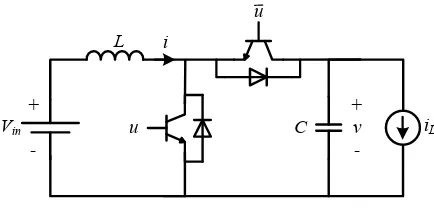
The bidirectional dc/dc converter shown in Fig. 1 consists of two switching elements, an inductor L at the input and a capacitor C at the output. The dc input voltage of the converter is represented as Vin, while the output current is denoted as iL, which can be positive or negative to represent a load or a source at the output of the converter, respectively. The converter is operated using pulse-width-modulation with a high switching frequency and the two switches are controller in a complementary manner, i.e. when uis closed then u¯ is open and vice versa. Under the common assumption of a high operating switching frequency and continuous conduction mode, using average theory, the continuous-time dynamic model of the bidirectional dc/dc converter can be obtained as shown below [12]:
Ldi
dt = −(1−u)v+Vin (1)
Cdv
dt = (1−u)i−iL (2)
whereiandv are the inductor current and capacitor voltage, respectively, and represent the system states while uis the control input representing the duty-ratio of the converter and is limited in the range[0,1]. Note that the dynamics of the bidirectional converter are nonlinear due to the termsuvand
ui, which make the control design and stability analysis a challenging task. Furthermore, when u= 1, it is clear from (1) that the inductor current will continuously increase and will reach high values that can cause damage to the converter. Hence, maintaining the inductor current i limited below a given maximum value is crucial in converter applications.
Although traditional control techniques introduce a cas-caded control structure (outer voltage controller and inner current controller) with saturation units, the current is not maintained limited during transients and saturation units can lead to instability. To this end, very recently, a current-limiting control for dc/dc converter was introduced without suffering from windup and instability to overcome these issues [21]. Nevertheless, this controller can be only applied to unidirectional dc/dc converters and does not allow bidirec-tional power flow; hence cannot be applied in energy storage systems and electric vehicles.
Vin +
-L
C iL
[image:3.612.326.543.48.152.2]+ -v i u u
Fig. 1. Bidirectional dc/dc power converter
III. PROPOSED CONTROL DESIGN AND ANALYSIS
A. The proposed controller
The main goal of this work is to design a controller that can be applied to bidirectional dc/dc converters to achieve output voltage regulation and a current-limiting capability without saturation units that can lead to instability. The proposed concept is based on the idea of partially decou-pling the inductor current dynamics, introducing a constant virtual resistance and a bounded controllable voltage. This bounded voltage will guarantee the desired upper limit for the converter current independently from the direction of the power flow (positive or negative current). Hence, the proposed controller takes the form:
u= 1−rvi+Vin−E
v , (3)
whererv>0represents a constant virtual resistance andEa
controllable voltage which introduces the following nonlinear dynamics:
˙
E=−k
E2
E2 m
+E2ql−1
E+cEq2l(vref −v) (4)
˙
Eq =−k
E2
E2 m
+E2ql−1
Eq−cEEq(vref −v)
E2 m
, (5)
whereEq is an additional control state,c,k,Em, are positive
constants, l ≥ 1 ∈ N and vref represents the desired
converter output voltage. To further understand the choice of the controller dynamics (4)-(5), let the following Lyapunov function candidate
W = E
2 E2 m +E 2l q
l . (6)
Taking the time derivative ofW and incorporating the control system (4)-(5), then
˙
W = 2EE˙
E2 m
+ 2E2l−1 q Eq˙
= −2k
E2 E2 m
+Eq2l−1
E2 E2 m
+2cEE
2l q E2
m
(vref −v)
−2k
E2 E2 m
+Eq2l−1
E2ql−
2cEE2l q E2
m
(vref −v)
= −2k
E2
E2 m
+E2l q −1
E2 E2 m
+E2l q
It is clear from (7) thatW˙ is negative outside the curve
W0=
E, Eq ∈R: E2 E2 m
+E2l q = 1
(8)
and positive inside except from the origin, where W˙ = 0. Therefore, for any initial conditionsE0andEq0except from
the origin, the controller state trajectory will be attracted on the curveW0. From (7), one can realize that the larger the
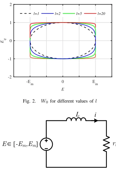
gaink, the faster the attraction on the curveW0. Forl= 1, W0represents an ellipse on theE−Eqplane while forl >1, W0 takes the form as depicted in Fig. 2.
Based on the Lyapunov analysis, since W˙ is negative outsideW0, then considering the setS={W(E, Eq)≤1},
i.e.
S=
(
E, Eq∈R: E2 E2 m
+E
2l q
l ≤1
)
,
then W <˙ 0 outside ofS since the curve W0 is contained
inside and on the boundaries ofS. This can be easily proven if one takes into account thatl≥1. Hence, every trajectory starting inside the setS will remain in the set for all future time. As a result, for any initial conditionsE0andEq0inside S, the controller states will satisfy
E2
(t)
E2 m
+E
2l q (t)
l ≤1,∀t≥0,
yielding
|E(t)| ≤Em,∀t≥0,
which results in a bounded voltageE below a given value
Emthat can be selected by the controller operator. Therefore,
E∈[−Em, Em] for allt≥0.
For an arbitrary large constant k, the controller states E
andEqare quickly attracted and remain close toW0resulting
in the dynamics
˙
E≈cE2l
q (vref −v) (9)
˙
Eq ≈ −cEEq(vref −v)
E2 m
. (10)
As it can be seen from Fig. 2, for a largel, the controller state Eq will be closer to the value 1 for the entire range ofE ∈[−Em, Em]. Hence, the dynamics ofEq are faster sinceEq˙ takes larger values in (5) compared to a case with a lower l. Then, the voltage dynamics (4) approximate the dynamics of the integrator
˙
E≈c(vref−v),
where c represents the integral gain (for more details the reader is referred to [22]). Hence, (4)-(5) represent bounded integral control dynamics without the need of a saturation unit that may lead to instability.
Considering (E0, Eq0)6= (0,0), the possible equilibrium
points of the controller dynamics are any points on the curve W0 that satisfy: i) v =vref, which corresponds the
the desired output voltage regulation or ii) (Ee, Eqe) = (±Em,0), corresponding to the case of current limitation as explained in the sequel.
-E
m 0 Em
E
-2 -1 0 1 2
Eq
l=1 l=2 l=5 l=20
Fig. 2. W0for different values ofl
L
r
vi
[image:4.612.337.528.55.333.2]E
[
-E
m,E
m]Fig. 3. Equivalent circuit of the closed-loop system
B. Current limitation
By applying the proposed controller expression (3) into the converter dynamics (1)-(2), the closed-loop system equation for the inductor currenti becomes
Ldi
dt =−rvi+E, (11)
and it is obvious that rv represents a virtual resistance in series with the converter inductorL.The equivalent circuit diagram of the closed-loop system is shown in Fig. 3.
In order to investigate how the selection of the virtual resistance and the bounded controller dynamics of E are related to the desired current-limiting property, let the Lya-punov function candidate
V = 1
2Li
2
for closed-loop current dynamics (11). The time derivative ofV yields
˙
V = Lidi
dt =−rvi 2
+Ei
≤ −rvi2+|E| |i| ≤ −rvi2+Em|i|,
given the bounded voltageE ∈[−Em, Em], which implies that
˙
V <0, ∀ |i|> Em rv .
Hence, if initially|i(0)| ≤ Em rv
, then it holds that
|i(t)| ≤ Em
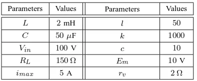
TABLE I
SYSTEM AND CONTROLLER PARAMETERS
Parameters Values Parameters Values
L 2mH l 50
C 50µF k 1000
Vin 100V c 10
RL 150 Ω Em 10V
imax 5A rv 2 Ω
due to the invariant set property. Based on the desired current-limiting property, it should hold true that
|i(t)| ≤imax,∀t≥0, (13)
for a given maximum value imax of the inductor current.
Then by combining (12) and (13), one can suitably select the parametersEmandrv in the proposed controller in order to
satisfy
Em=rvimax. (14)
Hence, any selection of the constant and positive parameters
Em and rv that satisfy (14) results in the desired
current-limiting property (13) of the converter inductor current inde-pendently from the load or system parameters (e.g. converter inductance, capacitance).
Note from the closed-loop dynamics (11) together with the controller dynamics (4)-(5) that when at the steady state there is v=ve=vref, thenE=Ee on the curveW0 and
the value of the inductor current becomes ie = Ee rv
. Since
Ee ∈ [−Em, Em], then the inductor current can be both positive and negative satisfying the bidirectional operation of the converter. WhenEe=Emthenie= Em
rv =imaxand when Ee=−Em thenie=−Em
rv =−imax corresponding to the current limitation of the converter in both directions of the current.
It should be underlined that opposed to the existing traditional current-limiting controllers, the proposed design maintains the current limited during transients, as proven by the nonlinear ISS property and does not require any external limiters or saturation units that can lead to instability, which highlights the superiority of the proposed controller.
IV. SIMULATION RESULTS
In order to validate the proposed controller performance and the current-limiting property of the converter, a bidi-rectional dc/dc power converter equipped with the proposed control scheme is considered and connected to a resistive load RL in parallel with a current source iL. The
cur-rent source can change from positive to negative values to enable the bidirectional operation of the converter. The system is simulated using the Simpower Systems toolbox of Matlab/Simulink based on the parameters given in Table I. Note that since the maximum current of the converter is imax = 5A, the controller parameters Em and rv are selected asEm= 10V andrv = 2 Ωto satisfy (14).
The desired task is to regulate the converter output voltage
v tovref = 200V independently from the variations of the
0 0.2 0.4 0.6 0.8 1 1.2 1.4 1.6
Time/s
100 120 140 160 180 200 220 240 260
v/V
(a) output voltage
0 0.2 0.4 0.6 0.8 1 1.2 1.4 1.6
Time/s
-2 0 2 4 6
i/A
i max
(b) inductor current
0 0.2 0.4 0.6 0.8 1 1.2 1.4 1.6
Time/s 0
0.2 0.4 0.6 0.8 1
u
(c) duty ratio
-12-10 -8 -6 -4 -2 0 2 4 6 8 10 12 E
-1.2 -1 -0.8 -0.6 -0.4 -0.2 0 0.2 0.4 0.6 0.8 1 1.2
E q
W 0
(d)E−Eq plane
[image:5.612.79.276.77.158.2]current source. Initially iL = 0.2A and as it can be seen from the simulations results in Fig. 4(a), the output voltage is quickly regulated at the desired level. Since the current of the load is positive, then the converter feeds the load and the inductor current is positive as well (Fig. 4(b)). In order to test the bidirectional operation of the converter under the proposed controller, att= 0.4s, the load currentiLchanges to −1.8A. In this case, the proposed controller regulates again the output voltage atvref after a short transient but as it is observed in Fig. 4(b), the inductor current is regulated at a negative value. At the time instant t = 0.8s, the load current iL becomes0.5A and the controller leads the converter output voltage at the desired level once again with a positive inductor current. In order to verify the current-limiting property of the controller, at t = 1.2s, the load currentiL changes to 1.5A. In this case, as shown in Fig.
4(b), the converter current reaches the upper limit (imax =
5A) and remains limited as analytically proven in this paper. The output voltage v automatically drops to a lower value to maintain the current-limiting property of the converter and hence protect the device from high load demands that request power levels that exceed the technical limits of the converter, as shown in 4(a). The transient response of the duty-ratio control input of the converter is illustrated in 4(c). To verify the theory presented in this paper, the trajectory of the controller statesEandEq is plotted on theE−Eq plane where it becomes clear that it remains very close to the curve
W0 at all times, proving the desired bounded dynamics of
the controller states.
V. CONCLUSIONS
A nonlinear dynamic control scheme was designed for bidirectional dc/dc converters to guarantee output voltage regulation with a current-limiting capability. By introducing a virtual resistance and bounded voltage dynamics, it was analytically proven that the inductor current of the converter will never violate a given maximum value. This current limitation is proven without any additional saturation units or limiters; hence overcoming integrator windup and instability problems that often occur with traditional current-limiting controllers. The effectiveness of the proposed design and its current-limiting property were verified by simulating a bidirectional converter under several changes of the load current.
Future work will focus on proving the asymptotic stability of the desired equilibrium of the bidirectional dc/dc converter and extend the proposed controller application to dc micro-grid systems with energy storage components.
REFERENCES
[1] G. C. Konstantopoulos and A. T. Alexandridis, “Non-linear voltage regulator design for DC/DC boost converters used in photovoltaic applications: analysis and experimental results,” IET Renewable Power
Generation, vol. 7, no. 3, pp. 296–308, 2013.
[2] S. K. Kim, J. H. Jeon, C. H. Cho, J. B. Ahn, and S. H. Kwon, “Dynamic modeling and control of a grid-connected hybrid generation system with versatile power transfer,” IEEE Transa. on Ind. Electron., vol. 55, no. 4, pp. 1677–1688, April 2008.
[3] Y. X. Wang, F. F. Qin, and Y. B. Kim, “Bidirectional DC-DC converter design and implementation for lithium-ion battery application,” in
2014 IEEE PES Asia-Pacific Power and Energy Engineering Con-ference (APPEEC), Dec 2014, pp. 1–5.
[4] M. Kabalan, P. Singh, and D. Niebur, “Large signal Lyapunov-based stability studies in microgrids: A review,” IEEE Transactions on Smart
Grid, to appear, early Access.
[5] J. A. Solsona, S. G. Jorge, and C. A. Busada, “Nonlinear control of a buck converter which feeds a constant power load,” IEEE Trans. on
Power Electron., vol. 30, no. 12, pp. 7193–7201, 2015.
[6] M. Car, M. Vasak, and V. Lesic, “Control of a buck-boost DC-DC power converter for microgrid energy storage,” in 19th International
Conference on Electrical Drives and Power Electronics (EDPE), Oct
2017, pp. 122–127.
[7] J.-H. Su, J.-J. Chen, and D.-S. Wu, “Learning feedback controller de-sign of switching converters via matlab/simulink,” IEEE Transactions
on Education, vol. 45, no. 4, pp. 307–315, 2002.
[8] S. Singh, D. Fulwani, and V. Kumar, “Robust sliding-mode control of dc/dc boost converter feeding a constant power load,” IET Power
Electronics, vol. 8, no. 7, pp. 1230–1237, 2015.
[9] Z. Chen, W. Gao, J. Hu, and X. Ye, “Closed-loop analysis and cascade control of a nonminimum phase boost converter,” IEEE Trans. Power
Electron., vol. 26, no. 4, pp. 1237–1252, 2011.
[10] J. A. Barrado, A. E. Aroudi, H. Valderrama-Blavi, J. Calvente, and L. Martinez-Salamero, “Analysis of a self-oscillating bidirectional DC-DC converter in battery energy storage applications,” IEEE Trans.
Power Del., vol. 27, no. 3, pp. 1292–1300, July 2012.
[11] L. Albiol-Tendillo, E. Vidal-Idiarte, J. Maixe-Altes, S. Mendez-Prince, and L. Martinez-Salamero, “Seamless sliding-mode control for bidirectional boost converter with output filter for electric vehicles applications,” IET Power Electronics, vol. 8, no. 9, pp. 1808–1816, 2015.
[12] R. Ortega, A. Loria, P. J. Nicklasson, and H. Sira-Ramirez,
Passivity-based Control of Euler-Lagrange Systems, Mechanical, Electrical and Electromechanical Applications. Springer-Verlag. Great Britain, 1998.
[13] R. Sira-Ramirez, H.and Silva-Ortigoza, Control Design Techniques in
Power Electronics Devices. Springer, London, 2006.
[14] H. Rodriguez, R. Ortega, G. Escobar, and N. Barabanov, “A robustly stable output feedback saturated controller for the boost dc-to-dc converter,” Systems & Control Letters, vol. 40, no. 1, pp. 1–8, 2000. [15] Y. I. Son and I. H. Kim, “Complementary PID controller to
passivity-based nonlinear control of boost converters with inductor resistance,”
IEEE Trans. Control Syst. Technol., vol. 20, no. 3, pp. 826–834, May
2012.
[16] Z. Wu and C.-H. Liu, “Nonlinear current-mode controller for DC/dc boost power converters,” Electronics Letters, vol. 47, no. 3, pp. 209– 211, 2011.
[17] K. F. Krommydas and A. T. Alexandridis, “Modular control design and stability analysis of isolated PV-source/battery-storage distributed generation systems,” IEEE Journal on Emerging and Selected Topics
in Circuits and Systems, vol. 5, no. 3, pp. 372–382, 2015.
[18] G. C. Konstantopoulos and A. T. Alexandridis, “Generalized nonlinear stabilizing controllers for Hamiltonian-passive systems with switching devices,” IEEE Trans. Control Syst. Technol., vol. 21, no. 4, pp. 1479– 1488, 2013.
[19] G. C. Konstantopoulos, Q.-C. Zhong, B. Ren, and M. Krstic, “Bounded integral control of input-to-state practically stable nonlinear systems to guarantee closed-loop stability,” IEEE Trans. Autom. Control, vol. 61, no. 12, pp. 4196–4202, Dec 2016.
[20] K. Saichand and J. Vinod, “Virtual resistance based control for ultracapacitor based bidirectional dc-dc backup system,” Department
of Electrical Engineering Indian Institute of Science, 2015.
[21] G. C. Konstantopoulos and Q. C. Zhong, “Current-limiting DC/DC power converters,” IEEE Trans. Contr. Syst. Technol., vol. PP, no. 99, pp. 1–9, 2018.