This is a repository copy of
Optically excited spin pumping mediating collective
magnetization dynamics in a spin valve structure
.
White Rose Research Online URL for this paper:
http://eprints.whiterose.ac.uk/135083/
Version: Published Version
Article:
Danilov, A. P., Scherbakov, A. V., Glavin, B. A. et al. (9 more authors) (2018) Optically
excited spin pumping mediating collective magnetization dynamics in a spin valve
structure. Physical Review B. 060302. ISSN 2469-9969
https://doi.org/10.1103/PhysRevB.98.060406
[email protected] https://eprints.whiterose.ac.uk/ Reuse
Items deposited in White Rose Research Online are protected by copyright, with all rights reserved unless indicated otherwise. They may be downloaded and/or printed for private study, or other acts as permitted by national copyright laws. The publisher or other rights holders may allow further reproduction and re-use of the full text version. This is indicated by the licence information on the White Rose Research Online record for the item.
Takedown
If you consider content in White Rose Research Online to be in breach of UK law, please notify us by
Rapid Communications Editors’ Suggestion
Optically excited spin pumping mediating collective magnetization
dynamics in a spin valve structure
A. P. Danilov,1A. V. Scherbakov,1,2B. A. Glavin,3T. L. Linnik,3A. M. Kalashnikova,2L. A. Shelukhin,2D. P. Pattnaik,4 A. W. Rushforth,4C. J. Love,5S. A. Cavill,5,6D. R. Yakovlev,1,2and M. Bayer1,2
1Experimentelle Physik 2, Technische Universität Dortmund, D-44227 Dortmund, Germany 2Ioffe Institute, 194021 St. Petersburg, Russia
3Department of Theoretical Physics, V. E. Lashkaryov Institute of Semiconductor Physics, 03028 Kyiv, Ukraine 4School of Physics and Astronomy, University of Nottingham, Nottingham NG7 2RD, United Kingdom
5Department of Physics, University of York, York YO10 5DD, United Kingdom 6Diamond Light Source Chilton, Didcot, Oxfordshire OX11 0DE, United Kingdom
(Received 22 May 2018; published 13 August 2018)
We demonstrate spin pumping, i.e., the generation of a pure spin current by precessing magnetization, without the application of microwave radiation commonly used in spin pumping experiments. We use femtosecond laser pulses to simultaneously launch the magnetization precession in each of two ferromagnetic layers of a galfenol-based spin valve and monitor the temporal evolution of the magnetizations. The spin currents generated by the precession cause a dynamic coupling of the two layers. This coupling has a dissipative character and is especially efficient when the precession frequencies in the two layers are in resonance, where coupled modes with strongly different decay rates are formed.
DOI:10.1103/PhysRevB.98.060406
The generation of a spin current by magnetization pre-cession is known as spin pumping (SP) [1]. Thereby, the precessing magnetization of a ferromagnetic (FM) film trans-fers angular momentum to an adjacent material, representing a pure spin current that is not accompanied by the flow of charges. Spin currents generated by SP contain an ac component at the precession frequency and carry also the magnetization precession phase. Conceptually, SP offers a new way of building spintronic devices by flexibly combining conducting and insulating materials [2–8]. This has stimulated intense efforts aimed at demonstrating spin currents in a robust way [9].
Conventional SP experiments exploit a ferromagnetic res-onance (FMR) where the magnetization precession is driven by a microwave field [10]. The transfer of angular momentum to the adjacent material results in enhanced damping of the FMR [11,12] and thus to a broadening of the corresponding resonance spectrum [13,14]. In turn, the spin current injected into the adjacent layer can be detected by, for example, the inverse spin Hall effect [2–8,15–22]. In a spin valve structure consisting of two FM layers separated by a nonmagnetic spacer, the spin current generated by one layer drives the mag-netization precession of the other layer [23–26]. At resonance, when the precession frequencies of the FM layers coincide, a coupled collective precessional mode forms [27–29].
This conventional approach has a drawback, however: Applying monochromatic microwave fields for driving the magnetization precession lacks the flexibility required for nanoscale applications, it strictly sets the magnetization pre-cession and spin current phase, and requires exact matching to the FMR frequency. Ultrafast optical excitation, widely used nowadays in ultrafast optomagnetism for launching magnetization precession [30], is a promising alternative. In
metallic FMs, ultrashort laser pulses trigger magnetization precession by rapidly alternating the magnetic anisotropy [31]. While laser pulses have been utilized for spin current generation via the transport of spin-polarized electrons from an optically excited magnetic region [32–37], evidence of pure spin currents generated by optically launched magnetization precession is lacking.
In this Rapid Communication, we report optically excited SP in a pseudospin valve (PSV) consisting of two FM layers separated by a normal metal spacer. By femtosecond laser pulses we simultaneously excite magnetization precession in the two magnetic layers. We unambiguously demonstrate that the mutual SP modifies the precession dynamics, as evidenced by strongly coupled resonant magnetization precession. In con-trast to microwave-driven methods, ultrafast optical excitation and time-resolved detection allow us to create a superposition of two degenerate precessional modes with split decay rates, which indicates strong dissipative coupling, rarely observed experimentally.
A. P. DANILOVet al. PHYSICAL REVIEW B98, 060406(R) (2018) 4 nm 4 nm Ga A s
M
1M
2f1, 1
(Fe,Ga)Cu(Fe,Ga)
5 nm 7 nm
Laser pulse
B
z
x SiO
2
f2, 2
-40 -20 0 20 40
Ma gn et iz at io n ( a rb . un it s )
Magnetic field (mT)
T=150 K [110]
[110] [100]
B||
B= -30 o Amp lit ud e TM OKE si gn al , (t) ( n orm a lized) (c) B=200 mT (e) B=200 mT
B= -30 o
(d)
(f)
0.0 0.5 1.0 1.5
f (GHz)
Time (ns)
(g)
B=200 mT
B= -45 o 15 20 (h) (a) (b) [100] B B x GHz 3 . 17 1 f -1 9 1 1.2 10 s
GHz 1 . 16 2 f -1 9 2 3.1 10 s
GHz 6 . 16 / 8 . 14 / b a f f -1 9s 10 3 . 2 / 5 . 1 / b a GaAs (Fe,G a)
GaAs (Fe,G
a)
Cu
(F
e,Ga)
GaAs (Fe,
G
a
)
Cu
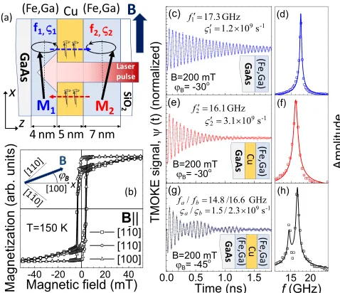
FIG. 1. (a) Scheme of the studied PSV structure and the ex-perimental idea. (b) SQUID magnetization curves measured for the three in-plane orientations ofB. The inset shows the used coordinate system. (c)–(f) TMOKE signals (left panels) and their FFT spectra (right panels) measured in (c), (d) a single galfenol layer of 4 nm on GaAs and (e), (f) a single 7-nm galfenol layer on Cu. At the chosen azimuthal angleϕB= −30◦, magnetization precession with large amplitude is excited in both single layers. (g), (h) TMOKE signal measured in PSV with no resonance of the precessing magnetizations. In (c)–(h), symbols show the experimental data; solid curves are fits with the parametersf andζshown in the respective panels.
M2can be aligned by an external magnetic field, based on their magnetic anisotropies. Figure1(b) shows the magnetization curves measured by superconducting quantum interference device (SQUID) magnetometry for three in-plane directions of the external fieldB, which are described by the azimuthal angleϕB(see inset). The easy axes of both layers are along the [100] crystal direction (ϕB =0◦). AtB >50 mT the structure is fully saturated alongBwithM1||M2.
Pump laser pulses (100-kHz repetition rate, 800-nm wave-length, 200-fs pulse duration, 10 mJ/cm2 fluence excitation density within a 100-µm focus spot) hit the PSV and launch magnetization precession by inducing ultrafast changes of the magnetic anisotropy [40]. The laser penetration depth of 25 nm exceeds the total thickness of the PSV layer sequence. Thus, the pump excites both FM layers, thereby triggering simultane-ously the precession ofM1andM2. The uncoupled precessions ofM1 andM2 are characterized by the frequenciesf1,2 and decay rates ζ1,2. Decay of magnetization precession occurs not only due to intrinsic processes, but also due to SP into the Cu layer [11,12]. The spin diffusion length in Cu exceeds significantly the spacer thickness [42], so that we expect the spin current, pumped by the precessing magnetization in one layer, to exert an ac torque on the magnetization of the other layer and thereby to affect its precession [23–26]. Coupled modes should form close to the resonancef1 =f2[27–29]. To observe the coupling, we monitored the magnetization through the transient polar magneto-optical Kerr effect (TMOKE) in a pump-probe experiment. The rotation of the polarization
plane ψ(t) of the linearly polarized probe beam focused to a spot of 60-µm diameter and reflected from the structure as a function of the time delay between the pump and probe pulses provides information about the temporal evolution of the total magnetizationM1+M2. Varying the external magnetic field, we tuned the magnetization precession parameters f1,2 and ζ1,2, as well as the contribution of SP to the magnetization dynamics.
For comparison, we performed corresponding measure-ments on single galfenol layers identical to those in the PSV. Figures 1(c) and 1(e) show the ψ(t) of these single lay-ers, revealing exponentially decaying oscillations. Their fast Fourier transforms (FFTs) in Figs.1(d)and1(f) show single spectral lines with the magnetization precession parameters listed in each panel (hereafter primes indicate the single-layer parameters). The much faster magnetization precession decay in the layer on top of Cu could be, for instance, due to SP into the Cu layer. The difference between f′
1 and f2′ is due to different magnetic anisotropies: a weak cubic one in (Fe,Ga)/Cu and a stronger cubic anisotropy with additional uniaxial and out-of-plane contributions in (Fe,Ga)/GaAs [38]. In the PSV both layers contribute to the measured magne-tization precession. The corresponding TMOKE in Fig.1(g)
contains two oscillating components with different frequen-cies, as seen from the FFT spectrum [Fig. 1(h)]. The signal can be well described as a sum of two damped sine functions with two parameter sets indexedaandb,
ψ(t)=Aasin(2πfat−φa) exp(−ζat)
+Absin(2πfbt−φb) exp(−ζbt). (1)
The fit toψ(t) in Fig.1(g)yieldsfa =14.8 GHz,ζa =1.5× 10⁹ s−1, f
b=16.6 GHz,ζb=2.3×10⁹ s−1. The solid line in Fig.1(h)shows the FFT spectrum corresponding to the fit. Because the frequency splitting of the spectral peaks is larger than their widths, we attribute the two components toM1and
M2, both precessing at their individual frequencies, so that we may assignfa,b=f1,2andζa,b =ζ1,2.
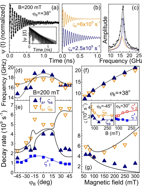
Owing to the different magnetic anisotropies of layers 1 and 2 we can change the detuning of the precession frequencies by varying the angle ϕB. Figure2(a) shows ψ(t) measured atB =200 mT applied atϕB= +38◦. Contrary to the case whereϕB = −45◦, here we can neither separate the signal into two independent oscillations with different frequencies, nor describe it as single-frequency oscillation with monoexponen-tial decay. The inset of Fig.2(a)showing the absoluteψ(t) on a logarithmic scale clearly indicates two decay rates ofψ(t). The analysis shows thatψ(t) is the sum of two components [see Fig. 2(b)] with close frequencies, fa ≈fb≈16 GHz, but significantly different decay rates,ζa ≈2.5×10⁹s−1and ζb≈6×10⁹s−1. The FFT spectrum in Fig.2(c)is fitted well by two spectral lines centered atf ≈16 GHz, one narrow and one broad. This result is our main experimental observation. Further analysis of the field dependences offa,bandζa,bproves that this effect is due to the collective precession ofM1and
M2, coupled by SP.
Figure2(d)showsfa,b(ϕB) atB=200 mT, from which we identify two dependences corresponding to the expected mag-netic anisotropies:fa(ϕB) complies with a cubic anisotropy plus an uniaxial distortion as observed in the single 4-nm
[image:3.590.40.279.62.268.2]14 16 18 20 (d) B=200 mT Fr eq ue nc y (GH z )
f
a,
af
b,
b-45 -30 -15 0 15 30 45 0 1 2 3 4 5 6 7 (e)
De
ca
y ra
te
(
1
0
9
s
-1)
B (deg)
'
1 10 15 20 (f) B=+38 o50 100 150 200 250 300 2 4 6 8 10 12 14 (g)
Magnetic field (mT)
100 250 2 4 b B=-45 o a (1 0
9 s -1 ) B (mT) 100 250 '1 '2 B=30 o
0.0 0.5 1.0
(a) B=200 mT ( t) (n o rm a liz e d ) B=+38 o
0.0 0.5 1.0
(b) a=2.5x10 9 s-1 b=6x10 9 s-1
Time (ns) 10 15 20 25
Am p lit ud e Frequency (GHz) (c) 0 1 Time (ns) | |(t )
FIG. 2. (a) Experimental signal (symbols) measured in the PSV at resonant conditions and fit by Eq. (1) (solid line). The inset shows
|ψ(t)|in logarithmic scale. (b) Long- and short-living precessional modes contributing toψ(t) with respective decay rates, obtained by fitting by Eq. (1). (c) FFT spectra of the experimental signal (symbols), the fit (black solid line), and the long- and short-living modes (dark blue and orange lines, respectively). (d), (e) Azimuthal dependences of the precession frequencies fa,b(ϕB) [(d)] and the decay ratesζa,b(ϕB) [(e)] atB=200 mT. (f), (g) Field dependences
fa,b(B) [(f)] andζa,b(B) [(g)] atϕB= +38◦. The insets in (g) show the field dependences of the decay ratesζa,b(B) measured in the PSV atϕB= −45◦ (left inset) andζ1′,2(B) in the single-layer structures
atϕB= +30◦(right inset). In (d)–(g) the values obtained from the experiment are shown by symbols, the sizes of which correspond to the fit error; the lines show the calculated dependences. In the insets the lines are guides for the eye.
Fe0.81Ga0.19layer on GaAs;fb(ϕB) agrees with the weak cubic anisotropy of the 7-nm Fe0.81Ga0.19layer on Cu. At any tested direction ofB, the best fit of the data gives two frequencies contributing to the TMOKE signal, though at some angles (e.g.,
ϕB >30◦) they have very close values.
Contrary to the precession frequencies, the decay rates in Fig.2(e)do not demonstrate a behavior corresponding to precessions in single layers. ForϕB ≈ −15◦and+30◦ < ϕB <
+45◦, where the precession frequencies almost coincide, we
observe a pronounced splitting of the decay rates as shown above for ϕB= +38◦. We obtain ζa≈2.5×10⁹s−1 and ζb≈5.5×10⁹s−1atϕB ≈ −15◦, andζa ≈2×10⁹s−1 and ζb≈7×10⁹s−1 for +30◦< ϕB <+45◦. For comparison, ζ′
1(ϕB) measured on the Fe0.81Ga0.19/GaAs structure [see the blue symbols in Fig.2(e)] shows a smooth variation around
-45 -30 -15 0 15 30 45
0 5 10 15 20
damping
c
oefficients
x10
3 β1 β2 α1 α2ϕ
B(degree)
(b)
B=200 mT
100 150 200 250 300
0 10 20 30 α1 α2 β1 β2
Magnetic field (mT)
(c)
ϕB=+38 o
Long-living mode
Short-living mode
(a)
M
1α
1+
β
1−β
2M
2β
2β
1α
2+
β
2−β
1M
1 β2M
2β1
α2+β2+β1
α1+β1+β2
FIG. 3. (a) Qualitative and simplified description of the two collective precessional modes mediated by the SP. The upper sketch demonstrates the long-living mode, in which the reciprocal spin currents generate spin torques supporting the precession. The lower panel shows the short-living mode, in which the contribution of the spin currents is destructive for the precession. (b), (c) Dependences of the damping coefficientsα1,2andβ1,2on (b)ϕBand (c)Bobtained
from modeling of the experimental dependences.
a broad maximum at ϕB =0◦, without the abrupt changes observed for the PSV.
We examine also the field dependences of the precession parameters at a fixed direction of B, where the resonance condition is fulfilled. Figures2(f)and2(g)showfa,b(B) and ζa,b(B) at ϕB = +38◦. Across the scanned range of B the two components contributing to ψ(t) have closely matched frequencies, within the experimental error. Their decay rates, in contrast, show a pronounced increasing splitting at B >
100 mT. This behavior is different from the dependences of
ζa,b(B) atϕB = −45◦ where no resonance is present and we find a small, field-independent difference between the two decay rates [see the left inset of Fig.2(g)]. The dependence
ζa(B) atϕB = +38◦agrees with the dependences ofζ1′(B) in the single layer shown in the right inset of Fig.2(g)(though measured at a slightly smaller ϕB when both layers exhibit large precession amplitudes). However, ζb increases with B much faster thanζ′
2. This is an indication of the SP contribution to the decay of this mode.
[image:4.590.45.282.58.368.2] [image:4.590.302.551.62.308.2]A. P. DANILOVet al. PHYSICAL REVIEW B98, 060406(R) (2018)
versa. The temporal evolutions of M1 and M2 coupled by this dissipative mechanism can be described by the modified Landau-Lifshitz-Gilbert equations [27],
dMi
dt =γgB (i)
eff×Mi+ αi+βi
M Mi× dMi
dt
−βMjMj×
dMj
dt , (2)
where γg is the gyromagnetic ratio, B (i)
eff is the effective magnetic field determined by the magnetic anisotropy and the applied magnetic field, andiandjdenote the magnetic layers (i=j). The solution of the linearized version of Eq. (2) yields coupled precessional modes. If the precession frequencies of the individual layers are well separated and the coupling is weak,ζ1,2 ≈α1,2+β1,2. The situation drastically changes close to resonance, when the frequency splitting obeys the following condition:
f <
√
β1β2
2π γg(2B+µ0M), (3)
whereµ0is the vacuum permeability andMis the saturation magnetization of the FM layers. In this case the magnetiza-tions precess with the same frequencies, but show a double-exponential decay, representing a superposition of two modes with decay rates,
ζa,b ∼
α1+β1+α2+β2∓
4β1β2+(α1+β1−α2−β2)2
2 .
The difference between the damping parameters for the two coupled modes due to SP is illustrated in Fig.3(a). The long-living mode with suppressed damping can be considered as the two magnetizations precessing in phase. Then the spin torques from the two magnetizations support the joint precession. The damping of this mode,ζa, is close to the intrinsic one. The short-living mode, in contrast, represents the counterphase precession ofM1 andM2, which causes a mutual damping. Approximately,ζa−ζb ∼2√β1β2.
To substantiate our interpretation, we modeled the magne-tization kinetics in the PSV numerically. The solid curves in Figs. 2(d)–2(g) give the calculated results using the follow-ing magnetic anisotropy parameters: K1(1)=20 mT, K⊥(1)=
−40 mT,K||(1)=20 mT for the bottom 4-nm galfenol layer, and
K1(2)=8 mT,K⊥(2)= −65 mT,K||(2)=0 mT for the top one. The parametersK1,⊥,||represent the cubic, perpendicular, and
in-plane uniaxial anisotropies, respectively. The magnetization was taken to beµ0M=1.59 T [39]. The angular and field dependences of the coefficientsα1,2 andβ1,2 providing the best agreement with the experimental data are summarized in Figs.3(b)and3(c). The dependences ofα1,2correspond well to the ζ′
1,2(ϕB, B) for the single layers, though in the PSV the absolute values are a bit larger. The dependence ofβ1,2 in Fig.3(b)demonstrates a pronounced angular anisotropy of the SP efficiency. Indeed, in the PSV the decay atϕB = −45◦ for both layers is about the same as that of the long-living mode atϕB >25◦, which is close to the intrinsic one. Since in the single 4-nm galfenol layer the decay rates forϕB = ±45◦ are similar, the SP contribution to the decay forϕB = −45◦is marginal. Note that a strong SP anisotropy in a PSV with an in-plane magnetic anisotropy of one layer had been reported in Ref. [25]. The SP coefficients also depend on the magnetic
field as seen in Fig.3(c). Indeed, for the selectedϕB = +38◦, the precession frequencies are close to resonance across the whole range of magnetic fields, and we always observe coupled modes. Thus, the observed increase of the decay rate splitting withBsuggests a corresponding dependence ofβ1,2(B) [29]. This agrees with the dependence of ζ′
2(B) measured in the Fe0.81Ga0.19/Cu/GaAs structure and shown in the right inset of Fig.2(g). Whenβ1,2become large enough to fulfill Eq. (3) (at B >100 mT), the strongly coupled regime with a pronounced splitting of decay rates is formed.
It is interesting to note that the demonstrated collective precession of two magnetizations mediated by SP is a rare example of pure dissipative coupling, which in a quantum-mechanical approach would be described by a non-Hermitian matrix [44]. This coupling regime for two oscillators results in the formation of two degenerate modes with split decay rates. Although the realization of dissipative coupling promises inter-esting effects, in particular in nano-optomechanical structures [45], the number of systems with such a coupling is limited so far [46,47]. To the best of our knowledge, precessing magneti-zations dynamically coupled by SP have not been considered in this context. Indeed, in FMR experiments on similar structures, the magnetizations are driven by microwaves, which precisely set the precession phase for both magnetizations. This results in the observation of only one collective mode: either the long-living mode for parallel magnetizations [27–29] or the short-living mode if the magnetizations are antiparallel [28]. The pulsed optical excitation in our experiment triggers in-stantly the precession of the two magnetizations, and the initial precession phases are determined by the anisotropy parameters of the layers. This allows us to observe both modes in the collective magnetization dynamics. Our observations are made possible by the use of ferromagnetic materials in a spin valve which possess a specific combination of magnetic properties: magnetic anisotropy with high sensitivity to ultrafast optical excitation, in combination with weak intrinsic damping and a high spin pumping rate. This combination is realized in galfenol used in the studied PSV.
To conclude, we demonstrated that ultrafast optical ex-citation of the magnetization precession is a powerful tool for triggering pure spin currents in ferromagnetic multilayer structures without the need for applying microwaves. For our pseudospin valve this was confirmed by the observation of collective precessional modes dissipatively coupled by the spin pumping. The optical excitation allows one to launch a superposition of these modes over a wide frequency range not achievable for microwave driving. The use of galfenol-based spin valves allows also designing of a complex spin current temporal pattern by resonant phonon driving of the magnetization precession in a spin valve structure inserted into a phononic nanoresonator [48].
We are grateful to Andrey Akimov, Davide Bossini, and An-drew Armour for fruitful discussions. This work was supported by the Deutsche Forschungsgemeinschaft in the frame of the International Collaborative Research Center TRR160 (Project B6), and by the Engineering and Physical Science Research Council (Grant No. EP/H003487/1) through support for the growth and characterization of the galfenol-based nanostruc-tures in the University of Nottingham. The experimental
studies in the Ioffe Institute were performed under support of the Russian Science Foundation (Grant No. 16-12-10485).
The Volkswagen Foundation supported the cooperative work with Lashkarev Institute (Grant No. 90418).
[1] Y. Tserkovnyak, A. Brataas, and G. E. W. Bauer,Phys. Rev. Lett.
88,117601(2002).
[2] M. V. Costache, M. Sladkov, S. M. Watts, C. H. van der Wal, and B. J. van Wees,Phys. Rev. Lett.97,216603(2006). [3] Y. Kajiwara, K. Harii, S. Takahashi, J. Ohe, K. Uchida, M.
Mizuguchi, H. Umezawa, H. Kawai, K. Ando, K. Takanashi, S. Maekawa, and E. Saitoh,Nature (London)464,262(2010). [4] C. W. Sandweg, Y. Kajiwara, A. V. Chumak, A. A. Serga, V. I.
Vasyuchka, M. B. Jungfleisch, E. Saitoh, and B. Hillebrands, Phys. Rev. Lett.106,216601(2011).
[5] K. Ando, S. Takahashi, J. Ieda, H. Kurebayashi, T. Trypiniotis, C. H. W. Barnes, S. Maekawa, and E. Saitoh,Nat. Mater.10, 655(2011).
[6] M. Jamali, J. S. Lee, J. S. Jeong, F. Mahfouzi, Y. Lv, Z. Zhao, B. K. Nikoli, K. A. Mkhoyan, N. Samarth, and J.-P. Wang,Nano Lett.15,7126(2015).
[7] Z. Qiu, J. Li, D. Hou, E. Arenholz, A. T. N’Diaye, A. Tan, K.-I. Uchida, K. Sato, S. Okamoto, Y. Tserkovnyak, Z. Q. Qiu, and E. Saitoh,Nat. Commun.7,12670(2016).
[8] Z. Tang, E. Shikoh, H. Ago, K. Kawahara, Y. Ando, T. Shinjo, and M. Shiraishi,Phys. Rev. B87,140401(2013).
[9] M. Althammer, M. Weiler, H. Huebl, and S. T. B. Goennenwein. inSpintronics for Next Generation Innovative Devices, edited by K. Sato and E. Saitoh (Wiley, Hoboken, NJ, 2016), p. 111. [10] A. Brataas, Y. Tserkovnyak, G. E. W. Bauer, and B. I. Halperin,
Phys. Rev. B66,060404(R)(2002).
[11] Y. Tserkovnyak, A. Brataas, and G. E. W. Bauer,Phys. Rev. B
66,224403(2002).
[12] Y. Tserkovnyak, A. Brataas, G. E. W. Bauer, and B. I. Halperin, Rev. Mod. Phys.77,1375(2005).
[13] R. Urban, G. Woltersdorf, and B. Heinrich,Phys. Rev. Lett.87, 217204(2001).
[14] S. Mizukami, Y. Ando, and T. Miyazaki,Phys. Rev. B66,104413 (2002).
[15] E. Saitoh, M. Ueda, H. Miyajima, and G. Tatara,Appl. Phys. Lett.88,182509(2006).
[16] K. Ando, Y. Kajiwara, S. Takahashi, S. Maekawa, K. Takemoto, M. Takatsu, and E. Saitoh,Phys. Rev. B78,014413(2008). [17] O. Mosendz, J. E. Pearson, F. Y. Fradin, G. E. W. Bauer, S. D.
Bader, and A. Hoffmann,Phys. Rev. Lett.104,046601(2010). [18] L. Feiler, K. Sentker, M. Brinker, N. Kuhlmann, F.-U. Stein, and
G. Meier,Phys. Rev. B93,064408(2016).
[19] H. J. Jiao and G. E. W. Bauer,Phys. Rev. Lett.110, 217602 (2013).
[20] C. Hahn, G. de Loubens, M. Viret, O. Klein, V. V. Naletov, and J. Ben Youssef,Phys. Rev. Lett.112,179901(E)(2014). [21] D. Wei, M. Obstbaum, M. Ribow, C. Back, and G. Woltersdorf,
Nat. Commun.5,3768(2014).
[22] M. Weiler, J. M. Shaw, H. T. Nembach, and T. J. Silva,Phys. Rev. Lett.113,157204(2014).
[23] M. K. Marcham, L. R. Shelford, S. A. Cavill, P. S. Keatley, W. Yu, P. Shafer, A. Neudert, J. R. Childress, J. A. Katine, E. Arenholz, N. D. Telling, G. van der Laan, and R. J. Hicken,Phys. Rev. B87,180403(R)(2013).
[24] J. Li, L. R. Shelford, P. Shafer, A. Tan, J. X. Deng, P. S. Keatley, C. Hwang, E. Arenholz, G. van der Laan, R. J. Hicken, and Z. Q. Qiu,Phys. Rev. Lett.117,076602(2016).
[25] A. A. Baker, A. I. Figueroa, C. J. Love, S. A. Cavill, T. Hesjedal, and G. van der Laan,Phys. Rev. Lett.116,047201(2016). [26] B. Kardasza, O. Mosendz, and B. Heinrich,J. Appl. Phys.103,
07C509(2008).
[27] B. Heinrich, Y. Tserkovnyak, G. Woltersdorf, A. Brataas, R. Urban, and G. E. W. Bauer,Phys. Rev. Lett.90,187601(2003). [28] X. Joyeux, T. Devolder, J.-V. Kim, Y. Gomez de la Torre, S.
Eimer, and C. Chappert,J. Appl. Phys.110,063915(2011). [29] H. Yang, Y. Li, and W. E. Bailey,Appl. Phys. Lett.108,242404
(2016).
[30] A. Kirilyuk, A. V. Kimel, and T. Rasing,Rev. Mod. Phys.82, 2731(2010).
[31] M. van Kampen, C. Jozsa, J. T. Kohlhepp, P. LeClair, L. Lagae, W. J. M. de Jonge, and B. Koopmans,Phys. Rev. Lett.88,227201 (2002).
[32] A. Melnikov, I. Razdolski, T. O. Wehling, E. T. Papaioannou, V. Roddatis, P. Fumagalli, O. Aktsipetrov, A. I. Lichtenstein, and U. Bovensiepen,Phys. Rev. Lett.107,076601(2011). [33] D. Rudolf, C. La-O-Vorakiat, M. Battiato, R. Adam, J. M.
Shaw, E. Turgut, P. Maldonado, S. Mathias, P. Grychtol, H. T. Nembach, T. J. Silva, M. Aeschlimann, H. C. Kapteyn, M. M. Murnane, C. M. Schneider, and P. M. Oppeneer,Nat. Commun.
3,1037(2012).
[34] T. Kampfrath, M. Battiato, P. Maldonado, G. Eilers, J. Nötzold, S. Mährlein1, V. Zbarsky, F. Freimuth, Y. Mokrousov, S. Blügel, M. Wolf, I. Radu, P. M. Oppeneer, and M. Münzenberg,Nat. Nanotechnol.8,256(2013).
[35] G.-M. Choi, B.-C. Min, K.-J. Lee, and D. Cahill,Nat. Commun.
5,4334(2014).
[36] A. J. Schellekens, K. C. Kuiper, R. R. J. C. de Wit, and B. Koopmans,Nat. Commun.5,4333(2014).
[37] A. Alekhin, I. Razdolski, N. Ilin, J. P. Meyburg, D. Diesing, V. Roddatis, I. Rungger, M. Stamenova, S. Sanvito, U. Boven-siepen, and A. Melnikov,Phys. Rev. Lett.119,017202(2017). [38] D. E. Parkes L. R. Shelford, P. Wadley, V. Holy, M. Wang, A. T.
Hindmarch, G. van der Laan, R. P. Campion, K. W. Edmonds, S. A. Cavill, and A. W. Rushforth,Sci. Rep.3,2220(2013). [39] J. B. Restorff, M. Wun-Fogle, K. B. Hathaway, A. E. Clark, T. A.
Lograsso, and G. Petculescu,J. Appl. Phys.111,023905(2012). [40] V. N. Kats, T. L. Linnik, A. S. Salasyuk, A. W. Rushforth, M. Wang, P. Wadley, A. V. Akimov, S. A. Cavill, V. Holy, A. M. Kalashnikova, and A. V. Scherbakov,Phys. Rev. B93,214422 (2016).
[41] Z. Celinski and B. Heinrich,J. Magn. Magn. Mater.99,L25 (1991).
[42] S. Yakata, Y. Amdo, T. Miazaki, and S. Mizukami,Jpn. J. Appl. Phys45,3892(2006).
dipole-A. P. DANILOVet al. PHYSICAL REVIEW B98, 060406(R) (2018)
dipole interaction between two ultrathin films, which in the used experimental geometry may be considered as two infinite planes, is zero. Dynamical strain generated by the magnetization precessing with an amplitude of∼10−2Mis two small (
∼10−6)
[39] to affect the magnetization of another layer.
[44] D. Dragoman and M. Dragoman,Quantum-Classical Analogies
(Springer, Berlin, 2013), p. 119.
[45] W. P. Bowen and G. J. Milburn,Quantum Optomechanics(CRC Press, Boca Raton, FL, 2015).
[46] M. Li, W. H. P. Pernice, and H. X. Tang,Phys. Rev. Lett.103, 223901(2009).
[47] M. Wu, A. C. Hryciw, C. Healey, D. P. Lake, H. Jayakumar, M. R. Freeman, J. P. Davis, and P. E. Barclay,Phys. Rev. X4, 021052(2014).
[48] J. V. Jäger, A. V. Scherbakov, B. A. Glavin, A. S. Salasyuk, R. P. Campion, A. W. Rushforth, D. R. Yakovlev, A. V. Akimov, and M. Bayer, Phys. Rev. B 92, 020404(R) (2015).