Int. J. Electrochem. Sci., 10 (2015) 7521 - 7534
International Journal of
ELECTROCHEMICAL
SCIENCE
www.electrochemsci.org
Optimization of Distributed Cylindrical Interconnect Ribs for
Anode- and Cathode-Supported Solid Oxide Fuel Cell
Xiang Gao, Qiang Zhang, Wenxuan Zhang, Daifen Chen*
School of Energy and Power Engineering, Jiangsu University of Science and Technology, Zhenjiang 212003, China
*
E-Mail: [email protected]
Received: 11 May 2015 / Accepted: 25 June 2015 / Published: 28 July 2015
This paper presents a 3D multi-physics mathematic model to study the influence of distributed cylindrical interconnect ribs on solid oxide fuel cell (SOFC) performance; and achieve the optimizing conclusions. The numerical simulation reveals that the interconnect structure, rib size, pitch width and contact resistance have significant effect on the the cell output; and there exists an optimum rib size to maximize the output current density. In addition, as there are significant differences working details between anode and cathode zone, as well as between anode-supported and cathode-supported, they should be optimized separately. Finally, the relationships between the optimized results and contact resistances for different SOFC types are concluded into simple expressions respectively to provide generality in practical application.
Keywords: SOFC; distributed cylindrical interconnect; 3D multi-physics model; design optimization
1. INTRODUCTION
With the continuing increase in fuel price and the global scope of the pollutant emission standards, there is an urgent hope to obtain a kind of alternative energy sources with high efficient and low pollution [1]. SOFC as a kind of novel energy conversion device has attracted extensive attention of domestic and foreign researchers. Compared with other kinds of fuel cells, SOFC which has the advantages of high reliability, long life, low emission and high efficiency of energy conversion is an efficient and environmentally friendly green power plant [2-4]. Therefore, it is regarded as one of the most promising new energy technology in the 21st century [5, 6].
density of SOFC is, the more serious polarization losses are. In general, the polarization losses of SOFC mainly consist of three forms [7,8]: (1) the ohmic polarization is caused by the ionic and electronic conduction, which is associated with the current flow path and the conductivity of electrodes and electrolyte, (2) the activation polarization is caused by the electrochemical reaction, which relies on the reaction temperature and properties of electrode materials, (3) the concentration polarization is caused by the mass transfer resistance, which is related to the reactants delivery and products removal to and from the electrochemical reaction site.
Among the factors which affect the performance of SOFC, one of the main reasons resulting in the poor cell stack performance is the extra damage caused by the geometric structure of the interconnector. Connecting structure of cell stack is called as the interconnector which is a significant element of SOFC stack and plays a role of mechanical support and electrical connections between the anode and cathode plates. Small grooves in interconnector are known as channels which carry on the tasks of distributing the fuel and air gas. The ribs, which are applied to separate and define the channels and collect the current, are directly linked to electrodes. Normally, two aspects should be considered for the design of the interconnector [9]: (i) the selection of the geometry of the interconnector, (ii) the optimization for the size and spacing of the selected interconnector. Taking into account the problems of the manufacturing cost, stress, technology conditions as well as other factors, the sizes of rib cannot be too small. What’s more, the existing contact resistance between the ribs and electrodes will further increase in fuel cell operation due to oxidation of interconnect materials [10]. From the design point of view, the bigger fraction of the cell area is covered by the wider rib and contributes to reduce the contact resistance between the electrode and rib. Therefore, the rib could transmit the electrical current very well, cut down on ohmic losses and shorten the pathway of current from the three-phase boundary to interconnector. But with the increase of the width of the rib, the channel will be narrowed and fuel or air does not diffuse well underneath the wider rib. Hence, more homogeneous distribution of reactive gases across the area of the electrolyte surface will be done by narrow rib and thus electrochemical reaction will be improved. Due to the existence of the above two kinds of competition, there must be a compromise between the rib and channel sizes which is able to achieve a balance between a sufficiently large electrochemical reaction area and a shorter current collection pathway.
In most of the currently investigated planar type solid oxide fuel cells, conventional straight interconnectors are widely used to distribute gas species and collect the current. However, the multiple straight gas channels in such a design are separated from each other [11]. From the standpoint of mass transfer, the flows of gas species are divided, and thus the communication among flows between different channels is impossible. What is more, there is a larger contact area between the electrode and interconnector in this type of design of flow field and thus concentration loss is also relatively larger. In order to overcome this defect, novel interconnector designs have commanded increasing attention and recognition by researchers.
numerical analysis. A novel symmetrical planar SOFC design with micro-flow channels has been proposed by Shi et al [15]. Their studies showed that this type of design may not only enhance the amount of fuel and air feed but also make the cell design more intensively. Li et al. [11] put forward a new type SOFC with distributed cylindrical current collectors to obtain higher power densities by maximizing the active area for the reactants as well as enhancing the mass transfer in SOFC.
However, it should be pointed out that the existing numeric modeling about the novel interconnector of the optimized design have been put into effect with two underlying hypotheses: (i) equal contact resistance for the anode-rib and cathode-rib interfaces and (ii) equal size of the optimum anode rib and cathode rib. But, based on our previous research on conventional straight interconnectors [16], we have already known that contact resistance for the anode-rib and cathode-rib interfaces are obviously different. There are also differences in regard to the optimal size of rib for anode and cathode. Moreover, the existing theoretic analysis and experimental tests demonstrate that the anode rib and the cathode rib should use different sizes during the optimization process of the SOFC stack. These conclusions are also applicable to the novel interconnector. So it is very necessary to further optimize the interconnector structure in order to more accurately reflect SOFC performance.
In a variety of interconnector designs, distributed cylindrical current collector has been recognized by the researchers due to its significant margin. Therefore, there is a strong need to further improve the performance of SOFC with distributed cylindrical interconnector without the above two assumptions. In this paper, a three-dimensional multi-physics model for SOFCs with composite electrodes is proposed and theoretical analysis is conducted. The influences of the anode and cathode ribs are examined independently for different electrode-rib contact resistances, pitch width and electrodes support structure. Finally, the optimum anode and cathode rib sizes for different contact resistances are acquired.
2. NUMERICAL SIMULATIONS
2.1 Geometrical Model
Figure 1. SOFC stack with distributed cylindrical current collector
Figure 2. A repeating unit of cell stack
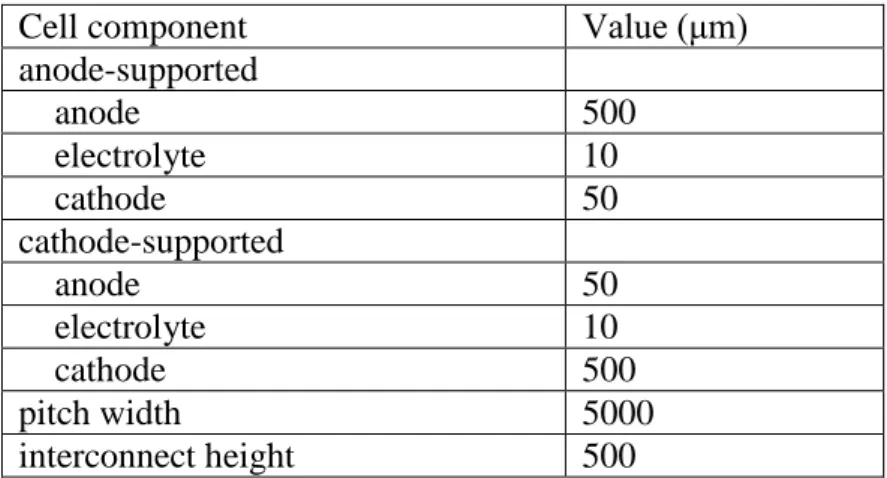
Table 1. Geometric parameters
Cell component Value (μm)
anode-supported
anode 500
electrolyte 10
cathode 50
cathode-supported
anode 50
electrolyte 10
cathode 500
pitch width 5000
interconnect height 500
2.2 Gas transport Equations
For a binary component system (fuel with H2 and H2O, or air with O2 and N2), the total molar
eff 12 eff
12 1 2 2 1
1 2 eff
12 1 2 2 1 '
eff iK
i eff eff i
K K
eff eff K K
i eff eff
tot K K
diffusion convection
i i i i i
D D
N c
D x D x D
D D k
c p
RTc D x D x D
k p
D c c N N
(1)
where Niis the molar flux of species i; eff ij
D is the effective binary diffusion coefficient; Dikeff is the effective Knudsen diffusion coefficient of species i; ci is the molar concentration of species i; xi is the molar fraction of species i; ctot is the total molar concentration of the binary mixture; R is the universal gas constant; T is the absolute temperature; p is the total gas pressure; k is the permeability coefficient and μ is the viscosity coefficient. Di is the equivalent diffusion coefficient of species i and k’ is the equivalent permeability coefficient of the binary system.
eff ij
D and Dikeffcan be expressed as follows [18]:
0.5 8 1.75
2 1/3 1/3
3.198 10 1 1 eff ij i j i j T D M M
p v v
(2)
2 8 3 eff ik g i RT D r M
(3)
where is the porosity; is the tortuosity factor; vi and vj are the diffusion volume of species i and j, respectively; Mi and Mj are the molar mass of species i and j, respectively; rgis the pore radius.
2.3 Conductive equations
Electron current density and ion current density are determined by the charge conservation equation, which can be represented as [10]:
eff
el el el current
i S
(4)
eff
io io io current
i S
(5)
where iel and iio are the electronic current density vector and ion current density vector, respectively; eff
el
and eff io
are the effective electronic conductivity and the effective ionic conductivity, respectively;el and ioare the electronic potential and ionic potential, respectively; Scurrent is the current source. Due to the charge conservation, the source of electronic current is also the sink of ionic current.
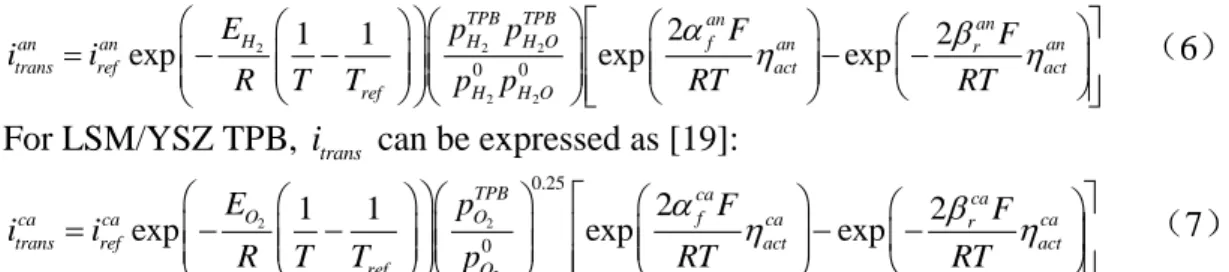
2.4 Butler-Volmer equations
2 2 2
2 2
0 0
2 2
1 1
exp exp exp
TPB TPB an an
H H H O f
an an an r an
trans ref act act
ref H H O
E p p F F
i i
R T T p p RT RT
(6) For LSM/YSZ TPB, itrans can be expressed as [19]:
2 2
2
0.25
0
2
1 1 2
exp exp exp
TPB ca ca
O O f
ca ca ca r ca
trans ref act act
ref O
E p F F
i i
R T T p RT RT
(7) where f and r are the forward and reverse reaction symmetric factor, respectively;
2 H E and 2 O E are the activation energies for the anode and cathode electrochemical reactions, respectively; irefan and irefca are often deduced from experiments or assigned empirically at the reference temperature of Tref ;
2 0 H p and 2 0 H O
p are the partial pressure of H2 and H2O at the fuel channel/anode interface, respectively; pO02is the partial pressure of O2 at the air channel/cathode interface; pTPBH2 and 2
TPB H O
p are the partial pressure of H2 and H2O at the anode TPB, respectively; pOTPB2 is the partial pressure of O2 at the cathode TPB; F is Faraday constant; an
act
and ca act
are anode and cathode activation polarization, respectively. The values of input parameters used in the model are shown in Table 2.
Table 2. Model parameters
Parameter Value
Temperature, T(℃) 800
Operation voltage, Vop (V) 0.7
Tortuosity factor,
3.5Porosity,
0.3Mole fraction of fuel and air
2
H x ,
2
H O
x 0.7, 0.3
2
O x ,
2
N
x 0.21, 0.79
Inlet concentration (mol m-3)
2 0 H c , 2 0 H O
c 7.95, 3.41
2 0 O c , 2 0 N
c 2.38, 8.97
Activation energies for the anode,
2
H
-1 (J mol )
E 1.2×10⁵
Activation energies for the cathode,
2
O
-1 (J mol )
E 1.3×10⁵
Exchange transfer current density of anode, irefan
A m-1
2000Exchange transfer current density of cathode, irefca
A m-1
860Reaction symmetric factor for anode, anf , an r
2, 1
Reaction symmetric factor for cathode, caf , ca r
2.5 Boundary conditions
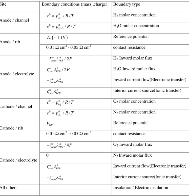
In order to solve the above-mentioned partial-differential equations, it is necessary to set up the reasonable boundary conditions, including gas transport equations, ionic conductive equation and electronic conductive equation, as described in Table 3.
Table 3. Boundary settings in numerical simulation.
Site Boundary conditions (mass ,charge) Boundary type
Anode / channel 2
0 0 / / H
c p R T H2 molar concentration
2
0 0 / / H O
c p R T H2O molar concentration
Anode / rib E0
1.1V
Reference potential 0.01 Ω cm2 - 0.05 Ω cm2 contact resistance
Anode / electrolyte
/ 2 an A trans TPB
i F
H2 Inward molar flux
/ 2 an A trans TPB
i F H2O Inward molar flux
an A trans TPB i
Inward current flow(Electronic transfer)
an A trans TPB
i Interior current source(Ionic transfer)
Cathode / channel 2
0 0 / / O
c p R T O2 molar concentration
2
0 0 / / N
c p R T N2 molar concentration
Cathode / rib
OP
V Reference potential
0.01 Ω cm2
- 0.05 Ω cm2 contact resistance
Cathode / electrolyte
/ 4 ca A trans TPB
i F
O2 Inward molar flux
0 N2 Inward molar flux
ca A trans TPB
i Inward current flow(Electronic transfer)
ca A trans TPB i
Interior current source(Ionic transfer)
All others - Insulation / Electric insulation
Note: A TPB
3. RESULTS AND DISCUSSION
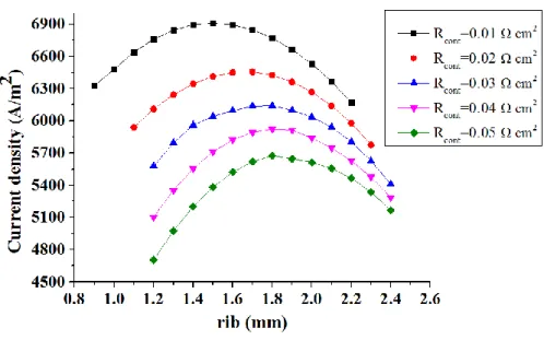
The interconnector is one of the principal components of the planar SOFC and the size of the rib has a great effect on the cell stack performance. To further investigate the influence of the rib size on the cathode-supported SOFC performance, the current density output for a defined pitch width of 5 mm is examined by changing the rib size. The results of the calculation are shown in Fig. 3. It is interesting to see that every curve has similar variation tendency. For a fixed contact resistance, there exists an optimum rib size to get the best output current density. The maximum current densities for contact resistance of 0.01, 0.02, 0.03, 0.04, 0.05 Ω cm2
are 6909, 6457, 6138, 5922 and 5611 A m−2, respectively and the corresponding optimal rib sizes are 1.55, 1.67, 1.76, 182 and 1.86 mm. As might be expected, with the increment of the contact resistance, the maximum cell output will be reduced, while the optimum rib size increases with the increment of the contact resistance.
When the contact resistances were 0.01, 0.02, 0.03, 0.04 and 0.05 Ω cm2
respectively, optimum ribs size corresponding current densities increase by 2.22%, 5.69%, 10.02 %, 16.05%, 20.35% compared with a defined rib size of 1.2 mm. This result indicates that with the increment of the contact resistance, rib size effect on the output current is more and more significant. Thus, the influence of rib size on the performance of SOFC cannot be neglected.
Another important phenomenon from Fig. 3 is that the optimized output of 5922 A m−2 for the contact resistance of 0.04 Ω cm2
is 6.15% higher than that of 5579 A m−2 for the contact resistance of 0.03 Ω cm2
with a rib size of 1.2 mm. This is a result of great significance, which indicates that the performance of the cell with smaller contact resistance is not necessarily superior to one with larger contact resistance if the rib size isn’t selected properly. Therefore, choosing the rib size appropriately is favorable to improve the cell performance. Seeking optimum rib size has become a critical problem for the design of the interconnector for SOFC.
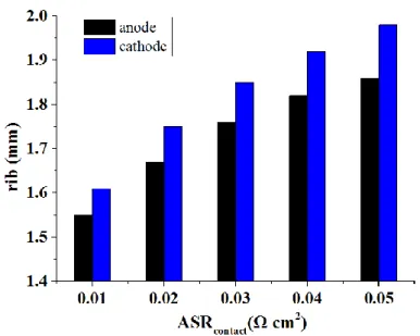
Fig. 4 shows the optimal rib size as functions of the contact resistance for pitch=5 mm. It is very interesting to see that in terms of the optimal rib size, there are significant differences in between the anode and cathode. Moreover, such disparity becomes bigger and bigger with the increase of contact resistance. With the contact resistance varying from 0.01 Ω cm2 to 0.05 Ω cm2, compared with the optimal anode rib sizes, the optimal rib sizes of cathode increase by 3.87%, 4.79%, 5.11%, 5.49% and 6.45%, respectively. This is because the thickness of the cathode is about ten times of that for the anode thickness for a cathode-supported SOFC and thus the wider rib limits the diffusion of gas in the thin anode, while the variable does not significantly influence on gas diffusion at the cathode side. Therefore, the optimum anode rib is not applicable to the cathode side and they should be optimized separately.
Figure 4. The difference of the optimum rib size between the anode and cathode.
Kong and Liu previous studies on the traditional interconnector have shown that the optimum rib size relate only to the electrode-rib contact resistance and pitch width [16, 20]. As a result, the relationship between the optimum rib size and electrode-rib contact resistance and pitch width will be discussed in the next articles.
Based on 3D finite element model, a range of optimization calculations are carried out in order to obtain the optimum rib sizes for fixed pitch widths. The calculation results are shown in Fig. 5 and 6. The discrete points and lines on the chart represent optimal values and fitted values, respectively. Obviously, the optimal values agree well with the fitted values. As a result, we can believe the optimal rib size is approximately linear with the contact resistance for a given pitch width and can be expressed as:
rib contact
d A B R (8)
max
= rib 100% rib
i i
i
(9)
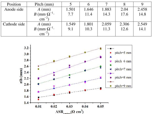
where imaxis the output current density corresponding to the optimum rib size, while irib is the current density for the rib size determined by Equation 8. The calculations demonstrate that Equation 8 shows a high accuracy: the maximum difference between imax and irib is less than 0.5%. Moreover, comparing with the parameter λ of the anode side, the cathode side fitted values approach better optimal values, and the error margin is smaller. Therefore, it can be taken as a formula for solving the optimal rib. Finally, to facilitate its application in engineering, Table 4 lists the values of A and B for a serious of pitch width of the cathode-supported SOFC.
Table 4. The values of A and B for the cathode-supported SOFC.
Position Pitch (mm) 5 6 7 8 9
Anode side A (mm) B (mm·Ω−1·
cm−2)
1.501 7.7
1.646 11.4
1.883 14.3
2.04 17.6
2.458 14.8 Cathode side A (mm)
B (mm·Ω−1· cm−2)
1.549 9.1
1.801 10.3
2.059 11.3
2.306 12.6
2.549 14.1
Figure 5. Dependence of the optimum anode rib size on the contact resistance and pitch width.
result, a further optimization should be made for the anode-supported SOFC with distributed cylindrical interconnector. The optimization results are shown in Fig. 9 and 10.
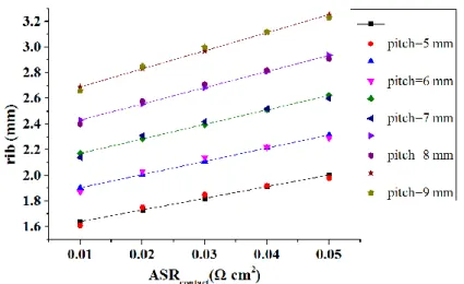
Figure 6. Dependence of the optimum cathode rib size on the contact resistance and pitch width.
Figure 7. The difference of the optimum anode rib size of anode- and cathode-supported SOFC.
Table 5. The values of A and B for the anode-supported SOFC.
Position Pitch (mm) 5 6 7 8 9
Anode side A (mm) B (mm·Ω−1·
cm−2)
1.778 12.4
1.962 15.8
2.055 20.9
2.241 22.1
2.642 22.8 Cathode side A (mm)
B (mm·Ω−1· cm−2)
1.575 6.1
1.957 5.9
2.362 5.4
2.751 5.7
3.197 5.1
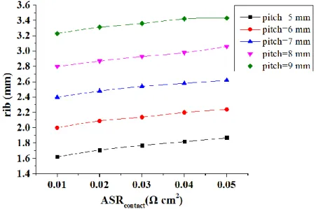
Figure 9. Dependence of the optimum anode rib size on the contact resistance and pitch width.
Figure 10. Dependence of the optimum cathode rib size on the contact resistance and pitch width.
size, which goes against the cathode-supported. What’s more, it is important to note that the cell output is significantly affected by the pitch width and reducing the pitch width is favorable to improve the property of fuel cell. However, for the manufacturing technology and engineering considerations, it is difficult to realize minimization of pitch size. In addition, there is an approximate linear relationship between the optimum rib size and the contact resistance for a fixed pitch width and thus they can still be expressed by the equation 8. The maximum error between imax and iribby using equation 9 is also less than 0.5%. In order to facilitate engineering applications, Table 5 lists the values of A and B for the optimum rib size of the anode-supported SOFC.
4. CONCLUSIONS
This paper proposes a comprehensive three-dimensional model for the property of anode- and cathode-supported SOFCs with distributed cylindrical interconnector. The model considers the contact resistances between the electrodes and ribs. The influence of anode rib size, cathode rib size and support structure on the cell performance is investigated. The analysis makes clear that optimization of rib size and pitch width as well as minimization of contact resistance are important guarantees to improve the SOFC performance. Moreover, there exists an optimum rib size to get the best output current density for a fixed contact resistance and pitch width. If the rib size chooses unreasonable, the predominance associated with the small contact resistance will be significantly reduced, or even disappear entirely. In addition, it is important to note that anode rib size and cathode rib size of anode- and cathode-supported should be optimized, respectively. The optimization results indicate that the optimal rib size is approximately linear to the contact resistance and the maximum error is within the limits permitted by project.
ACKNOWLEDGEMENTS
This work was supported by the National Science Foundation of China (21406095 and 21106058), Jiangsu province ordinary university graduate student scientific research innovation projects (YSJ14S-04) and Colleges and universities in Jiangsu high-tech ship collaborative innovation center/ Jiangsu University of Science and Technology institute of Marine equipment(1634871401-3).
References
1. Y. X. Shi, N. S. Cai, Proceedings of the Chinese Society for Electrical Engineering, 26(2006). 2. O. Razbani, M. Assadi, M. Andersson, International Journal of Hydrogen Energy, 38 (2013)
10068–10080.
3. D. F. Chen,Q. C. Zeng, S. C. Su, W. X. Bi, Z. Q. Ren, Applied Energy,112(2013) 1100–1107. 4. L. W. Chen, S. H. Gao, H. C. Zhang, International Journal of Electrochemical Science, 8 (2013)
10772 -10787.
5. J. H. Myung, H. J. Ko, J. J. Lee, S. H. Hyun, International Journal of Electrochemical Science, 6 (2011) 1617-1629.
7. P. W. Li, S. P. Chen, M. K. Chyu, Journal of Power Sources, 140 (2005) 311–318.
8. Q. Y. Chen, Q. W. Wang, J. Zhang, J. L. Yuan, International Journal of Heat and Mass Transfer, 54 (2011) 1994–2003.
9. P. W. Li, International Mechanical Engineering Congress and Exposition, 2007. 10.W. Kong, J. Y. Li, S. X. Liu, Z. J. Lin, Journal of Power Sources, 204 (2012) 106–115.
11.P. W. Li, S. P. Chen, M. K. Chyu, Journal of Fuel Cell Science and Technology, 3 (2006)188-194. 12.Q. Y. Chen, M. Zeng, J. Zhang, Q. W. Wang, International Journal of Hydrogen Energy, 35
(2010) 4292–4300.
13.Q. M. Nguyen, R. H. Craig, US Patent No. 5290642, 1994.
14.L. Andreassi, G. Rubeo, S. Ubertini, P. Lunghi, R. Bove, International Journal of Hydrogen Energy, 32 (2007) 4559 – 4574.
15.J. X. Shi, X. J. Xue, Chemical Engineering Journal, 163 (2010) 119–125. 16.W. Kong, X. Gao, S. X. Liu, S. C. Su, D. F. Chen, energies, 7 (2014) 295-313. 17.S. X. Liu, W. Kong, Z. J. Lin. Journal of Power Sources, 194 (2009) 854–863. 18.B. Todd, J. B. Young, Journal of Power Sources, 110 (2002) 186–200.
19.H. Y. Zhu, R. J. Kee, Journal of The Electrochemical Society, 155 (2008) B715–B729. 20.S. X. Liu, C. Song, Z. J. Lin, Journal of Power Sources, 183 (2008) 214–225.