doi: 10.12720/sgce.7.2.98-108
Voltage control ancillary services for low-voltage distributed
generation
Linus Idoko
, Olimpo Anaya-Lara, David Campos-Gaona
Department of Electronic & Electrical Engineering, University of Strathclyde, Glasgow, UK.Abstract
This paper sheds light on the provision of voltage control ancillary services for low-voltage distributed generation (DG) and the need for the creation of a microgrid ancillary services market since the ancillary service network operations do not include small-size energy generation. The limitations facing the participation of DG in the provision of ancillary services, the basis for the creation of microgrid ancillary services market, the gap between large power plants and small power networks, and the useful recommendations to help suggest a solution to the problem have been considered herein. This work also embraces the types of ancillary services, microgrids, DG units, voltage control ancillary services, and various types of voltage control services and their usefulness to power system networks. Various techniques for voltage control, the relationship between reactive power and voltage control, the power factor (PF) and PF corrections, and their effects on power systems have also been illustrated.
Keywords: Microgrid, voltage control, distributed generation, market
1.Introduction
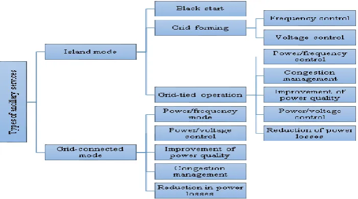
Ancillary services are the specialty services and functions provided by electric grids that facilitate and support the continuous flow of electricity to ensure that the supply will continually meet the demand. Ancillary services refer to a variety of operations beyond generation and transmission that are required to maintain grid stability and security. These services refer to those mandatory services that are required to provide support to grid operations. A number of ancillary services exist; they are supplied by different authorities and may not certainly be the same; however, some ancillary services eg black start, voltage control, and frequency control are accepted by virtually all the authorities [1]. According to previous research [2], ancillary services refer to all essential services that are usually provided by the grid and which the DSO or TSO also need so as to sustain the stability, integrity, and power quality of the distribution or transmission system.
Conversely, another research study [3] showed that customers usually demand for energy and capacity, for the power system to work effectively, in addition to these factors, a number of grid support services are essential because they equip the system operators with the resources required to sustain the immediate and continual balance between load and generation. This is to ensure that the transmission line flows are appropriately coordinated and the control schemes are implemented.
Under normal conditions and during emergencies, these ancillary services are in demand as they also make provisions for the necessary amenities required for the power system to restart when a situation wherein the balance between generation and load could not be maintained arises, resulting in a system breakdown. Figure 1 shows the types of ancillary services used in power systems.
Fig. 1. Types of ancillary services used in power systems.
1.1.Provision of ancillary services to the microgrid
A microgrid is a small-scale electricity grid that can function separately or simultaneously with the major electricity grid in its location; it usually requires different sources of energy.
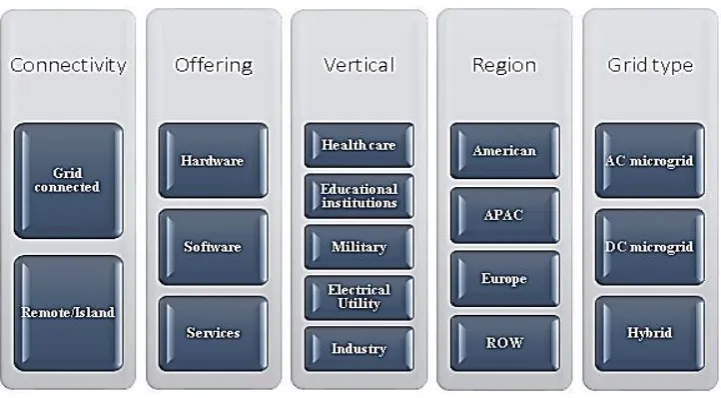
The distribution system of a microgrid is usually composed of the sources of energy, often referred to as micro-sources, a storage system alongside loads that are controllable [4]. Microgrids can be grouped into the following types, as shown in Figure 2.
Fig. 2. Types of microgrids.
[image:2.544.119.435.528.638.2]In a previous study [5], the microgrid is made up of electrical power generators, some of whose power was sourced from renewable resources, e.g., sunlight and wind, and these power generators are referred to as distributed generation (DG). Depending on the size and capacity, a microgrid as in [6] has some basic functionalities, as shown in Figure 3.
Fig. 3. Microgrid functionalities [6].
technical requirements to provide the ancillary services are satisfied by the microgrid [1]. We anticipate that in the future, the supply of electricity will depend more on DG, especially from renewable energy sources, but at the moment, the power contribution to distribution from DG, such as wind and PV, is limited and does not participate in network operations. DG units are excluded from network operations because of their unstable nature, operational cost, and size [7].
1.2.DG
[image:3.544.156.382.219.350.2]DG refers to a system or mechanism that produces electricity near the users with the use of small-scale power systems. In a previous research [8], the energy sources of the DG technology comprised non-renewable and non-renewable energy sources as well as battery storage. Using non-renewable DG, the stability of the power supply cannot be predicted since the resources are usually unstable, as reported in previous research [9]. The energy sources are shown in Figure 4.
Fig. 4. Distributed generation (DG) energy sources.
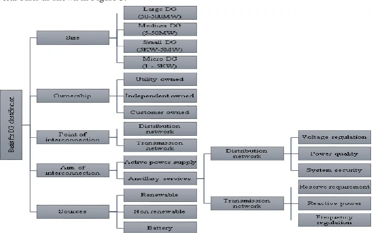
DG mainly comprises of energy sources that are modular in nature and usually comprises renewable energy sources. Because DG is usually constituted by energy from renewable sources, it has the following advantages: It is friendly to the environment, it can be made available at a much lower cost than the conventional power generators and is more reliable and secured [10]. Generally, DG classification is done on several basis as shown in Figure 5.
[image:3.544.83.459.429.665.2]DG can be operated as a utility-connected system or a standalone system and is usually installed in an isolated location, such as rural areas, where it is used to provide power supply to small buildings, large buildings, industrial sites, and estates. Generally, it is operated by individuals. DG units generate DC power or AC power, and these two forms of power cannot be connected together directly. As such, the required frequency, voltage magnitude, and phase angle are generally derived by means of power electronics interfaces.
With the aid of a suitable power electronics interface, each of the various DG units can be linked to the main grid. In some designs, a number of power electronic units are employed, whereas some designs make use of a single power electronics unit to reap some benefits, such as minimized losses, simpler design than those with a number of power electronics, and reduced cost, in terms of system control.
It has been observed that DG units comprising renewable energy sources are better than those comprising of non-renewable energy sources because, in the former type of DG units, energy sources will not be exhausted in the long run, they are environmentally friendly, and energy from the individual sources can be combined to produce a DC voltage as an input to a DC/AC inverter, which is required for grid connection or connection to a low-voltage distribution network [11].
DG has the potential to provide active power as well as ancillary services to the electrical network. In a low-voltage network, DG can operate at a power factor (PF) of unity. As such, it can be used to proffer solution to the challenges of voltage regulation, as reported in previous research [12]
This paper focuses on the application of a voltage control ancillary service to a low-voltage distribution network in a hybrid microgrid and the creation of a microgrid ancillary services market.
2.Microgrid ancillary services market
To support efficiency and encourage improvement in electrical power services, there is a need for competition among the stakeholders. The participation of distributed energy resources in power generation and the provision of ancillary services need to be supported. Currently, distributed energy resources have several limitations. Some factors responsible for the limitations, as reported in previous research [13], include the following:
The requirements and naming of the voltage control services within European countries is not homogenous as the voltage control layers are not differentiated.
The existing market structure for ancillary services supports the supply of the ancillary services via programmable generation units, i.e., non-renewable energy sources.
There is a technological limitation to the participation of renewable energy sources due to the existing regulations.
The access to participation is limited to the size of the plant because access is only restricted to plants with a capacity above 10 MVA.
2.1.The need for the creation of a microgrid ancillary services market
A market for microgrid ancillary services can create room for competition among the players, and this will result in an increase in the quality of service
Network operations are required for both low- and high-voltage distribution systems. Power quality and stability is a necessity for every electrical power network.
To create more Job and investment opportunities. To create a basis for DG and microgrid structures. To increase flexibility
2.2.The basis for the creation of a microgrid ancillary services market.
Fig. 6. The basis for the classification of the ancillary services market.
2.3.Recommendations
Some of the recommendations made to proffer solutions to the inability of distributed energy resources to participate in the provision ancillary services are shown below:
The procurement process should be enhanced and additional power sources activated.
Renewable energy sources should be allowed to participate in the provision of ancillary services whenever technically possible.
The combination of smaller energy units should be engaged and not only large-scale power units The gradient should be expressed based on the percentage of the maximum power output and not in
absolute values, e.g., 10 MW.
Harmonization of the rules for balancing and using ancillary services across countries in a geographical region, e.g., Europe, should be conducted.
For a reliable microgrid ancillary services market to function effectively, there must be an audience, usually referred to as the business target audience. The targets, in this case, are government agencies, transmission system operators, raw materials and equipment suppliers, investors, utilities, photovoltaic companies, smart grid software vendors, energy storage vendors, and microgrid system integrators and suppliers.
2.4.Market prospects for microgrid voltage control ancillary services
In the ancillary services market, volt-ampere reactive (var) utilization is the major product for voltage control. To satisfy the needs of the reactive power, the distribution system operator operates a voltage control ancillary services market so that the var needs are distributed between the numerous players whose var bids are accommodated by the distribution system. In this case, the DSO performs the role of the buyer and ensures that the market is settled. The major sources of var include the microgrids, MV-connected DG units, and HV network (if available) [7].
3.Voltage control ancillary services
achieved through the management of reactive power in an AC electrical network. In an electrical network, the transmission and distribution equipment absorbs and produces reactive power. For power systems to operate reliably and effectively, the voltage and reactive power must be controlled to meet the following objectives, as reported in the literature [14] [15]:
The movement of reactive power in an electrical system from one point to another is reduced in order to reasonably minimize the XI2 and RI2 losses.
The system stability is improved to ensure that the transmission system utilization is maximized. The voltages are within an allowable limit at the terminals of each equipment in the system.
The function of voltage control is related to the fluctuating load conditions and the corresponding reactive power compensation requirements. The voltage control ancillary services include a fault ride-through (FRT) capability, congestion management, primary voltage control, secondary voltage control, and tertiary voltage control. This can be grouped into two categories, as reported in the literature [16]: Distribution system voltage control.
Transmission system voltage control.
3.1.Distribution voltage control
Distribution voltage control, also known as volt/var, refers to voltage control at the distribution level, and its main aim is to ensure the energy losses and peak power are reduced while maintaining the voltage within the allowable limits for a number of different nominal load systems. The variables of interest include the sizes and locations of the tap changer voltage regulator and capacitor control dead bands. The voltage on the secondary side of a transformer is measured or regulated with the help of tap changers, and the tap changers are usually controlled with the help of relay controllers.
[image:6.544.169.379.367.517.2]On the contrary, transmission system voltage control can be categorized with respect to activation time, as shown in Figure 7.
Fig. 7. The categories of transmission voltage control.
3.1.1 Primary voltage control
This involves the use of automatic voltage regulators (AVRs) to ensure the voltage of the electrical devices is maintained with respect to their reference value at the point of common coupling. The values involved are normally fixed based on several factors, e.g., the maximum amount of reactive power to be supplied from any of the devices, voltage drops, and security requirements. This type of voltage control can be in operation for 1 min.
3.1.2 Secondary voltage control
3.1.3 Tertiary voltage control
This type of voltage control has the longest duration of operation (10–30 min). It operates in the entire system. Its primary purpose is to ensure that the losses are minimized, the required voltage is maintained, reactive reserves are replaced. The secondary voltage control setpoint values are provided for the operation of the network to be optimized [13].
In a distribution system, the variation in voltage across the line is given by equation (1) as follows:
(PR QX)
V
V
,
(1)
where P and Q represent the active power and reactive power generated by a power source, respectively, while the resistance and reactance of the electrical line linking the power source are represented by R and X, respectively. V represents the nominal voltage at the power source terminal [17].
With respect to equation (1), any meaningful amount of electrical power introduced by a power source, e.g., a DG unit, will result in an increase/decrease in the voltage of the power distribution system, especially if the distribution feeder is weak and its impedance is high. The variation in the voltage is also influenced by the size of the DG unit, the voltage regulation method adopted, and the location.
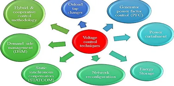
3.2.Techniques for voltage control
Some of the numerous techniques used for voltage control applied in several applications are shown in Figure 8.
Fig. 8. Techniques used for voltage control.
Over time, ancillary services have been provided by conventional generators because of the need for power generation from distributed energy resources; however, there is a need for the creation of microgrid ancillary services.
4.Reactive power and voltage control
In a power system network, when the voltage and current are not in phase, the reactive power is said to be present. It is evident that reactive power exists in a power network when (a) one waveform leads the other waveform, (b) PF of the network is less than unity, and (c) the phase angle between the current and voltage is not equal to 0°.
Reactive power is produced when the waveform of the current leads that of the voltage (often referred to as the leading PF) and consumed when the waveform of the current lags that of the voltage (usually referred to as the lagging PF) [18].
[image:7.544.129.431.306.456.2]voltage. The relationship between the real power P and the reactive power Q is given in equation (2) as follows:
. *
SPJQV I VIcos jVIsin, (2)
where S represents the apparent power, P is measured in watts, and Q is measured in var [19]. Reactive power exists as a result of a phase shift between the current and voltage curves in a power system [20]. The operation of a power system network is affected by reactive power in numerous ways, as reported in previous research [21]:
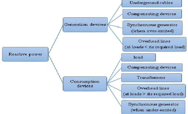
Loads absorb reactive power, which has to be supplied from some source.
Transformers and transmission lines absorb reactive power, which has to be supplied from some source, but note that every transmission line does generate a certain amount of reactive power from the charging of their shunt line, which affects their ability to consume reactive power.
The movement of reactive power from its source to sink creates extra heating in the lines and drops the voltage of the network.
The production of real power can be restricted by the production of reactive power.
4.1.Usefulness of reactive power in a power system
In an electrical power network, voltage control is very useful as it ensures that power system devices operate properly to (a) help stops problems, such as excessive heating of motors and generators, in order to minimize losses from transmission and (b) sustain the capacity of the electrical system to prevent as well as withstand voltage collapse.
Electrical power often witness under-voltage and over-voltage during operation; this challenge can be checked with the help of voltage/var control. Voltage/var control ensures that the movement of reactive power and its absorption and production at different levels in the power system are controlled. It also ensures that the voltage profile is maintained within the allowable range and that the transmission losses are minimized.
A reduction in reactive power leads to a reduction in the voltage. Conversely, increasing the reactive power increases the voltage. When a power system experiences a situation wherein the load exceeds that which the voltage can support, a voltage collapse takes place. In the event of a reduction in the supply of reactive power, the supply voltage also reduces; there has to be an increase in the current in order to maintain the power supply. This results in the absorption of more reactive power by the system, leading to a further reduction in the voltage. If the increase in current is in excess, the transmission line will go off and overload other lines in this process, thereby cascading failure results.
Conversely, if the reduction in voltage is very low, it will give rise to a situation wherein a number of generators will have to be disconnected from the network automatically to avoid being damaged.
When a power system experiences a reduction in voltage of this nature that is progressive and uncontrollable, it implies that the power system network cannot supply appropriate reactive power that is needed by the power system [16]. Other uses of reactive power, as reported in the literature [18], are as follows:
For the movement of electrons to be converted to useful work, reactive power is required by motor loads and other loads.
For active power to perform useful work, the necessary voltage level required is provided by reactive power.
It helps to regulate voltage.
For active power to move to a consumer through the distribution and transmission system, reactive power is required.
4.2.Limitations of reactive power
It cannot travel far.
A source of reactive power at a close proximity to the area of need is in better condition to deliver
reactive power than a source at a far distance from the area of need.
[image:9.544.99.409.122.310.2]The consumption and generation of reactive power are attainable with several devices, as shown in Figure 9.
Fig. 9. The absorption and generation of reactive power.
5.Power factor (PF)
For an electrical appliance, which operates using an AC supply, e.g., a fan or a refrigerator, its specification is usually given in wattage, voltage, and PF. The voltage rating of an appliance represents its nominal operating voltage, the wattage rating shows the amount of power required for the appliance when it is switched on, and PF is usually a value between 0.6 and 1. Electrical appliances usually consume power while they in operation. A large portion of the used power is converted to useful energy for its intended activity, while the remaining portion is wasted as heat. As reported in a previous study [22], PF is defined as the true power (KW) divided by the apparent power (KVA) consumed by an AC electrical appliance.
A PF value of unity is the ideal PF, but in most cases, PF is less than unity. Once it is less than 1, the implication is that more power will be required to accomplish the task. When PF is less than 1, the remaining fraction accounts for the reactive power.
PF measures the fraction of electrical power that is actually useful in performing tasks. Mathematically, there are two ways of achieving PF:
PF can be calculated using the following expression: cos
PF the cosine of the angle between real power and apparent power. PF can also be calculated as follows:
Re _ ( )
_ ( )
al power KW
PF
Apparent Power KVA
Recalling equation (2),
SPJQ, to find the magnitude of apparent power, equation (2) becomes
2 2 2
S P Q , where S P2Q2 . (3)
( )
cos
( )
P KW PF
S KVA
. (4)
that the power is ideal for transmission, but it is practically unattainable. There are multiple variations in PF because the several types of electrical devices that supply or absorb reactive power are connected to a microgrid [23].
Poor PF in a network indicates a high presence of inductive loads e.g., air-conditioning units and AC motors on the network, hence, requires a high demand for reactive power. The PF in an AC system can be unity, lagging or leading depending on the electrical devices in the network
Unity PF: This implies that the current and voltage are in phase, which means the angle between the current and voltage, in this case, is zero. As a result, the cosine of the angle or PF is unity. A load with a unity PF means that the load is purely resistive.
Lagging PF: This is the case with an inductive load in which the current vector lags the voltage vector and the PF varies with the angle of the lead. Because PF is inductive, its sign is positive.
Leading PF: A network PF is referred to as a leading PF when the current leads the voltage, and this is the case with capacitive loads in which PF varies with the angle of lead. Because PF is capacitive, its sign is negative.
5.1.PF correction
This refers to a technology that helps to bring the PF of an AC power system close to unity by providing the reactive power of opposite sign. This involves introducing capacitors and inductors that can help to neutralize the capacitive and inductive effects on the system load, respectively. For instance, a motor-load inductive effect may be canceled by connecting a capacitor locally. Similarly, the effect of a capacitive load may be offset by connecting an inductor (reactor) for PF correction [22] [23].
5.2.Usefulness of PF correction
[image:10.544.88.454.376.557.2]As reported in previous research [23], PF correction has several benefits (Figure 10).
Fig. 10. Benefits of power factor (PF) correction.
6.Conclusion
Voltage control ancillary services for low-voltage distributed DG should be allowed and the creation of a microgrid ancillary services market should be explored and implemented. The limitations concerning the participation of low voltage DG in the ancillary services were explored and useful recommendations to suggest a solution for addressing these challenges were provided. Future work will involve the design of market models for microgrid ancillary services.
It helps to cut down electricity bills
It helps to reduce carbon emissions
It reduces I2R losses in transformers and electrical devices used in distribution
It helps to reduce the heat generated in cables
It helps to reduce voltage drop
Removal of Utility penalities resulting from poor power factor
References
[1] S. Qin, “Quantification of Ancillary Service Provision by Microgrid,” McGill University Montreal, Canada, 2015. [2] M. Faiella, T. Hennig, F. Iwes, N. A. Cutululis, and F. Van Hulle, “Capabilities and costs for ancillary services provision
by wind power plants,” 2013.
[3] J. M. Bert, “Ancillary services : Technical and Commercial Insights,” Orthop. Clin. North Am., vol. 39, no. 1, p. 1–4, v, 2008.
[4] I. Luís and A. Nascimento, “Voltage and Reactive Power Control in Autonomous Microgrids,” 2017.
[5] K. . Abo-Al-Ez, X. Xia, and J. Zhang, “Smart interconnection of a PV/wind DG Micro Grid with the utility distribution network,” in 2012 Proceedings of the 9th Industrial and Commercial Use of Energy Conference, 2012, pp. 243–250. [6] A. . Fallis, “Microgrid: Architectures and Control - Front Matter,” J. Chem. Inf. Model., vol. 53, no. 9, pp. 1689–1699,
2013.
[7] A. G. Madureira and J. A. Peças Lopes, “Ancillary services market framework for voltage control in distribution networks with microgrids,” Electr. Power Syst. Res., vol. 86, no. 5, pp. 1–7, 2012.
[8] M. A. Hossain, H. R. Pota, W. Issa, and M. J. Hossain, “Overview of AC microgrid controls with inverter-interfaced generations,” Energies, vol. 10, no. 9, pp. 1–27, 2017.
[9] B. Starfield, “State of the Art in Research on Equity in Health,” J. Health Polit. Policy Law, vol. 31, no. 1, pp. 11–32, 2006.
[10] “Introduction to Distributed Generation.” [Online]. Available: http://www.dg.history.vt.edu/ch1/introduction.html. [Accessed: 24-Oct-2017].
[11] J. J. Justo, F. Mwasilu, J. Lee, and J.-W. Jung, “AC-microgrids versus DC-microgrids with distributed energy resources: A review,” Renew. Sustain. Energy Rev., vol. 24, no. April, pp. 387–405, 2013.
[12] F. Sulla, J. Björnstedt, and O. Samuelsson, “Distributed Generation with Voltage Control Capability in the Low Voltage Network,” in International Conference on Renewable Energies and Power Quality (ICREPQ’10), 2010, pp. 206–211. [13] J. Merino, G. Inés, E. Turienzo, M. Carlos, I. Cobelo, M. Andrei, S. Hanne, V. Koen, H. Enrique, Rivero Puente Seppo, K.
Pekka, E. Corentin, N. Helistö, D. Siface, and A. Zani, “Ancillary service provision by RES and DSM connected at distribution level in the future power system,” 2016.
[14] B. Kirby and E. Hirst, “Ancillary Service Details : Voltage Control,” 1997.
[15] Kundur P, Power System Stability and Control, 1st edition. McGraw-Hill: New York, NY, USA., 1994.
[16] I. O. Akwukwaegbu and O. G. Ibe, “Concepts of Reactive Power Control and Voltage Stability Methods in Power System Network,” IOSR J. Comput. Eng., vol. 11, no. 2, pp. 15–25, 2013.
[17] T. Xu and P. C. Taylor, “Voltage Control Techniques for Electrical Distribution Networks Including Distributed Generation,” in 17th IFAC World Congress - the International Federation of Automatic Control Conference, Seoul, Korea, July 6-11, 2008, pp. 11967–11971.
[18] R. Fetea and A. Petroianu, “Can the reactive power be used?,” PowerCon 2000 - 2000 Int. Conf. Power Syst. Technol. Proc., vol. 3, no. 2, pp. 1251–1255, 2000.
[19] A. Kumar and S. Vyas, “Reactive Power Control in Electrical Power Transmission System,” Int. J. Eng. Trends Technol., vol. 4, no. 5, pp. 1707–1717, 2013.
[20] a. J. Von Appen, B. C. Marnay, C. M. Stadler, D. I. Momber, E. D. Klapp, and F. A. Von Scheven, “Assessment of the economic potential of microgrids for reactive power supply,” 8th Int. Conf. Power Electron. - ECCE Asia, no. June, pp. 809–816, 2011.
[21] P. Sauer, “Reactive power and voltage control issues in electric power systems,” … Math. Restructured Electr. Power Syst., vol. Chapter 2, pp. 11–24, 2005.